

AutoCAD & AutoCAD LT All-In-One Desk Reference For Dummies (2006)
.pdf122 Let’s Get Primitive
Figure 1-2:
How many ways can you draw a circle?
The first Circle option on the Draw menu — Center, Radius — is the default method for drawing circles, and this is the method you get if you click the Circle tool on the Draw toolbar, or enter CIRCLE or its alias C at the keyboard.
If you start the command using the default option, AutoCAD prompts as follows:
Command: CIRCLE
Specify center point for circle or [3P/2P/Ttr (tan tan radius)]:
At this point, you can either locate the center point by picking a point on-screen or entering coordinates for the center point, or you can choose one of the three options inside the square brackets.
If you specify a center point, AutoCAD prompts:
Specify radius of circle or [Diameter]:
Another choice to make! You can either enter a value for the circle’s radius or pick a point on-screen to specify the radius, or you can press D to choose the diameter option. If you enter a value or pick a point, AutoCAD draws the circle and returns you to the command prompt. If you press D, AutoCAD prompts:

Let’s Get Primitive 123
Specify diameter of circle:
If this is the first circle you’ve drawn in this session, the command line is blank. If you’ve drawn a previous circle, a default value (the last-entered radius) is shown inside the angle brackets.
You can also draw circles by specifying two points that represent the endpoints of a line representing the diameter of the circle, or by specifying three points that lie on the circumference of the circle. You also can draw circles by selecting two objects your circle should be tangent to, and then entering a radius.
The Draw menu offers a sixth method that actually invokes a macro; instead of prompting you to enter a radius after you’ve selected the first two objects for tangency, AutoCAD asks you to select a third object.
Arcs of triumph
If you thought a half-dozen different ways of drawing circles was a lot, you ain’t seen nuthin’ yet! There are no fewer than 11 ways to draw arcs. Worse, the default method — 3 points — is the construction method for creating arcs that you’re least likely to encounter. Figure 1-3 shows the Arc command’s options available through the Draw menu.
Figure 1-3:
Eleven ways to draw
an arc.
Book II
Chapter 1
Objects Drawing

124 Let’s Get Primitive
While you’re getting familiar with the program, it’s easiest to use the Draw menu to choose the option you want. The nine central options on the Draw menu are all based on start points and center points, and then each has variations of end point, included angle, direction, length, or radius.
Choosing Draw Arc Start, Center, End, for example, presets the command options so that the three points you enter are indeed interpreted by AutoCAD as the start point, the center point, and the end point.
One little gotcha is that by default, AutoCAD draws arcs in a counter-clockwise direction. Figure 1-4 shows how you control the way your arcs are drawn.
Figure 1-4:
Arc direction by default is counterclockwise.
You’re probably aware that pressing Enter or the space bar, or right-clicking and choosing Enter, repeats the last command. What it doesn’t do is repeat the last command options you chose. Instead, it repeats the command with its default options. In the case of ARC, that will give you a 3-point arc, where the three points you pick are the start and end points and a random point somewhere along the arc itself. Most of the time this is not what you want.
The point of the exercise
After all that arcane arc knowledge, you’re probably ready for something simple. You’re in luck — the simplest of all AutoCAD objects is at hand. Points are geometrically defined in the drawing database by their x-, y-, z- coordinate location.

Let’s Get Primitive 125
Although we’ve been talking about x,y coordinate pairs, in fact every object in an AutoCAD drawing is located by an x-, y-, z-coordinate triplet. In most cases for 2D drafting, the value of the z coordinate is 0.
Although we’re dealing with 2D objects in this part of the book, your point object is pretty one-dimensional (kind of like some engineers we know). Since points have no length or width, they can be pretty small and hard to see. The default appearance for the point object is a single pixel, but you can change the appearance to something a little more visible by following these steps:
1.Choose Format Point Style.
AutoCAD displays the Point Style dialog box (see Figure 1-5).
2.Select one of the point styles by clicking its icon in the dialog box.
The selected style will apply to all current and future point objects in the drawing.
3.Specify the size of the point objects, and then click OK.
Set the point size as either a percentage relative to the screen size or in absolute units. If you set point size in absolute units, the point objects appear larger or smaller as you zoom in or out; if you set point size relative to screen size, point objects stay the same size.
Figure 1-5:
Style your points in the Point Style dialog box.
As we mentioned earlier, the default point style is a single pixel. Click the topleft icon in the Point Style dialog box to select it. The next icon to the right is no display at all — that’s right, you can create point objects that you can’t see. Frankly, we don’t see the point.
Book II
Chapter 1
Objects Drawing

126 Creating Construction Geometry
Creating Construction Geometry
In spite of snap, Ortho, polar, and object snaps, many AutoCAD drafters use the software the same way they drew things with pencils and t-squares — they draw temporary construction geometry to line things up and project drawing features from one view to another. AutoCAD has a couple of construction geometry tools that help with this process: construction lines and rays.
Xlines for X-men
Construction lines (commonly known as xlines) are created with the XLINE command, by default the second button down on the Draw toolbar. Xlines (and rays) are unlike any other object in AutoCAD in that they have infinite length.
Create a separate layer for your construction lines so you can easily turn them off and on when you want to see your drawing geometry without all the visual noise. Construction lines and rays will plot, so be sure to turn off the layer before you print your drawings.
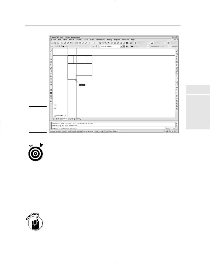
Although xlines look a lot like lines, they don’t have endpoints, so you have to construct your xlines accordingly. The following steps explain how to create a series of vertical xlines, as shown in Figure 1-6:
1.Turn on appropriate object snaps.
This is a very important step; because you’re going to be aligning your xlines with existing drawing objects, it’s important that you place them precisely.
2.Start the XLINE command using the Draw menu, Draw toolbar, or the keyboard.
AutoCAD prompts:
Command: XLINE
Specify a point or [Hor/Ver/Ang/Bisect/Offset]:
3.Type the uppercase letter of the option you want. In this case, type V and press Enter.
When you respond to the prompt, it doesn’t matter whether you type an uppercase or lowercase letter. AutoCAD prompts:
Specify through point:
4.Use the appropriate object snap mode and pick a point on the drawing geometry through which you want the xline to pass.
AutoCAD continues to create xlines until you press Enter or Esc.
Creating Construction Geometry 127
Figure 1-6:
Laying down construction lines.
If you want to lay down a whole bunch of xlines at different angles, don’t select a command option first. Your new xlines will pass through the point you pick but you’ll be able to set the angle by picking on-screen. This is an especially efficient method of laying out construction lines for a drawing if you have polar mode turned on and the correct object snaps enabled.
A little ray of sunshine
The most significant difference between a ray and a construction line is that a ray has one endpoint and extends infinitely away from that endpoint. A construction line, on the other hand, has no endpoints and therefore extends infinitely in both directions.
The following steps explain how to create rays:
1.Turn on the appropriate object snaps and enable Ortho or Polar modes as necessary.
As noted already, construction lines and rays need to be created precisely to be of any use.
Book II
Chapter 1
Objects Drawing

128 Without a Trace
2. Start the RAY command using the Draw menu or the keyboard.
By default, there is no Ray tool on the Draw toolbar. AutoCAD prompts:
Command: RAY
Specify start point:
3.Use the appropriate object snap mode and pick the point in the drawing where you want the ray to start.
AutoCAD prompts:
Specify through point:
4.Again, use an appropriate object snap mode and pick a point on the drawing geometry through which you want the ray to pass.
AutoCAD will continue creating rays from the original start point until you press Enter or Esc.
When should you use rays and when should you use xlines? Xlines are easier to construct, since they only need a through point, whereas rays need a start point and a through point. Really, the only advantage of rays is having slightly less clutter on your screen — they only disappear off one side of the screen instead of two.
For more on construction lines and rays, check out the User’s Guide in the Online Help system. Choose Help Help User’s Guide, and then navigate to Create and Modify Objects Draw Geometric Objects Draw Construction and Reference Geometry Draw Construction Lines (and Rays).
Without a Trace
Because the AutoCAD & AutoCAD LT All-in-One Desk Reference For Dummies is nothing if not comprehensive, we’re going to cover the TRACE command. As Table 1-1 shows, TRACE has no tool button or alias, and is nowhere to be found in the menu system. The TRACE command, which creates trace objects (is that pattern settling in yet?) is a prime example of AutoCAD’s attic. It’s really hard to throw anything away, even though it’s been 15 years since you last used it.
Traces had a function once. They were used in the preparation of printed circuit boards (or PCBs). Traces are more or less like lines with one significant difference: traces, like one or two other object types we’ll get to shortly, can have width. As with the LINE command, you can keep picking points and AutoCAD will continue making traces, automatically cleaning up the intersections as it goes.
Traces offer no benefits over polylines (we’ll get to polylines a bit later). Traces can’t have curved segments (polylines can). The TRACE command

A Bit Sketchy 129
lacks Close and Undo options like those in the LINE command. You can’t even see traces as you draw them.
We’re not going to tell you not to experiment with TRACE — who knows, you may find a unique use for that cast-off in AutoCAD’s attic. For a very brief description of the command, look up TRACE in the index of the online Help system. Figure 1-7 shows you some sample traces.
Figure 1-7:
Sketching with Picasso (and some traces).
A Bit Sketchy
Another antique tool from the attic is the SKETCH command. Like TRACE, you won’t find an alias or a tool button or a menu item for SKETCH. You have to type out the whole command name to run it. The SKETCH command does not create its own entity type; the end product of a SKETCH sequence is either a polyline or a whole bunch of teeny lines.
In its earliest days, AutoCAD had no commands for freehand sketching. Enter the SKETCH command. Unless you use it every day (and we can’t imagine many people do that), SKETCH takes some getting used to because it works unlike any other AutoCAD command. Follow these steps and you’ll see what we mean:
1.Type SKETCH and press Enter to start the command.
The first cryptic message appears at the command line:
Book II
Chapter 1
Objects Drawing
Command: SKETCH
Record increment <0.1000>:
130 Drawing Parallel Lines
Unlike with LINE, ARC, or CIRCLE, you don’t have to select or enter points while you’re sketching — simply moving the mouse creates the sketched entities. The prompt is telling you that any mouse movements greater than 0.1 units will be recorded. Change this value now if you want longer or shorter mouse motions to be turned into drawing entities.
2.Press Enter to continue.
AutoCAD prompts (even more cryptically, if that’s possible):
Sketch. Pen eXit Quit Record Erase Connect .
“Sketch” is an order, from AutoCAD to you!
3.Click the left mouse button to start sketching. Click again to stop sketching.
Clicking the left mouse button toggles Sketch mode between <Pen down> and <Pen up>. Simply moving the mouse a minimum of 0.l units (or whatever record increment you specified) creates sketched entities. The SKETCH command ignores object snaps, and it ignores the right mouse button.
The system variable SKPOLY determines whether SKETCH creates polyline objects or kazillions of separate lines. The default value of SKPOLY is 0 which will generate many many many lines. Setting SKPOLY to 1 tells AutoCAD to create polylines from the connected sketch segments.
Drawing Parallel Lines
If you’re drawing something like the floor plan of a house, you need parallel lines to represent the walls. The LINE command gives you a single line, which you then need to offset or copy to get a pair of lines that can represent a wall. Both AutoCAD and AutoCAD LT have commands for drawing parallel lines, but they’re different in each program.
AutoCAD LT provides a command called DLINE that enables you to draw double lines. You specify a thickness, or separation distance, and then draw. The DLINE command creates pairs of line objects that can be edited or erased separately. The DLINE command is not included in the regular version of AutoCAD 2007. For more on using DLINE, see Book IV.
Multilines (which are not included in AutoCAD LT) are multiple parallel lines that can have different properties from one another. A multiline can have up to 16 elements. You create multiline objects with the MLINE command and edit them with a special set of tools. We cover editing multilines in the next chapter.

Drawing Parallel Lines 131
Multilines definitely belong in the ranks of AutoCAD’s complex objects. To use multilines effectively, you’ll need to be able to create and edit the multipleline styles that format the multiline objects. And you’ll need to be able to edit them in the unique way that they require. It has to be said that many AutoCAD users don’t like using multilines because of their perceived inflexibility.
Making multilines
Figure 1-8 shows one example of a multiline object. Using the LINE command, it would take 24 separate lines (and a lot of editing) to get the same result.
Figure 1-8:
One multiline object makes a foundation plan.
The following steps show you how to create a simple multiline shape.
1. Choose Draw Multiline or type ML to start the MLINE command.
AutoCAD displays the MLINE options at the command prompt:
Command: MLINE
Current settings: Justification = Top, Scale = 1.00,
Style = STANDARD
Specify start point or [Justification/Scale/STyle]:
2.If you want to change justification from the current value, type J.
Justification is either Top, Zero, or Bottom, and refers to where the multiline elements are located relative to where you pick your locations. Zero justification centers the multiline elements on the points you pick. If Justification is Top, and you draw your multilines from left to right, the points you pick will be at the top element of the multiline. If you draw a closed shape with multilines, drawing clockwise with Top justification
Book II
Chapter 1
Objects Drawing