

46 RF CMOS POWER AMPLIFIERS:THEORY,DESIGN AND IMPLEMENTATION
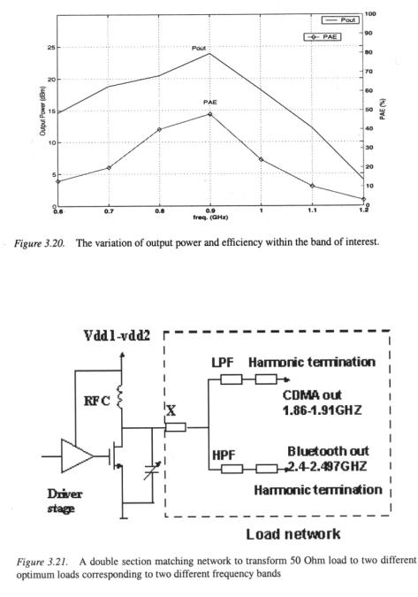
discussion, it is evident that the same amplifier core can be utilized at different band, without sacrificing performance provided that the level of output power is preserved.
7.Summary
This chapter has presented the design and implementation of a 900MHz class- E PA. The single-ended input, single-ended output amplifier has been imple- mented in  CMOS technology. Measurement results have shown a maximum output power of 24dBm delivered to a 50Ohm load with 48% efficiency, operating from a 2V supply. Different layout considerations, and the effect of ground inductance has been discussed. A physically-based model of the class-E PA has been used to question the advantages and disadvantage of using the same amplifier core for multi-mode operation. A 1.9GHz power am- plifier that uses the same core of the fabricated 900 MHz amplifier has been presented. Thus proving that the same amplifier core can be utilized at a different frequency band, without sacrificing performance, provided that the level of output power is preserved.

A 900MHz Class E CMOS PA |
47 |

48 RF CMOS POWER AMPLIFIERS:THEORY,DESIGN AND IMPLEMENTATION

A 900MHz Class E CMOS PA |
49 |

50 RF CMOS POWER AMPLIFIERS:THEORY,DESIGN AND IMPLEMENTATION
A 900MHz Class E CMOS PA |
51 |

52 RF CMOS POWER AMPLIFIERS:THEORY,DESIGN AND IMPLEMENTATION
A 900MHz Class E CMOS PA |
53 |

54 RF CMOS POWER AMPLIFIERS:THEORY,DESIGN AND IMPLEMENTATION