

6.Experiments
.pdfChapter 5
DISCRETE SEMICONDUCTOR CIRCUITS
5.1Introduction
A semiconductor device is one made of silicon or any number of other specially prepared materials designed to exploit the unique properties of electrons in a crystal lattice, where electrons are not as free to move as in a conductor, but are far more mobile than in an insulator. A discrete device is one contained in its own package, not built on a common semiconductor substrate with other components, as is the case with ICs, or integrated circuits. Thus, "discrete semiconductor circuits" are circuits built out of individual semiconductor components, connected together on some kind of circuit board or terminal strip. These circuits employ all the components and concepts explored in the previous chapters, so a ¯rm comprehension of DC and AC electricity is essential before embarking on these experiments.
Just for fun, one circuit is included in this section using a vacuum tube for ampli¯cation instead of a semiconductor transistor. Before the advent of transistors, "vacuum tubes" were the workhorses of the electronics industry: used to make recti¯ers, ampli¯ers, oscillators, and many other circuits. Though now considered obsolete for most purposes, there are still some applications for vacuum tubes, and it can be fun building and operating circuits using these devices.
193

194 |
CHAPTER 5. DISCRETE SEMICONDUCTOR CIRCUITS |
5.2Commutating diode
PARTS AND MATERIALS
²6 volt battery
²Power transformer, 120VAC step-down to 12VAC (Radio Shack catalog # 273-1365, 273-1352, or 273-1511).
²One 1N4001 rectifying diode (Radio Shack catalog # 276-1101)
²One neon lamp (Radio Shack catalog # 272-1102)
²Two toggle switches, SPST ("Single-Pole, Single-Throw")
A power transformer is speci¯ed, but any iron-core inductor will su±ce, even the home-made inductor or transformer from the AC experiments chapter!
The diode need not be an exact model 1N4001. Any of the "1N400X" series of rectifying diodes are suitable for the task, and they are quite easy to obtain.
I recommend household light switches for their low cost and durability.
CROSS-REFERENCES
Lessons In Electric Circuits, Volume 1, chapter 16: "RC and L/R Time Constants" Lessons In Electric Circuits, Volume 3, chapter 3: "Diodes and Recti¯ers"
LEARNING OBJECTIVES
²Review inductive "kickback"
²Learn how to suppress "kickback" using a diode
SCHEMATIC DIAGRAM |
|
|
|
|
Switch |
|
|
|
#1 |
Switch |
|
|
|
|
|
|
|
#2 |
|
Battery |
Inductor |
|
Neon |
|
|
Diode |
lamp |
|
|
|
|
ILLUSTRATION |
|
|
|
5.2. COMMUTATING DIODE |
195 |
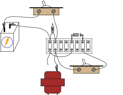
Switch #1
-
+
120 V 
Switch #2
12 V
INSTRUCTIONS
When assembling the circuit, be very careful of the diode's orientation. The cathode end of the diode (the end marked with a single band) must face the positive (+) side of the battery. The diode should be reverse-biased and nonconducting with switch #1 in the "on" position. Use the high-voltage (120 V) winding of the transformer for the inductor coil. The primary winding of a step-down transformer has more inductance than the secondary winding, and will give a greater lamp-°ashing e®ect.
Set switch #2 to the "o®" position. This disconnects the diode from the circuit so that it has no e®ect. Quickly close and open (turn "on" and then "o®") switch #1. When that switch is opened, the neon bulb will °ash from the e®ect of inductive "kickback." Rapid current decrease caused by the switch's opening causes the inductor to create a large voltage drop as it attempts to keep current at the same magnitude and going in the same direction.
Inductive kickback is detrimental to switch contacts, as it causes excessive arcing whenever they are opened. In this circuit, the neon lamp actually diminishes the e®ect by providing an alternate current path for the inductor's current when the switch opens, dissipating the inductor's stored energy harmlessly in the form of light and heat. However, there is still a fairly high voltage dropped across the opening contacts of switch #1, causing undue arcing and shortened switch life.
If switch #2 is closed (turned "on"), the diode will now be a part of the circuit. Quickly close and open switch #1 again, noting the di®erence in circuit behavior. This time, the neon lamp does not °ash. Connect a voltmeter across the inductor to verify that the inductor is still receiving full battery voltage with switch #1 closed. If the voltmeter registers only a small voltage with switch #1 "on," the diode is probably connected backward, creating a short-circuit.

196 |
CHAPTER 5. DISCRETE SEMICONDUCTOR CIRCUITS |
5.3Half-wave recti¯er
PARTS AND MATERIALS
²Low-voltage AC power supply (6 volt output)
²6 volt battery
²One 1N4001 rectifying diode (Radio Shack catalog # 276-1101)
²Small "hobby" motor, permanent-magnet type (Radio Shack catalog # 273-223 or equivalent)
²Audio detector with headphones
²0.1 ¹F capacitor (Radio Shack catalog # 272-135 or equivalent)
The diode need not be an exact model 1N4001. Any of the "1N400X" series of rectifying diodes are suitable for the task, and they are quite easy to obtain.
See the AC experiments chapter for detailed instructions on building the "audio detector" listed here. If you haven't built one already, you're missing a simple and valuable tool for experimentation.
A 0.1 ¹F capacitor is speci¯ed for "coupling" the audio detector to the circuit, so that only AC reaches the detector circuit. This capacitor's value is not critical. I've used capacitors ranging from 0.27 ¹F to 0.015 ¹F with success. Lower capacitor values attenuate low-frequency signals to a greater degree, resulting in less sound intensity from the headphones, so use a greater-value capacitor value if you experience di±culty hearing the tone(s).
CROSS-REFERENCES
Lessons In Electric Circuits, Volume 3, chapter 3: "Diodes and Recti¯ers"
LEARNING OBJECTIVES
²Function of a diode as a recti¯er
²Permanent-magnet motor operation on AC versus DC power
²Measuring "ripple" voltage with a voltmeter
SCHEMATIC DIAGRAM
Diode
AC
power Mtr (motor) supply
ILLUSTRATION

5.3. HALF-WAVE RECTIFIER |
197 |
Low-voltage
AC power supply
12
 6
6 
 6
6 
Diode
Motor 
INSTRUCTIONS
Connect the motor to the low-voltage AC power supply through the rectifying diode as shown. The diode only allows current to pass through during one half-cycle of a full positive-and-negative cycle of power supply voltage, eliminating one half-cycle from ever reaching the motor. As a result, the motor only "sees" current in one direction, albeit a pulsating current, allowing it to spin in one direction.
Take a jumper wire and short past the diode momentarily, noting the e®ect on the motor's operation:

198 |
CHAPTER 5. DISCRETE SEMICONDUCTOR CIRCUITS |
Low-voltage
AC power supply
|
12 |
Temporary |
6 |
6 |
jumper |
As you can see, permanent-magnet "DC" motors do not function well on alternating current. Remove the temporary jumper wire and reverse the diode's orientation in the circuit. Note the e®ect on the motor.
Measure DC voltage across the motor like this:

5.3. HALF-WAVE RECTIFIER |
199 |
|
|
|
|
|
|
|
|
|
|
|
|
V |
A |
Low-voltage |
V |
A |
|
|
OFF |
||
AC power supply |
|
|
|
|
|
A |
COM |
|
12 |
|
|
6 |
6 |
|
|
Then, measure AC voltage across the motor as well:
|
|
V |
A |
Low-voltage |
V |
A |
|
|
OFF |
||
AC power supply |
|
|
|
|
|
A |
COM |
|
12 |
|
|
6 |
6 |
|
|

200 |
CHAPTER 5. DISCRETE SEMICONDUCTOR CIRCUITS |
Most digital multimeters do a good job of discriminating AC from DC voltage, and these two measurements show the DC average and AC "ripple" voltages, respectively of the power "seen" by the motor. Ripple voltage is the varying portion of the voltage, interpreted as an AC quantity by measurement equipment although the voltage waveform never actually reverses polarity. Ripple may be envisioned as an AC signal superimposed on a steady DC "bias" or "o®set" signal. Compare these measurements of DC and AC with voltage measurements taken across the motor while powered by a battery:
 V
V  A
A
V A
OFF
A COM
-
+
Batteries give very "pure" DC power, and as a result there should be very little AC voltage measured across the motor in this circuit. Whatever AC voltage is measured across the motor is due to the motor's pulsating current draw as the brushes make and break contact with the rotating commutator bars. This pulsating current causes pulsating voltages to be dropped across any stray resistances in the circuit, resulting in pulsating voltage "dips" at the motor terminals.
A qualitative assessment of ripple voltage may be obtained by using the sensitive audio detector described in the AC experiments chapter (the same device described as a "sensitive voltage detector" in the DC experiments chapter). Turn the detector's sensitivity down for low volume, and connect it across the motor terminals through a small (0.1 ¹F) capacitor, like this:

5.3. HALF-WAVE RECTIFIER |
201 |
headphones
Capacitor
0.1 μF
Sensitivity
plug
-
+
The capacitor acts as a high-pass ¯lter, blocking DC voltage from reaching the detector and allowing easier "listening" of the remaining AC voltage. This is the exact same technique used in oscilloscope circuitry for "AC coupling," where DC signals are blocked from viewing by a seriesconnected capacitor. With a battery powering the motor, the ripple should sound like a highpitched "buzz" or "whine." Try replacing the battery with the AC power supply and rectifying diode, "listening" with the detector to the low-pitched "buzz" of the half-wave recti¯ed power:

202 |
CHAPTER 5. DISCRETE SEMICONDUCTOR CIRCUITS |
Low-voltage AC power supply
12
 6
6 
 6
6 
headphones
Sensitivity |
plug |
|
COMPUTER SIMULATION
Schematic with SPICE node numbers:
|
D1 |
1 |
2 |
V1 |
Rload |
0 |
0 |
Netlist (make a text ¯le containing the following text, verbatim):
Halfwave rectifier
v1 1 0 sin(0 8.485 60 0 0) rload 2 0 10k
d1 1 2 mod1
.model mod1 d
.tran .5m 25m
.plot tran v(1,0) v(2,0)
.end
This simulation plots the input voltage as a sine wave and the output voltage as a series of "humps" corresponding to the positive half-cycles of the AC source voltage. The dynamics of a DC motor are far too complex to be simulated using SPICE, unfortunately.