

6.Experiments
.pdf3.11. MAKE YOUR OWN MULTIMETER |
113 |
² Soldering practice
SCHEMATIC DIAGRAM
|
Movement |
|
|
|
- |
+ |
|
|
|
|
Off |
|
|
|
A |
Rshunt |
|
Rmultiplier1 |
mA |
|
Rmultiplier2 |
V |
|
|
|
||
|
|
Rmultiplier3 |
V |
|
|
|
V |
"Common" |
A |
V/mA |
|
jack |
|
|
|
"Rmultiplier" resistors are actually rheostat networks
Rmultiplier
ILLUSTRATION

114 |
CHAPTER 3. DC CIRCUITS |
|
Meter |
|
movement |
Common |
+ |
- |
|
Rshunt |
|
A |
|
V/mA |
|
Selector |
|
switch |
|
INSTRUCTIONS
First, you need to determine the characteristics of your meter movement. Most important is to know the full scale de°ection in milliamps or microamps. To determine this, connect the meter movement, a potentiometer, battery, and digital ammeter in series. Adjust the potentiometer until the meter movement is de°ected exactly to full-scale. Read the ammeter's display to ¯nd the fullscale current value:

3.11. MAKE YOUR OWN MULTIMETER |
115 |
|
Meter |
|
movement |
- |
+ |
Potentiometer
-
+


 V
V 


 A
A


 V
V 


 A
A
OFF
A COM
Be very careful not to apply too much current to the meter movement, as movements are very sensitive devices and easily damaged by overcurrent. Most meter movements have full-scale de°ection current ratings of 1 mA or less, so choose a potentiometer value high enough to limit current appropriately, and begin testing with the potentiometer turned to maximum resistance. The lower the full-scale current rating of a movement, the more sensitive it is.
After determining the full-scale current rating of your meter movement, you must accurately measure its internal resistance. To do this, disconnect all components from the previous testing circuit and connect your digital ohmmeter across the meter movement terminals. Record this resistance ¯gure along with the full-scale current ¯gure obtained in the last procedure.
Perhaps the most challenging portion of this project is determining the proper range resistance values and implementing those values in the form of rheostat networks. The calculations are outlined in chapter 8 of volume 1 ("Metering Circuits"), but an example is given here. Suppose your meter movement had a full-scale rating of 1 mA and an internal resistance of 400 -. If we wanted to determine the necessary range resistance ("Rmultiplier ") to give this movement a range of 0 to 15 volts, we would have to divide 15 volts (total applied voltage) by 1 mA (full-scale current) to obtain the total probe-to-probe resistance of the voltmeter (R=E/I). For this example, that total resistance is 15 k-. From this total resistance ¯gure, we subtract the movement's internal resistance, leaving 14.6 k- for the range resistor value. A simple rheostat network to produce 14.6 k- (adjustable) would be a 10 k- potentiometer in parallel with a 10 k- ¯xed resistor, all in series with another 10 k- ¯xed resistor:
116 |
CHAPTER 3. DC CIRCUITS |
≈ 15 kΩ, adjustable
10 kΩ |
10 kΩ |
|
10 kΩ |
One position of the selector switch directly connects the meter movement between the black Common binding post and the red V/mA binding post. In this position, the meter is a sensitive ammeter with a range equal to the full-scale current rating of the meter movement. The far clockwise position of the switch disconnects the positive (+) terminal of the movement from either red binding post and shorts it directly to the negative (-) terminal. This protects the meter from electrical damage by isolating it from the red test probe, and it "dampens" the needle mechanism to further guard against mechanical shock.
The shunt resistor (Rshunt) necessary for a high-current ammeter function needs to be a lowresistance unit with a high power dissipation. You will de¯nitely not be using any 1/4 watt resistors for this, unless you form a resistance network with several smaller resistors in parallel combination. If you plan on having an ammeter range in excess of 1 amp, I recommend using a thick piece of wire or even a skinny piece of sheet metal as the "resistor," suitably ¯led or notched to provide just the right amount of resistance.
To calibrate a home-made shunt resistor, you will need to connect the your multimeter assembly to a calibrated source of high current, or a high-current source in series with a digital ammeter for reference. Use a small metal ¯le to shave o® shunt wire thickness or to notch the sheet metal strip in small, careful amounts. The resistance of your shunt will increase with every stroke of the ¯le, causing the meter movement to de°ect more strongly. Remember that you can always approach the exact value in slower and slower steps (¯le strokes), but you cannot go "backward" and decrease the shunt resistance!
Build the multimeter circuit on a breadboard ¯rst while determining proper range resistance values, and perform all calibration adjustments there. For ¯nal construction, solder the components on to a printed-circuit board. Radio Shack sells printed circuit boards that have the same layout as a breadboard, for convenience (catalog # 276-170). Feel free to alter the component layout from what is shown.
I strongly recommend that you mount the circuit board and all components in a sturdy box, so that the meter is durably ¯nished. Despite the limitations of this multimeter (no resistance function, inability to measure alternating current, and lower precision than most purchased analog multimeters), it is an excellent project to assist learning fundamental instrument principles and circuit function. A far more accurate and versatile multimeter may be constructed using many of the same parts if an ampli¯er circuit is added to it, so save the parts and pieces for a later experiment!
3.12. SENSITIVE VOLTAGE DETECTOR |
117 |
3.12Sensitive voltage detector
PARTS AND MATERIALS
²High-quality "closed-cup" audio headphones
²Headphone jack: female receptacle for headphone plug (Radio Shack catalog # 274-312)
²Small step-down power transformer (Radio Shack catalog # 273-1365 or equivalent, using the 6-volt secondary winding tap)
²Two 1N4001 rectifying diodes (Radio Shack catalog # 276-1101)
²1 k- resistor
²100 k- potentiometer (Radio Shack catalog # 271-092)
²Two "banana" jack style binding posts, or other terminal hardware, for connection to potentiometer circuit (Radio Shack catalog # 274-662 or equivalent)
²Plastic or metal mounting box
Regarding the headphones, the higher the "sensitivity" rating in decibels (dB), the better, but listening is believing: if you're serious about building a detector with maximum sensitivity for small electrical signals, you should try a few di®erent headphone models at a high-quality audio store and "listen" for which ones produce an audible sound for the lowest volume setting on a radio or CD player. Beware, as you could spend hundreds of dollars on a pair of headphones to get the absolute best sensitivity! Take heart, though: I've used an old pair of Radio Shack "Realistic" brand headphones with perfectly adequate results, so you don't need to buy the best.
A transformer is a device normally used with alternating current ("AC") circuits, used to convert high-voltage AC power into low-voltage AC power, and for many other purposes. It is not important that you understand its intended function in this experiment, other than it makes the headphones become more sensitive to low-current electrical signals.
Normally, the transformer used in this type of application (audio speaker impedance matching) is called an "audio transformer," with its primary and secondary windings represented by impedance values (1000 - : 8 -) instead of voltages. An audio transformer will work, but I've found small step-down power transformers of 120/6 volt ratio to be perfectly adequate for the task, cheaper (especially when taken from an old thrift-store alarm clock radio), and far more rugged.
The tolerance (precision) rating for the 1 k- resistor is irrelevant. The 100 k- potentiometer is a recommended option for incorporation into this project, as it gives the user control over the loudness for any given signal. Even though an audio-taper potentiometer would be appropriate for this application, it is not necessary. A linear-taper potentiometer works quite well.
CROSS-REFERENCES
Lessons In Electric Circuits, Volume 1, chapter 8: "DC Metering Circuits"
Lessons In Electric Circuits, Volume 1, chapter 10: "DC Network Analysis" (in regard to the Maximum Power Transfer Theorem)
Lessons In Electric Circuits, Volume 2, chapter 9: "Transformers"
Lessons In Electric Circuits, Volume 2, chapter 12: "AC Metering Circuits"
118 |
CHAPTER 3. DC CIRCUITS |
LEARNING OBJECTIVES
²Soldering practice
²Detection of extremely small electrical signals
²Using a potentiometer as a voltage divider/signal attenuator
²Using diodes to "clip" voltage at some maximum level
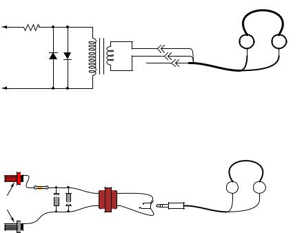
SCHEMATIC DIAGRAM
headphones
test lead |
transformer |
|
|
1 kΩ |
jack plug |
diodes |
|
test lead
ILLUSTRATION
headphones
|
resistor |
6 V |
|
120 V |
|
Binding |
diodes |
|
posts |
|
|
|
|
transformer jack plug
INSTRUCTIONS
The headphones, most likely being stereo units (separate left and right speakers) will have a three-contact plug. You will be connecting to only two of those three contact points. If you only have a "mono" headphone set with a two-contact plug, just connect to those two contact points. You may either connect the two stereo speakers in series or in parallel. I've found the series connection to work best, that is, to produce the most sound from a small signal:

3.12. SENSITIVE VOLTAGE DETECTOR |
119 |
To transformer |
To transformer |
common right left |
common right left |
Speakers in series |
Speakers in parallel |
Solder all wire connections well. This detector system is extremely sensitive, and any loose wire connections in the circuit will add unwanted noise to the sounds produced by the measured voltage signal. The two diodes (arrow-like component symbols) connected in parallel with the transformer's primary winding, along with the series-connected 1 k- resistor, work together to prevent any more than about 0.7 volts from being dropped across the primary coil of the transformer. This does one thing and one thing only: limit the amount of sound the headphones can produce. The system will work without the diodes and resistor in place, but there will be no limit to sound volume in the circuit, and the resulting sound caused by accidently connecting the test leads across a substantial voltage source (like a battery) can be deafening!
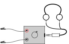
Binding posts provide points of connection for a pair of test probes with banana-style plugs, once the detector components are mounted inside a box. You may use ordinary multimeter probes, or make your own probes with alligator clips at the ends for secure connection to a circuit.
Detectors are intended to be used for balancing bridge measurement circuits, potentiometric (null-balance) voltmeter circuits, and detect extremely low-amplitude AC ("alternating current") signals in the audio frequency range. It is a valuable piece of test equipment, especially for the low-budget experimenter without an oscilloscope. It is also valuable in that it allows you to use a di®erent bodily sense in interpreting the behavior of a circuit.
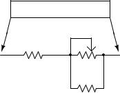
For connection across any non-trivial source of voltage (1 volt and greater), the detector's extremely high sensitivity should be attenuated. This may be accomplished by connecting a voltage divider to the "front" of the circuit:
SCHEMATIC DIAGRAM
test lead
1 kΩ
100
kΩ
test lead
ILLUSTRATION
120 |
|
|
|
|
|
|
|
|
|
|
|
|
|
|
|
|
|
|
|
|
|
CHAPTER 3. DC CIRCUITS |
||
|
|
|
|
|
|
|
|
|
|
|
|
|
|
|
|
|
|
|
|
|
|
|
|
|
|
|
|
|
|
|
|
|
|
|
|
|
|
|
|
|
|
|
|
|
|
|
|
|
|
|
|
|
|
|
|
|
|
|
|
|
|
|
|
|
|
|
|
|
|
|
|
|
|
|
|
|
|
|
|
|
|
|
|
|
|
|
|
|
|
|
|
|
|
|
|
|
|
|
|
|
|
|
|
|
|
|
|
|
|
|
|
|
|
|
|
|
|
|
|
|
|
|
|
|
|
|
|
|
|
|
|
|
|
|
|
|
|
|
|
|
|
|
|
|
|
|
|
|
|
|
|
|
|
|
|
|
|
|
|
|
|
|
|
|
|
|
|
|
|
|
|
|
|
|
|
|
|
|
|
|
|
|
|
|
|
|
|
|
|
|
|
|
|
|
|
|
|
|
|
potentiometer
Adjust the 100 k- voltage divider potentiometer to about mid-range when initially sensing a voltage signal of unknown magnitude. If the sound is too loud, turn the potentiometer down and try again. If too soft, turn it up and try again. The detector produces a "click" sound whenever the test leads make or break contact with the voltage source under test. With my cheap headphones, I've been able to detect currents of less than 1/10 of a microamp (< 0.1 ¹A).
A good demonstration of the detector's sensitivity is to touch both test leads to the end of your tongue, with the sensitivity adjustment set to maximum. The voltage produced by metal- to-electrolyte contact (called galvanic voltage) is very small, but enough to produce soft "clicking" sounds every time the leads make and break contact on the wet skin of your tongue.
Try unplugged the headphone plug from the jack (receptacle) and similarly touching it to the end of your tongue. You should still hear soft clicking sounds, but they will be much smaller in amplitude. Headphone speakers are "low impedance" devices: they require low voltage and "high" current to deliver substantial sound power. Impedance is a measure of opposition to any and all forms of electric current, including alternating current (AC). Resistance, by comparison, is a strictly measure of opposition to direct current (DC). Like resistance, impedance is measured in the unit of the Ohm (-), but it is symbolized in equations by the capital letter "Z" rather than the capital letter "R". We use the term "impedance" to describe the headphone's opposition to current because it is primarily AC signals that headphones are normally subjected to, not DC.
Most small signal sources have high internal impedances, some much higher than the nominal 8 - of the headphone speakers. This is a technical way of saying that they are incapable of supplying substantial amounts of current. As the Maximum Power Transfer Theorem predicts, maximum sound power will be delivered by the headphone speakers when their impedance is "matched" to the impedance of the voltage source. The transformer does this. The transformer also helps aid the detection of small DC signals by producing inductive "kickback" every time the test lead circuit is broken, thus "amplifying" the signal by magnetically storing up electrical energy and suddenly releasing it to the headphone speakers.
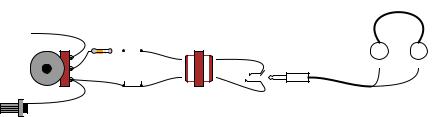
I recommend building this detector in a permanent fashion (mounting all components inside of a box, and providing nice test lead wires) so it may be easily used in the future. Constructed as such, it might look something like this:
3.12. SENSITIVE VOLTAGE DETECTOR |
121 |
headphones
Test leads
Sensitivity |
plug |
|

122 |
CHAPTER 3. DC CIRCUITS |
3.13Potentiometric voltmeter
PARTS AND MATERIALS
²Two 6 volt batteries
²One potentiometer, single turn, 10 k-, linear taper (Radio Shack catalog # 271-1715)
²Two high-value resistors (at least 1 M- each)
²Sensitive voltage detector (from previous experiment)
²Analog voltmeter (from previous experiment)
The potentiometer value is not critical: anything from 1 k- to 100 k- is acceptable. If you have built the "precision potentiometer" described earlier in this chapter, it is recommended that you use it in this experiment.
Likewise, the actual values of the resistors are not critical. In this particular experiment, the greater the value, the better the results. They need not be precisely equal value, either.
If you have not yet built the sensitive voltage detector, it is recommended that you build one before proceeding with this experiment! It is a very useful, yet simple, piece of test equipment that you should not be without. You can use a digital multimeter set to the "DC millivolt" (DC mV) range in lieu of a voltage detector, but the headphone-based voltage detector is more appropriate because it demonstrates how you can make precise voltage measurements without using expensive or advanced meter equipment. I recommend using your home-made multimeter for the same reason, although any voltmeter will su±ce for this experiment.
CROSS-REFERENCES
Lessons In Electric Circuits, Volume 1, chapter 8: "DC Metering Circuits"
LEARNING OBJECTIVES
²Voltmeter loading: its causes and its solution
²Using a potentiometer as a source of variable voltage
²Potentiometric method of voltage measurement
SCHEMATIC DIAGRAM
1 MΩ 
6 V
|
|
|
measure voltage |
|
|
1 MΩ |
between these |
|
|
two test points |
|
|
|
|
|
null |
6 V |
Test |
+ |
probes |
V |
|
- |
Potentiometric voltmeter