

Finkenzeller K.RFID handbook.2003
.pdf2.5 SELECTION CRITERIA FOR RFID SYSTEMS |
25 |
from a few bytes to over 100 Kbyte EEPROM (passive transponder) or SRAM (active, i.e. transponder with battery backup). These transponders are able to process simple reader commands for the selective reading and writing of the data memory in a permanently encoded state machine. In general, the transponders also support anticollision procedures, so that several transponders located in the reader’s interrogation zone at the same time do not interfere with one another and can be selectively addressed by the reader (see Section 7.2).
Cryptological procedures, i.e. authentication between transponder and reader, and data stream encryption (see Chapter 8) are also common in these systems. These systems are operated at all frequencies available to RFID systems.
2.4.3High-end systems
The high-end segment is made up of systems with a microprocessor and a smart card operating system (smart card OS). The use of microprocessors facilitates the realisation of significantly more complex encryption and authentication algorithms than would be possible using the hard-wired logic of a state machine. The top end of high-end systems is occupied by modern dual interface smart cards (see Section 10.2.1), which have a cryptographic coprocessor. The enormous reduction in computing times that results from the use of a coprocessor means that contactless smart cards can even be used in applications that impose high requirements on the secure encryption of the data transmission, such as electronic purse or ticketing systems for public transport.
High-end systems are almost exclusively operated at the 13.56 MHz frequency. Data transmission between transponder and reader is described in the standard ISO 14443.
2.5 Selection Criteria for RFID Systems
There has been an enormous upsurge in the popularity of RFID systems in recent years. The best example of this phenomenon is the contactless smart cards used as electronic tickets for public transport. Five years ago it was inconceivable that tens of millions of contactless tickets would now be in use. The possible fields of application for contactless identification systems have also multiplied recently.
Developers of RFID systems have taken this development into account, with the result that countless systems are now available on the market. The technical parameters of these systems are optimised for various fields of application — ticketing, animal identification, industrial automation or access control. The technical requirements of these fields of application often overlap, which means that the clear classification of suitable systems is no simple matter. To make matters more difficult, apart from a few special cases (animal identification, close coupling smart cards), no binding standards are as yet in place for RFID systems.
It is difficult even for a specialist to retain an overview of the range of RFID systems currently on offer. Therefore, it is not always easy for users to select the system best suited to their needs.
In what follows there are some points for consideration when selecting RFID systems.
26 |
2 DIFFERENTIATION FEATURES OF RFID SYSTEMS |
2.5.1Operating frequency
RFID systems that use frequencies between approximately 100 kHz and 30 MHz operate using inductive coupling. By contrast, microwave systems in the frequency range 2.45–5.8 GHz are coupled using electromagnetic fields.
The specific absorption rate (damping) for water or non-conductive substances is lower by a factor of 100 000 at 100 kHz than it is at 1 GHz. Therefore, virtually no absorption or damping takes place. Lower frequency HF systems are primarily used due to the better penetration of objects (Schurmann,¨ 1994). An example of this is the bolus, a transponder placed in the omasum (rumen) of cattle, which can be read from outside at an interrogation frequency of <135 kHz.
Microwave systems have a significantly higher range than inductive systems, typically 2–15 m. However, in contrast to inductive systems, microwave systems require an additional backup battery. The transmission power of the reader is generally insufficient to supply enough power for the operation of the transponder.
Another important factor is sensitivity to electromagnetic interference fields, such as those generated by welding robots or strong electric motors. Inductive transponders are at a significant disadvantage here. Microwave systems have therefore particularly established themselves in the production lines and painting systems of the automotive industry. Other factors are the high memory capacity (up to 32 Kbyte) and the high temperature resistance of microwave systems (Bachthaler, 1997).
2.5.2Range
The required range of an application is dependent upon several factors (Figure 2.18):
•the positional accuracy of the transponder;
•the minimum distance between several transponders in practical operation;
•the speed of the transponder in the interrogation zone of the reader.
For example, in contactless payment applications — e.g. public transport tickets — the positioning speed is very low, since the transponder is guided to the reader by hand. The minimum distance between several transponders in this case corresponds with the distance between two passengers entering a vehicle. For such systems there is an optimal range of 5–10 cm. A greater range would only give rise to problems in this case, since several passengers’ tickets might be detected by the reader simultaneously. This would make it impossible to reliably allocate the ticket to the correct passenger.
Different vehicle models of varying dimensions are often constructed simultaneously on the production lines of the automotive industry. Thus great variations in the distance between the transponder on the vehicle and the reader are pre-programmed (Bachthaler, 1997). The write/read distance of the RFID system used must therefore be designed for the maximum required range. The distance between the transponders must be such that only one transponder is ever within the interrogation zone of the reader at a time. In this situation, microwave systems in which the field has a directional beam offer clear advantages over the broad, nondirectional fields of inductively coupled systems.
2.5 SELECTION CRITERIA FOR RFID SYSTEMS |
27 |
Inductive coupling
Electromagnetic coupling (backscatter) nondirectional
1 |
2 |
3 m |
Electromagnetic coupling (backscatter) directional
Figure 2.18 Comparison of the relative interrogation zones of different systems
The speed of transponders, relative to readers, together with the maximum write/read distance, determines the length of time spent in the reader’s interrogation zone. For the identification of vehicles, the required range of the RFID system is designed such that at the maximum vehicle speed the length of time spent in the interrogation zone is sufficient for the transmission of the required data.
2.5.3 Security requirements
Security requirements to be imposed on a planned RFID application, i.e. encryption and authentication, should be assessed very precisely to rule out any nasty surprises in the implementation phase. For this purpose, the incentive that the system represents to a potential attacker as a means of procuring money or material goods by manipulation should be evaluated. In order to be able to assess this attraction, we divide applications into two groups:
•industrial or closed applications;
•public applications connected with money and material goods.
This can be illustrated on the basis of two contrasting application examples.
Let us once again consider an assembly line in the automotive industry as a typical example of an industrial or closed application. Only authorised persons have access to this RFID system, so the circle of potential attackers remains reasonably small. A malicious attack on the system by the alteration or falsification of the data on a transponder could bring about a critical malfunction in the operating sequence, but the attacker would not gain any personal benefit. The probability of an attack can thus be
28 |
2 DIFFERENTIATION FEATURES OF RFID SYSTEMS |
set equal to zero, meaning that even a cheap low-end system without security logic can be used.
Our second example is a ticketing system for use in public transport. Such a system, primarily data carriers in the form of contactless smart cards, is accessible to anyone. The circle of potential attackers is thus enormous. A successful attack on such a system could represent large-scale financial damage to the public transport company in question, for example in the event of the organised sale of falsified travel passes, to say nothing of the damage to the company’s image. For such applications a highend transponder with authentication and encryption procedures is indispensable. For applications with maximum security requirements, for example banking applications with an electronic purse, only transponders with microprocessors should be used.
2.5.4 Memory capacity
The chip size of the data carrier — and thus the price class — is primarily determined by its memory capacity. Therefore, permanently encoded read-only data carriers are used in price-sensitive mass applications with a low local information requirement. However, only the identity of an object can be defined using such a data carrier. Further data is stored in the central database of the controlling computer. If data is to be written back to the transponder, a transponder with EEPROM or RAM memory technology is required.
EEPROM memories are primarily found in inductively coupled systems. Memory capacities of 16 bytes to 8 Kbytes are available.
SRAM memory devices with a battery backup, on the other hand, are predominantly used in microwave systems. The memory capacities on offer range from 256 bytes to 64 Kbytes.
RFID Handbook: Fundamentals and Applications in Contactless Smart Cards and Identification, Second Edition
Klaus Finkenzeller Copyright 2003 John Wiley & Sons, Ltd.
ISBN: 0-470-84402-7
3
Fundamental Operating
Principles
This chapter describes the basic interaction between transponder and reader, in particular the power supply to the transponder and the data transfer between transponder and reader (Figure 3.1). For a more in-depth description of the physical interactions and mathematical models relating to inductive coupling or backscatter systems please refer to Chapter 4.
3.11-Bit Transponder
A bit is the smallest unit of information that can be represented and has only two states: 1 and 0. This means that only two states can be represented by systems based upon a 1-bit transponder: ‘transponder in interrogation zone’ and ‘no transponder in interrogation zone’. Despite this limitation, 1-bit transponders are very widespread — their main field of application is in electronic anti-theft devices in shops (EAS, electronic article surveillance).
An EAS system is made up of the following components: the antenna of a ‘reader’ or interrogator, the security element or tag, and an optional deactivation device for deactivating the tag after payment. In modern systems deactivation takes place when the price code is registered at the till. Some systems also incorporate an activator, which is used to reactivate the security element after deactivation (Gillert, 1997). The main performance characteristic for all systems is the recognition or detection rate in relation to the gate width (maximum distance between transponder and interrogator antenna).
The procedure for the inspection and testing of installed article surveillance systems is specified in the guideline VDI 4470 entitled ‘Anti-theft systems for goods — detection gates. Inspection guidelines for customers’. This guideline contains definitions and testing procedures for the calculation of the detection rate and false alarm ratio. It can be used by the retail trade as the basis for sales contracts or for monitoring the performance of installed systems on an ongoing basis. For the product manufacturer, the Inspection Guidelines for Customers represents an effective benchmark in the development and optimisation of integrated solutions for security projects (in accordance with VDI 4470).

30 |
3 FUNDAMENTAL OPERATING PRINCIPLES |
1 bit (EAS)
3.1
RFID systems
n bit (memory) electronic/ physical
Full and half duplex
3.2
Sequential
3.3
Radio frequency 3.1.1
Microwaves
3.1.2
Frequency divider 3.1.3
Electromagnetic
3.1.4
Acoustomagnetic
3.1.5
Inductive coupling 3.2.1
Electromagnetic backscatter 3.2.2
Close coupling 3.2.3
Electrical coupling 3.2.4
Inductive coupling 3.3.1
SAW 3.3.2
Figure 3.1 The allocation of the different operating principles of RFID systems into the sections of the chapter
3.1.1Radio frequency
The radio frequency (RF) procedure is based upon LC resonant circuits adjusted to a defined resonant frequency fR. Early versions employed inductive resistors made of wound enamelled copper wire with a soldered on capacitor in a plastic housing (hard tag). Modern systems employ coils etched between foils in the form of stick-on labels. To ensure that the damping resistance does not become too high and reduce the quality of the resonant circuit to an unacceptable level, the thickness of
3.1 1-BIT TRANSPONDER |
31 |
the aluminium conduction tracks on the 25 µm thick polyethylene foil must be at least 50 µm (Jorn,¨ 1994). Intermediate foils of 10 µm thickness are used to manufacture the capacitor plates.
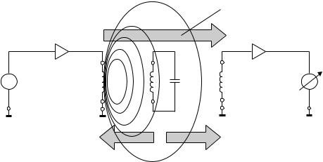
The reader (detector) generates a magnetic alternating field in the radio frequency range (Figure 3.2). If the LC resonant circuit is moved into the vicinity of the magnetic alternating field, energy from the alternating field can be induced in the resonant circuit via its coils (Faraday’s law). If the frequency fG of the alternating field corresponds with the resonant frequency fR of the LC resonant circuit the resonant circuit produces a sympathetic oscillation. The current that flows in the resonant circuit as a result of this acts against its cause, i.e. it acts against the external magnetic alternating field (see Section 4.1.10.1). This effect is noticeable as a result of a small change in the voltage drop across the transmitter’s generator coil and ultimately leads to a weakening of the measurable magnetic field strength. A change to the induced voltage can also be detected in an optional sensor coil as soon as a resonant oscillating circuit is brought into the magnetic field of the generator coil.
The relative magnitude of this dip is dependent upon the gap between the two coils (generator coil — security element, security element — sensor coil) and the quality Q of the induced resonant circuit (in the security element).
The relative magnitude of the changes in voltage at the generator and sensor coils is generally very low and thus difficult to detect. However, the signal should be as clear as possible so that the security element can be reliably detected. This is achieved using a bit of a trick: the frequency of the magnetic field generated is not constant, it is ‘swept’. This means that the generator frequency continuously crosses the range between minimum and maximum. The frequency range available to the swept systems is 8.2 MHz ±10% (Jorn,¨ 1994).
Whenever the swept generator frequency exactly corresponds with the resonant frequency of the resonant circuit (in the transponder), the transponder begins to oscillate, producing a clear dip in the voltages at the generator and sensor coils (Figure 3.3). Frequency tolerances of the security element, which depend upon manufacturing tolerances
Magnetic alternating field
Energy
fG |
Generator coil |
|
Sensor coil |
UHF |
|
Transmitter |
EAS label |
Receiver |
|
|
|
|
||
|
Feedback |
Feedback |
(optional) |
|
|
|
|
Figure 3.2 Operating principle of the EAS radio frequency procedure
32 |
3 FUNDAMENTAL OPERATING PRINCIPLES |
Impedance of generator coil (Ohm)
300
250
200
150
100
50
0
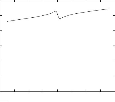
7.2 × 10⁶ 7.4 × 10⁶ 7.6 × 10⁶ 7.8 × 10⁶ 8 × 10⁶ 8.2 × 10⁶ 8.4 × 10⁶ 8.6 × 10⁶ 8.8 × 10⁶
Frequency (MHz)
|Z1|
Figure 3.3 The occurrence of an impedance ‘dip’ at the generator coil at the resonant frequency of the security element (Q = 90, k = 1%). The generator frequency fG is continuously swept between two cut-off frequencies. An RF tag in the generator field generates a clear dip at its resonant frequency fR
and vary in the presence of a metallic environment, no longer play a role as a result of the ‘scanning’ of the entire frequency range.
Because the tags are not removed at the till, they must be altered so that they do not activate the anti-theft system. To achieve this, the cashier places the protected product into a device — the deactivator — that generates a sufficiently high magnetic field that the induced voltage destroys the foil capacitor of the transponder. The capacitors are designed with intentional short-circuit points, so-called dimples. The breakdown of the capacitors is irreversible and detunes the resonant circuit to such a degree that this can no longer be excited by the sweep signal.
Large area frame antennas are used to generate the required magnetic alternating field in the detection area. The frame antennas are integrated into columns and combined to form gates. The classic design that can be seen in every large department store is illustrated in Figure 3.4. Gate widths of up to 2 m can be achieved using the RF procedure. The relatively low detection rate of 70% (Gillert, 1997) is disproportionately influenced by certain product materials. Metals in particular (e.g. food tins) affect the resonant frequency of the tags and the coupling to the detector coil and thus have a negative effect on the detection rate. Tags of 50 mm × 50 mm must be used to achieve the gate width and detection rate mentioned above.

3.1 1-BIT TRANSPONDER |
33 |
|
|
|
|
Coil |
Tags: |
|
Stick on tag (Back of barcode)
 Column
 PVC hard tag
Figure 3.4 Left, typical frame antenna of an RF system (height 1.20–1.60 m); right, tag designs
Table 3.1 Typical system parameters for RF systems (VDI 4471)
|
Quality factor Q of the security element |
>60–80 |
|
|
||
|
Minimum deactivation field strength HD |
1.5 A/m |
|
|
||
|
Maximum field strength in the deactivation range |
0.9 A/m |
|
|
||
|
|
|
||||
Table 3.2 Frequency range of different RF security systems (Plotzke et al., 1994) |
||||||
|
|
|
|
|
|
|
|
|
System 1 |
System 2 |
System 3 |
System 4 |
|
|
|
|
|
|
||
Frequency (MHz) |
1.86–2.18 |
7.44–8.73 |
7.30–8.70 |
7.40–8.60 |
||
Sweep frequency (Hz) |
141 |
141 |
85 |
85 |
||
|
|
|
|
|
|
|
The range of products that have their own resonant frequencies (e.g. cable drums) presents a great challenge for system manufacturers. If these resonant frequencies lie within the sweep frequency 8.2 MHz ± 10% they will always trigger false alarms.
3.1.2Microwaves
EAS systems in the microwave range exploit the generation of harmonics at components with nonlinear characteristic lines (e.g. diodes). The harmonic of a sinusoidal voltage A with a defined frequency fA is a sinusoidal voltage B, whose frequency fB is an integer multiple of the frequency fA. The subharmonics of the frequency fA are thus the frequencies 2fA, 3fA, 4fA etc. The N th multiple of the output frequency is termed the N th harmonic (N th harmonic wave) in radio-engineering; the output frequency itself is termed the carrier wave or first harmonic.
In principle, every two-terminal network with a nonlinear characteristic generates harmonics at the first harmonic. In the case of nonlinear resistances, however, energy is consumed, so that only a small part of the first harmonic power is converted into the harmonic oscillation. Under favourable conditions, the multiplication of f to n × f

34 |
3 FUNDAMENTAL OPERATING PRINCIPLES |
occurs with an efficiency of η = 1/n2. However, if nonlinear energy storage is used for multiplication, then in the ideal case there are no losses (Fleckner, 1987).
Capacitance diodes are particularly suitable nonlinear energy stores for frequency multiplication. The number and intensity of the harmonics that are generated depend upon the capacitance diode’s dopant profile and characteristic line gradient. The exponent n (also γ ) is a measure for the gradient (=capacitance-voltage characteristic). For simple diffused diodes, this is 0.33 (e.g. BA110), for alloyed diodes it is 0.5 and for tuner diodes with a hyper-abrupt P-N junction it is around 0.75 (e.g. BB 141) (Intermetal Semiconductors ITT, 1996).
The capacitance-voltage characteristic of alloyed capacitance diodes has a quadratic path and is therefore best suited for the doubling of frequencies. Simple diffused diodes can be used to produce higher harmonics (Fleckner, 1987).
The layout of a 1-bit transponder for the generation of harmonics is extremely simple: a capacitance diode is connected to the base of a dipole adjusted to the carrier wave (Figure 3.5). Given a carrier wave frequency of 2.45 GHz the dipole has a total length of 6 cm. The carrier wave frequencies used are 915 MHz (outside Europe), 2.45 GHz or 5.6 GHz. If the transponder is located within the transmitter’s range, then the flow of current within the diode generates and re-emits harmonics of the carrier wave. Particularly distinctive signals are obtained at two or three times the carrier wave, depending upon the type of diode used.
Transponders of this type cast in plastic (hard tags) are used mainly to protect textiles. The tags are removed at the till when the goods are paid for and they are subsequently reused.
Figure 3.6 shows a transponder being placed within the range of a microwave transmitter operating at 2.45 GHz. The second harmonic of 4.90 GHz generated in the diode characteristic of the transponder is re-transmitted and detected by a receiver, which is adjusted to this precise frequency. The reception of a signal at the frequency of the second harmonic can then trigger an alarm system.
If the amplitude or frequency of the carrier wave is modulated (ASK, FSK), then all harmonics incorporate the same modulation. This can be used to distinguish between ‘interference’ and ‘useful’ signals, preventing false alarms caused by external signals.
Dipole
fA
Capacitance diode
Housing
fA
2 × fA
Basic circuit |
Mechanical design |
Figure 3.5 Basic circuit and typical construction format of a microwave tag