

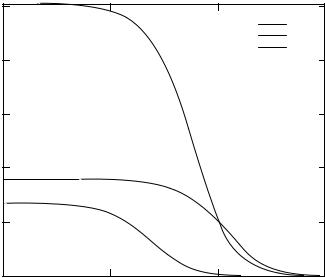
Finkenzeller K.RFID handbook.2003
.pdf66 |
4 PHYSICAL PRINCIPLES OF RFID SYSTEMS |
Magnetic field strength H (A/m)
4
3
2
1
0
0
x = 10 cm x = 20 cm x = 30 cm
1.5 A/m (ISO 14443)
0.2 |
0.4 |
0.6 |
0.8 |
1 |
Radius R (m)
Figure 4.5 Field strength H of a transmission antenna given a constant distance x and variable radius R, where I = 1 A and N = 1
The optimal radius of a transmission antenna is thus twice the maximum desired read range. The second zero point is negative merely because the magnetic field H of a conductor loop propagates in both directions of the x axis (see also Figure 4.3).
However, an accurate assessment of a system’s maximum read range requires knowledge of the interrogation field strength Hmin of the transponder in question (see Section 4.1.9). If the selected antenna radius is too great, then there is the danger that the field strength H may be too low to supply the transponder with sufficient operating energy, even at a distance x = 0.
4.1.2Magnetic flux and magnetic flux density
The magnetic field of a (cylindrical) coil will exert a force on a magnetic needle. If a soft iron core is inserted into a (cylindrical) coil — all other things remaining equal — then the force acting on the magnetic needle will increase. The quotient I × N (Section 4.1.1) remains constant and therefore so does field strength. However, the flux density — the total number of flux lines — which is decisive for the force generated (cf. Pauls, 1993), has increased.
The total number of lines of magnetic flux that pass through the inside of a cylindrical coil, for example, is denoted by magnetic flux . Magnetic flux density B is a further variable related to area A (this variable is often referred to as ‘magnetic inductance B in the literature’) (Reichel, 1980). Magnetic flux is expressed as:
= B · A |
(4.8) |

4.1 MAGNETIC FIELD |
67 |
Magnetic flux Φ
Area A
B line 
Figure 4.6 Relationship between magnetic flux and flux density B
The material relationship between flux density B and field strength H (Figure 4.6) is expressed by the material equation:
B = µ0µrH = µH |
(4.9) |
The constant µ0 is the magnetic field constant (µ0 = 4π × 10−6 Vs/Am) and describes the permeability (= magnetic conductivity) of a vacuum. The variable µr is called relative permeability and indicates how much greater than or less than µ0 the permeability of a material is.
4.1.3Inductance L
A magnetic field, and thus a magnetic flux , will be generated around a conductor of any shape. This will be particularly intense if the conductor is in the form of a loop (coil). Normally, there is not one conduction loop, but N loops of the same area A, through which the same current I flows. Each of the conduction loops contributes the same proportion to the total flux ψ (Paul, 1993).
|
|
= N = N · = N · µ · H · A |
(4.10) |
N
The ratio of the interlinked flux ψ that arises in an area enclosed by current I , to the current in the conductor that encloses it (conductor loop) is denoted by inductance L (Figure 4.7):
L |
= |
|
= |
N · |
= |
N · µ · H · A |
|
(4.11) |
|
I |
I |
I |
|||||||
|
|
||||||||
Φ(I), Ψ(I)
A
I
Enclosing current
Figure 4.7 Definition of inductance L
68 |
4 PHYSICAL PRINCIPLES OF RFID SYSTEMS |
Inductance is one of the characteristic variables of conductor loops (coils). The inductance of a conductor loop (coil) depends totally upon the material properties (permeability) of the space that the flux flows through and the geometry of the layout.
4.1.3.1Inductance of a conductor loop
If we assume that the diameter d of the wire used is very small compared to the diameter D of the conductor coil (d/D < 0.0001) a very simple approximation can be used:
L = N2µ0R · ln |
2d |
(4.12) |
|
|
|
R |
|
where R is the radius of the conductor loop and d is the diameter of the wire used.
4.1.4 Mutual inductance M
If a second conductor loop 2 (area A2) is located in the vicinity of conductor loop 1 (area A1), through which a current is flowing, then this will be subject to a proportion of the total magnetic flux flowing through A1. The two circuits are connected together by this partial flux or coupling flux. The magnitude of the coupling flux ψ21 depends upon the geometric dimensions of both conductor loops, the position of the conductor loops in relation to one another, and the magnetic properties of the medium (e.g. permeability) in the layout.
Similarly to the definition of the (self) inductance L of a conductor loop, the mutual inductance M21 of conductor loop 2 in relation to conductor loop 1 is defined as the ratio of the partial flux ψ21 enclosed by conductor loop 2, to the current I1 in conductor loop 1 (Paul, 1993):
M21 = |
I1 |
= A2 |
2I1 1 |
|
· d A2 |
(4.13) |
|
21(I1) |
|
B (I |
) |
|
|
Similarly, there is also a mutual inductance M12. Here, current I2 flows through the conductor loop 2, thereby determining the coupling flux ψ12 in loop 1. The following relationship applies:
M = M12 = M21 |
(4.14) |
Mutual inductance describes the coupling of two circuits via the medium of a magnetic field (Figure 4.8). Mutual inductance is always present between two electric circuits. Its dimension and unit are the same as for inductance.
The coupling of two electric circuits via the magnetic field is the physical principle upon which inductively coupled RFID systems are based. Figure 4.9 shows a calculation of the mutual inductance between a transponder antenna and three different reader antennas, which differ only in diameter. The calculation is based upon the following values: M1: R = 55 cm, M2: R = 7.5 cm, M3: R = 1 cm, transponder: R = 3.5 cm. N = 1 for all reader antennas.
The graph of mutual inductance shows a strong similarity to the graph of magnetic field strength H along the x axis. Assuming a homogeneous magnetic field, the mutual

4.1 MAGNETIC FIELD |
69 |
Φ(I1), Ψ(I1)
 B2(I1)
I1
A1 |
A2 |
Total flux |
Ψ2(I1) |
Figure 4.8 The definition of mutual inductance M21 by the coupling of two coils via a partial magnetic flow
|
1× 10⁻⁷ |
|
|
|
|
|
|||
|
1× 10⁻⁸ |
|
|
|
M (Henry) |
1× 10⁻⁹ |
|
|
|
1× 10⁻¹⁰ |
|
|
||
inductance |
1 |
× 10−11 |
|
|
|
|
|
||
Mutual |
1 |
× 10−12 |
|
|
|
|
|
||
|
|
|
||
|
1× 10⁻¹³ |
|
|
|
|
|
|
||
|
|
|
||
|
|
|
||
|
|
|
||
|
|
|
||
|
|
|
||
|
|
|
||
|
|
|
||
|
1× 10⁻¹⁴ |
|
|
|
|
|
|||
|
|
1× 10⁻³ |
||
M1
M2
M3
0.01 |
0.1 |
1 |
Distance x (m)
Figure 4.9 Graph of mutual inductance between reader and transponder antenna as the distance in the x direction increases
inductance M12 between two coils can be calculated using equation (4.13). It is found to be:
M |
12 |
= |
B2(I1) · N2 |
· A2 |
= |
µ0 · H (I1) · N2 · A2 |
(4.15) |
I1 |
|
I1 |
|||||
|
|
|
We first replace H (I1) with the expression in equation (4.4), and substitute R2π for
A, thus obtaining: |
|
|
µ0 · N1 · R12 · N2 · R22 · π |
|
|||
M |
12 |
= |
(4.16) |
||||
2 |
|
|
|||||
|
(R12 + x2)3 |
|
|
||||

70 4 PHYSICAL PRINCIPLES OF RFID SYSTEMS
In order to guarantee the homogeneity of the magnetic field in the area A2 the condition A2 ≤ A1 should be fulfilled. Furthermore, this equation only applies to the case where the x axes of the two coils lie on the same plane. Due to the relationship
M = M12 = M21 |
the mutual inductance can be calculated as follows for the case |
||||||
A2 ≥ A1: |
M |
21 |
= |
µ0 · N1 · R12 · N2 · R22 · π |
(4.17) |
||
|
|
|
|
||||
|
|
|
|
|
|||
2(R22 + x2)3
4.1.5Coupling coefficient k
Mutual inductance is a quantitative description of the flux coupling of two conductor loops. The coupling coefficient k is introduced so that we can make a qualitative prediction about the coupling of the conductor loops independent of their geometric dimensions. The following applies:
k = |
√ |
M |
(4.18) |
|
|
L1 · L2 |
|
The coupling coefficient always varies between the two extreme cases 0 ≤ k ≤ 1.
•k = 0: Full decoupling due to great distance or magnetic shielding.
•k = 1: Total coupling. Both coils are subject to the same magnetic flux . The transformer is a technical application of total coupling, whereby two or more coils are wound onto a highly permeable iron core.
An analytic calculation is only possible for very simple antenna configurations. For two parallel conductor loops centred on a single x axis the coupling coefficient according to Roz and Fuentes (n.d.) can be approximated from the following equation. However, this only applies if the radii of the conductor loops fulfil the condition rTransp ≤ rReader. The distance between the conductor loops on the x axis is denoted by x.
k(x) ≈ |
|
rTransp2 |
· rReader2 |
|
|
(4.19) |
|||
√rTransp · rReader · |
|
|
|
|
3 |
||||
|
x2 |
+ rReader2 |
|
|
|
||||
|
|
|
|
|
|
|
|
|
|
Due to the fixed link between the coupling coefficient and mutual inductance M, and because of the relationship M = M12 = M21, the formula is also applicable to transmitter antennas that are smaller than the transponder antenna. Where rTransp ≥
rReader, we write: |
|
rTransp2 |
· rReader2 |
|
|
||
k(x) ≈ |
|
|
(4.20) |
||||
√ |
|
|
3 |
||||
|
· |
x2 + rTransp2 |
|||||
rTransp · rReader |
|
||||||
The coupling coefficient k(x) = 1 (= 100%) is achieved where the distance between the conductor loops is zero (x = 0) and the antenna radii are identical (rTransp = rReader),
4.1 MAGNETIC FIELD |
71 |
Coupling coefficient k (x)
Coupling coefficient k = f(x)
0.25
r1 r2 r3
0.2
0.15
0.1
0.05
1× 10⁻³ |
0.01 |
0.1 |
1 |
|
|
Distance x (m) |
|
Figure 4.10 Graph of the coupling coefficient for different sized conductor loops. Transponder antenna: rTransp = 2 cm, reader antenna: r1 = 10 cm, r2 = 7.5 cm, r3 = 1 cm
because in this case the conductor loops are in the same place and are exposed to exactly the same magnetic flux ψ.
In practice, however, inductively coupled transponder systems operate with coupling coefficients that may be as low as 0.01 (<1%) (Figure 4.10).
4.1.6 Faraday’s law
Any change to the magnetic flux generates an electric field strength Ei. This characteristic of the magnetic field is described by Faraday’s law.
The effect of the electric field generated in this manner depends upon the material properties of the surrounding area. Figure 4.11 shows some of the possible effects (Paul, 1993):
•Vacuum: in this case, the field strength E gives rise to an electric rotational field. Periodic changes in magnetic flux (high frequency current in an antenna coil) generate an electromagnetic field that propagates itself into the distance.
•Open conductor loop: an open circuit voltage builds up across the ends of an almost closed conductor loop, which is normally called induced voltage. This voltage corresponds with the line integral (path integral) of the field strength E that is
generated along the path of the conductor loop in space.

72 |
4 PHYSICAL PRINCIPLES OF RFID SYSTEMS |
Flux change dΦ/dt
Conductor (e.g. metal surface)
Eddy current,
Current density S
Open conductor loop
Ui
Nonconductor (vacuum), Induced field strength Ei => Electromagnetic wave
Figure 4.11 Induced electric field strength E in different materials. From top to bottom: metal surface, conductor loop and vacuum
•Metal surface: an electric field strength E is also induced in the metal surface. This causes free charge carriers to flow in the direction of the electric field strength. Currents flowing in circles are created, so-called eddy currents. This works against the exciting magnetic flux (Lenz’s law), which may significantly damp the magnetic flux in the vicinity of metal surfaces. However, this effect is undesirable in inductively coupled RFID systems (installation of a transponder or reader antenna on a metal surface) and must therefore be prevented by suitable countermeasures (see Section 4.1.12.3).
In its general form Faraday’s law is written as follows:
ui = Ei · ds = − d (t) (4.21) dt
For a conductor loop configuration with N windings, we can also say that ui = N · d /dt. (The value of the contour integral ∫ Ei · ds can be increased N times if the closed integration path is carried out N times; Paul, 1993).
To improve our understanding of inductively coupled RFID systems we will now consider the effect of inductance on magnetically coupled conduction loops.
A time variant current i1 (t) in conduction loop L1 generates a time variant magnetic flux d (i1)/dt. In accordance with the inductance law, a voltage is induced in the conductor loops L1 and L2 through which some degree of magnetic flux is flowing. We can differentiate between two cases:
•Self-inductance: the flux change generated by the current change din/dt induces a voltage un in the same conductor circuit.
•Mutual inductance: the flux change generated by the current change din/dt induces a voltage in the adjacent conductor circuit Lm. Both circuits are coupled by mutual inductance.
Figure 4.12 shows the equivalent circuit diagram for coupled conductor loops. In an inductively coupled RFID system L1 would be the transmitter antenna of the reader.

4.1 MAGNETIC FIELD |
|
|
|
|
73 |
|
B2(i1) |
|
|
|
|
|
i1 |
M |
i2 |
R2 |
|
|
u2 |
|
|
|
|
M |
L2 |
L1 |
L2 |
u2 |
RL |
u1
L1
Figure 4.12 Left, magnetically coupled conductor loops; right, equivalent circuit diagram for magnetically coupled conductor loops
L2 represents the antenna of the transponder, where R2 is the coil resistance of the transponder antenna. The current consumption of the data memory is symbolised by the load resistor RL.
A time varying flux in the conductor loop L1 induces voltage u2i in the conductor loop L2 due to mutual inductance M. The flow of current creates an additional voltage drop across the coil resistance R2, meaning that the voltage u2 can be measured at the terminals. The current through the load resistor RL is calculated from the expression u2/RL. The current through L2 also generates an additional magnetic flux, which opposes the magnetic flux 1(i1). The above is summed up in the following equation:
u2 = + |
d 2 |
= M |
di1 |
− L2 |
di2 |
− i2R2 |
(4.22) |
dt |
dt |
dt |
Because, in practice, i1 and i2 are sinusoidal (HF) alternating currents, we write
equation (4.22) in the more appropriate complex notation (where ω = 2πf): |
|
u2 = j ωM · i1 − j ωL2 · i2 − i2R2 |
(4.23) |
If i2 is replaced by u2/RL in equation (4.23), then we can solve the equation for u2:
u2 |
= |
|
jwM · i1 |
RL → ∞: u2 = jωM · i1 |
|
1 + |
|
jwL2 + R2 |
(4.24) |
||
|
|
|
|||
|
|
|
RL |
RL → 0: u2 → 0 |
|
|
|
|
|
||
4.1.7Resonance
The voltage u2 induced in the transponder coil is used to provide the power supply to the data memory (microchip) of a passive transponder (see Section 4.1.8.1). In order to significantly improve the efficiency of the equivalent circuit illustrated in Figure 4.12, an additional capacitor C2 is connected in parallel with the transponder coil L2 to form a parallel resonant circuit with a resonant frequency that corresponds with the

74 |
4 PHYSICAL PRINCIPLES OF RFID SYSTEMS |
operating frequency of the RFID system in question.1 The resonant frequency of the parallel resonant circuit can be calculated using the Thomson equation:
f = |
2π |
√ |
1 |
(4.25) |
|
|
L2 · C2 |
|
In practice, C2 is made up of a parallel capacitor C2 and a parasitic capacitance Cp from the real circuit. C2 = (C2 + Cp). The required capacitance for the parallel capacitor C2 is found using the Thomson equation, taking into account the parasitic capacitance Cp:
C2 |
= |
1 |
− Cp |
(4.26) |
(2πf )2L2 |
Figure 4.13 shows the equivalent circuit diagram of a real transponder. R2 is the natural resistance of the transponder coil L2 and the current consumption of the data carrier (chip) is represented by the load resistor RL.
If a voltage uQ2 = ui is induced in the coil L2, the following voltage u2 can be measured at the data carrier load resistor RL in the equivalent circuit diagram shown in Figure 4.13:
|
|
u2 |
|
|
|
|
|
|
|
uQ2 |
|
|
|
|
|
|
|
|
(4.27) |
||
|
|
= 1 + (j ωL2 + R2) · RL + j ωC2 |
|||||||||||||||||||
|
|
|
|
|
|
|
|
|
|
|
|
|
|
1 |
|
|
|
|
|
|
|
We now replace the induced voltage |
uQ2 = ui |
by the factor responsible for its |
|||||||||||||||||||
generation, uQ2 = ui = j ωM · i1 = ω · k · |
√ |
|
|
|
· i1, thus obtaining the relationship |
||||||||||||||||
L1 · L2 |
|||||||||||||||||||||
|
|
M |
|
|
|
R |
2 |
|
|
C |
2 |
= C |
p |
+ C ′ |
|
|
|
|
|
||
|
|
|
|
|
|
|
|
|
|
2 |
|
|
|
|
|
||||||
i1 |
|
L2 |
i2 |
|
|
|
|
|
u2 |
|
|
|
|
|
|
|
|
|
|||
|
|
|
|
|
|
|
|
|
|
|
|
|
|
|
|||||||
|
|
L1 |
|
|
|
|
|
|
|
|
|
|
|
|
|
|
|
|
|
||
|
|
|
|
|
|
|
|
|
|
|
|
|
|
|
|
|
|
|
|||
|
|
|
|
|
Cp |
|
|
|
|
|
|
C ′ |
|
|
|
|
|
||||
|
|
|
|
|
|
|
|
|
|
|
|
|
|
|
|
||||||
|
|
|
|
|
|
|
|
|
|
|
|
|
|
|
RL |
|
|
||||
|
|
|
|
uQ2 |
|
|
|
|
|
|
|
2 |
|
|
|
||||||
|
|
|
|
|
|
|
|
|
|
|
|
|
|
|
|
|
|
||||
|
|
|
|
|
|
|
|
|
|
|
|
|
|
|
|
|
|
||||
|
|
|
|
|
|
|
|
|
|
|
|
Parallel C (‘tuning C’) |
|
||||||||
|
|
|
|
|
|
|
|
|
|
|
|
|
|
|
|||||||
|
|
|
|
|
|
|
|
|
|
|
|
|
|
|
|
Parasitic capacitor |
|
||||
|
|
|
|
|
|
|
|
|
|
|
|
|
|
|
|
|
|||||
|
|
|
|
|
|
|
|
|
|
|
|
|
|
|
|
|
|||||
Figure 4.13 Equivalent circuit diagram for magnetically coupled conductor loops. Transponder coil L2 and parallel capacitor C2 form a parallel resonant circuit to improve the efficiency of voltage transfer. The transponder’s data carrier is represented by the grey box
1 However, in 13.56 MHz systems with anticollision procedures, the resonant frequency selected for the transponder is often 1–5 MHz higher to minimise the effect of the interaction between transponders on overall performance. This is because the overall resonant frequency of two transponders directly adjacent to one another is always lower than the resonant frequency of a single transponder.

4.1 MAGNETIC FIELD |
75 |
between voltage u2 and the magnetic coupling of transmitter coil and transponder coil:
u2 |
= |
|
j ωM · i1 |
(4.28) |
||||
1 + (j ωL2 |
|
|
|
|
||||
|
+ R2) · |
RL + j ωC2 |
|
|||||
|
|
|
|
|
1 |
|
|
|
and: |
|
j ω · k · √ |
|
|
|
· i1 |
|
|
u2 |
= |
L1 · L2 |
(4.29) |
|||||
|
|
|
||||||
|
1 + (j ωL2 |
+ R2) · |
RL + j ωC2 |
|
||||
|
|
|
|
|
1 |
|
|
|
or in the non-complex form (Jurisch, 1994):
|
|
|
|
|
ω · k · √ |
|
· i1 |
|
|
|
|
|
||
u |
2 = |
|
|
|
L1L2 |
|
|
|
|
(4.30) |
||||
|
|
|
|
|
|
|
|
|
|
|||||
|
|
RL2 |
+ ωR2C2 |
2 |
+ 1 − ω2L2C2 |
+ RL |
|
2 |
|
|||||
|
|
|
|
|
|
|
|
|
|
|
|
|
|
|
where C2 = C2 + Cp.
Figure 4.14 shows the simulated graph of u2 with and without resonance over a large frequency range for a possible transponder system. The current i1 in the transmitter antenna (and thus also (i1)), inductance L2, mutual inductance M, R2 and RL are held constant over the entire frequency range.
We see that the graph of voltage u2 for the circuit with the coil alone (circuit from Figure 4.12) is almost identical to that of the parallel resonant circuit (circuit from
100
10
|u2| (V)
1
0.1
1 × 10⁶ |
1 × 10⁷ |
1 × 10⁸ |
|
||
|
|
|
f (Hz) |
|
|
|
|
u2 Resonant |
|
|
|
|
|
|
|
|
|
|
|
u2 Coil |
|
|
|
Figure 4.14 Plot of voltage at a transponder coil in the frequency |
range 1 to |
100 MHz, |
|||
given a constant magnetic field strength H |
or constant current i1. A |
transponder |
coil with |
||
a parallel capacitor shows a clear voltage |
step-up when excited at |
its resonant |
frequency |
||
(fRES = 13.56 MHz) |
|
|
|
||