

336 Radio Engineering for Wireless Communication and Sensor Applications
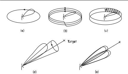
Figure 12.20 Scanning techniques: (a) circular scanning; (b) stepped circular scanning;
(c) nodding circular scanning; (d) conical scanning; and (e) monopulse.
from all four beams. Therefore, the fluctuation of the radar cross section causing amplitude modulation does not impair the tracking accuracy. A multibeam antenna can be realized by placing an array of feed antennas on the focal plane of a reflector antenna.
12.7 Remote Sensing
Remote sensing means measuring or observing of atmosphere or surface of the Earth by using electromagnetic waves without any physical contact with the object and the analysis of these measurements. Radio astronomy investigating other celestial bodies is a separate field and is treated in Section 12.8.
Aerial photography has been carried out for more than one hundred years. Optical pictures taken from satellites have good resolution, at its best about 1m. Radio waves have been used for remote sensing since the 1960s. Radio waves have some advantages over visible light and infrared waves: Darkness and clouds do not prevent measurements; radio waves penetrate deeper in the vegetation and soil; and higher radio frequencies give information on the upper layers and lower radio frequencies on the deeper layers. However, the resolution of radio images is poorer than that of optical images.
Remote-sensing methods may be divided into passive and active methods. Passive remote sensing is called radiometry, in which thermal emission from the ground or atmosphere is measured with a sensitive receiver,
Applications |
337 |
a radiometer. In active remote sensing, radar techniques are used: objects are at first illuminated with the radar signal and then the reflected or scattered signal is measured.
Remote sensing using radio waves may reveal many properties of our environment [9–11]. Subjects that can be studied are numerous: ground profile, vegetation, moisture content of soil, water content of snow, oil leakages from ships, wind speed and direction, temperature and water vapor profiles of atmosphere, abundance of ozone and other molecules in the upper atmosphere, and so on.
Measurements can be carried out with instruments on the ground, on aircraft, or on satellites. The American Seasat (launched in 1978), Nimbus-7 (1978), and TOPEX/Poseidon (1992), the Canadian Radarsat (1995), and the European ERS-1 (1991), ERS-2 (1995), and ENVISAT (2002) are examples of remote-sensing satellites carrying radiometers or radar onboard. Several sounders for the measurement of the temperature profile and the contents profiles of water vapor, ozone, and many pollutants are planned.
12.7.1 Radiometry
All matter emits electromagnetic energy. A body in a thermodynamic equilibrium emits energy at the same rate as it absorbs energy. A blackbody is an object that absorbs all the energy that is incident on it, that is, the reflection coefficient is zero at all frequencies. If an antenna is pointing toward the surface of a blackbody at a temperature of T, the power coupled to the antenna in a bandwidth of B is (see Section 11.2.2)
P = kTB |
(12.10) |
Most natural bodies are ‘‘gray.’’ The power coupled to the antenna from a gray body is obtained by replacing the physical temperature T in (12.10) by the brightness temperature
TB = eT |
(12.11) |
where e is the emissivity, or the power transmission coefficient, of the surface. The emissivity is related to the voltage (electric field) reflection coefficient of the surface as
e = 1 − | r |2 |
(12.12) |
The emissivity depends on the electrical properties of the object (er , s), on the roughness of its surface, and on the angle, frequency, and polarization

Applications |
339 |
The brightness temperature TB can be best figured out from the measured TA , if Ti and L are small. This situation realizes well in the frequency range of 1 to 10 GHz, because at these frequencies the sky looks very ‘‘cold’’ and the attenuation of the atmosphere is small enough.
A microwave image of a terrain is acquired by placing a radiometer on an airplane or a satellite and by scanning the beam of the antenna. The emissivity of a rough ground surface is usually close to 1, whereas water has much lower emissivity, about 0.4. Therefore, the brightness temperature of
a sea surface is TB = eTwater + (1 − e )Tsky ≈ 100K to 150K. Metallic objects reflecting the cold sky are also easily distinguished. At longer wavelengths
the emissivity is sensitive to the soil moisture content, but the effects due to the surface roughness and vegetation may reduce the accuracy. Combining radiometric measurements at many frequencies and at both polarizations with infrared measurements may enhance the accuracy.
Radiometry can also be applied for the measurement of thicknesses of different layers. For example, a layer of ice or oil on the sea surface can be detected because the layer works as a matching element between the wave impedances of air and water. The reflection coefficient has a minimum and the brightness temperature a maximum when the thickness of the layer is a quarter (or an odd number of quarters) of wavelength.
Thermal emission of atmospheric gases can be used to study both the lower and upper atmosphere. The oxygen resonance at 60 GHz reveals the height profile of the temperature. The height profiles of the contents of water vapor, ozone (O3 ), and many other molecules can be retrieved from the measured spectral lines, which these molecules have at microwave and millimeter-wave ranges. The emission or absorption spectrum of a molecule that is not interacting with its surroundings is composed of a set of narrow spectral lines. The collisions of molecules broaden these lines. Therefore, molecules at lower altitudes and higher pressures emit broader spectral lines than those at higher altitudes and lower pressures. Because the pressure versus altitude is well known, the content profile of a molecule may be obtained from the shape of its spectral line. A spectral line and the corresponding height distribution of stratospheric ozone are shown in Figure 12.22.
The depletion of the ozone layer first observed in the 1980s is alarming and requires constant monitoring. Global monitoring of the atmosphere can best be carried out with radiometers onboard satellites. A proper geometry for the measurement of upper atmosphere is achieved with a limb sounder, a satellite instrument that has a narrow-beam antenna directed toward the horizon. Height profiles can be measured by scanning the antenna.