

piston_damage
.pdfPiston damages
Description – assessment – causes
Possible causes for the damage
•Uneven or incorrect tightening of the cylinder head bolts.
•Uneven cylinder block and cylinder head sealing surfaces.
•Dirty or distorted threads on the cylinder head bolts.
•Unsuitable or incorrect cylinder head gaskets.
•Faulty flange contact in the housing, incorrect cylinder liner protrusion and distorted and/or a worn out lower liner guide can be the causes for substantial cylinder distortion.
•Liner seat too loose or too tight in the housing (on dry cylinder liners).
•Individual ribbed cylinders must lie exactly plane-parallel to the crankcase and the cylinder head. If several cylinders share a joint cylinder head then it is important that the ribbed cylinders have exactly the same height. The presence and arrangement of the air baffles is highly significant on this engine layout.
•With dry liners, significant unevenness is often caused during operation by contact corrosion in the counter bores in the housings (Fig. 1). In this case the cylinder counter bore should be cleaned carefully. If the process of cleaning alone does not promise good results, then the cylinder counter bores should be reworked, and afterwards a cylinder liner with external oversize* should be installed. The liners have very thin walls and must be able to make contact across their full length and width. If this is not the case then the liners will already become deformed on installation (and definitely during operation).
With dry cylinder liners, a distinction is made between press-fit and slip-fit types. Press-fit liners are
pressed into the cylinder block and still need to be bored and honed after being pressed in. Slip-fit liners are already finished off and only need to be slipped into the counter bore. Due to the clearance which remains between the liner and the cylinder counter bore on slip-fit liners, this type of liner has a greater tendency than the press-fit type to problems with distortion and corrosion.
•Distorted cylinder bores on cylinder blocks without cylinder liners. Certain engines have a tendency towards distortion during installation of the cylinder head. If these engines are bored and honed in the normal way then there can be distortion problems during subsequent operation of the engine.
Recommendation:
On cylinder blocks without cylinder liners where the cylinders are bored directly into the cylinder block, we recommend bolting a torque plate (also referred to as a honing mask) onto the sealing surfaces of the cylinder before machining the cylinder. This torque plate has the same openings as the cylinder block (apart from the water ducts) and is several centimetres thick. The act of bolting on this tool and tightening it to the specified tightening torque for the cylinder head bolts creates the same tension conditions as if the cylinder head were installed. Any distortion in the cylinder bores which could arise after tightening the cylinder head bolts is therefore deliberately simulated and is therefore taken into account during the machining of the cylinders. This ensures that the cylinder bore is (to
* MSI supply cylinder liners with oversize diameter.
Please refer to our current catalogue “Pistons, Cylinders and Assemblies”.
a great extent) round and cylindrical during subsequent operation of the engine (provided the machining is carried out properly).
It is recommended that when machining and inserting new cylinder liners into a cylinder block that has siamese bores, that the actual siamesed bores should all have new cylinder liners fitted i.e.: a four cylinder block that has a 2.2 cylinder formation (two cylinder space and than a further two cylinders) should have the two adjacent cylinders machined and fitted with new liners. The ideal situation is of course two always fit new cylinder liners in engine sets.
MSI Motor Service International |
Piston damages – Recognising and rectifying | 71 |

Piston damages
Description – assessment – causes
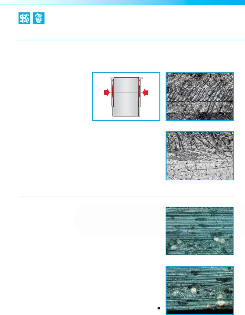
3.10.5 Brightly polished areas in the upper part of the cylinder
Description of the damage
In its upper area, the cylinder running surface has highly polished, bare areas in which the honing structure is completely unrecognisable (Fig. 1 and Fig 2). There are no significant signs of wear on the piston itself. The engine is consuming increased quantities of oil.
Fig. 2
Fig.1
Fig. 3
72 | Piston damages – Recognising and rectifying |
MSI Motor Service International |

Piston damages
Description – assessment – causes
Damage assessment
This type of damage pattern occurs when a hard oil carbon deposit forms in operation on the piston top land as a result of burned oil and combustion residues (Fig. 3). This coating has abrasive properties which lead to increased wear in the upper part of the cylinder in operation due to the reciprocal motion and the change of bearing surfaces of the piston. The in-
creased oil consumption is not caused by the polished areas themselves,
as the polished areas do not cause a noticeable out-of-roundness of the
cylinder, and the piston rings can still continue to perform their sealing duties in the normal fashion. The lubrication of the cylinder is also unaffected, as it is still possible to retain enough oil in the open graphite veins of the cylinder surface despite the loss of the honing structure. When assessing this type of damage, it is important to note that, in this case, the polished areas all coincide with points in the cylinder which come into contact with the carbonised piston top land. If the polished areas are also present at
points which do not come into contact with the piston top land, then the cause for the damage is more likely to be found in distortion of the cylinder (point “3.10.4 Uneven cylinder wear”), fuel flooding (point “3.11.3 Wear on the pistons, piston rings and cylinders caused by fuel flooding”) or ingress of dirt or contaminants (point “3.11.2 Wear on the pistons, piston rings and cylinders caused by the ingress of dirt”).
Possible causes for the damage
•Excessively high ingress of engine oil into the combustion chamber due to a defective turbocharger, inadequate oil separation in the engine breather, defective valve stem seals etc.
•Excessive pressure in the crankcase due to increased emissions of blowby gases or due to a faulty crankcase breather valve.
•Inadequate finishing of the cylinder, resulting in increased ingress of oil into the combustion chamber (see also point 3.11.4 Piston ring wear soon after a major engine overhaul).
•Use of non-approved engine oils or engine oils of a lower quality.
|
|
|
MSI Motor Service International |
Piston damages – Recognising and rectifying | 73 |
|

Piston damages
Description – assessment – causes
3.10.6 Cylinder liner fracture due to hydraulic lock
Description of the damage
The cylinder liner displays severe damage due to a crack in its upper area, together with seizure marks on the running surface (Figs. 1 and 2). The associated piston also displays seizure marks on the pressure and counterpressure side. A trough-
shaped indentation in the piston
crown has formed in the area where Fig. 1 the seizure marks are present on the
skirt (Fig. 3).
Fig. 2 |
Fig. 3 |
Fig. 4
74 | Piston damages – Recognising and rectifying |
MSI Motor Service International |

Piston damages
Description – assessment – causes
Damage assessment
The cylinder has suffered a hydraulic lock in operation. The high pressure from the liquid has burst the cylinder liner and pressed an a dent the piston crown. As a result, the piston mate-
rial has been squashed outwards, causing a significant restriction of the clearance in this area and the seizure marks on both sides of the piston and the cylinder liner. It can no longer be
identified whether the hydraulic lock occurred while the engine was running or while it was being started.
Possible causes for the damage
•Accidental intake of water while driving through high water, puddles or low rivers/waters, or as a result of larger quantities of water being splashed up by passing vehicles or vehicles in front.
•Cylinder filling up with water while the engine is stationary due to leaks in the cylinder head gasket or due to cracks in components.
•Cylinder filling up with fuel due to leaking injectors while the engine is stationary. The residual pressure in the fuel injection system is dissipated through the leaking nozzle into the cylinder. In this case and the one above the described damage will occur when the engine is started.
|
|
|
MSI Motor Service International |
Piston damages – Recognising and rectifying | 75 |
|

Piston damages
Description – assessment – causes
3.11 Increased oil consumption
3.11.0 General information on oil consumption
The total amount of oil used by an engine is primarily made up of oil consumption (i.e. oil burned in the combustion chamber) and oil loss (i.e. leaks). In contrast to still prevailing and widely-held views, oil consumption due to oil passing the pistons and piston rings into the combustion chamber plays a far less important role today.
As a result of the continuous development of engines, the design of individual parts, material compositions and production processes have been improved and highly optimised. For this reason, the effects of wear on cylinders, pistons and piston rings and the resulting increase in oil consumption are among the more negligible concerns on a modern engine. This is underlined by the high mileages which can currently be achieved and the reduction of incidents of damage to the crankshaft drive.
Although the oil consumption due to oil which passes between the piston rings and the cylinder wall into the combustion chamber cannot be completely eliminated with technical means, it can however be minimised. The moving parts (piston, piston rings and cylinder running surface) require continuous lubrication to ensure fric-
tionless and smooth operation. During the combustion stage the remaining oil film on the cylinder wall is subjected to the heat of the combustion. The quantity of oil which evaporates or burns here depends on the power output of the engine, the engine load and the temperature. Guide values for normal oil consumption are in the range from 0.2 to
1.5 g/kWh (max.).
In the majority of cases, wear on pistons, piston rings and cylinders and the resulting increased or excessive consumption of oil is not caused by
the components themselves. Instead, wear on these components can nearly always be explained as the result of an external event. Abnormal combustion due to incorrect mixture formation, dirt entering the engine from outside, inadequate engine cooling, lack of oil, incorrect oil grades and errors made during installation are the main reasons for premature wear and, subsequently, increased oil consumption. The following pages contain detailed descriptions of different types of damage which affects pistons, piston rings and cylinders.
Due to the complexity of the whole |
booklet are: |
• excessively high oil levels |
topic of oil consumption, a separate |
• excessive bearing clearance in the |
• abnormal combustion and fuel |
booklet entitled “Oil Consumption |
turbocharger |
flooding |
& Loss of Oil” has been published |
• blocked oil return line on the turbo- |
• incorrect piston protrusion |
in the Service Tips & Information |
charger |
• irregular servicing / maintenance |
series. Ordering information can be |
• worn fuel injection pumps |
• use of sub-quality mineral oils |
found in the appendix attached to this |
• oil leaks into the intake system |
• cylinder distortion |
document. The topics covered in the |
• worn valve stem seams and valve |
• machining faults during boring and |
|
guides |
honing |
|
• errors made during installation of |
• graphite exposure rate too low |
|
the cylinder head |
• twisted/distorted connecting rods |
|
• excess pressure in the crankcase |
• broken/jammed/incorrectly in- |
|
|
stalled piston rings |
76 | Piston damages – Recognising and rectifying |
MSI Motor Service International |

Piston damages
Description – assessment – causes
3.11.1 Incorrectly installed oil scraper ring (increased oil consumption after engine repairs)
Fig.1
|
green colour mark |
red colour mark |
|
assembly recommendation |
|
joint overlapped |
|
blade ring |
|
|
expander spring |
|
|
blade ring |
Fig. 2 |
Fig. 3 |
|
Description of the damage
The rings do not display any visible or measurable wear. No signs of wear are evident on the pistons either (Fig. 1).
In this case, the oil scraper ring is a 3 piece oil control ring comprising the expander spring and the two blade rings. Both of the ends of the expander spring should normally be flushed against each other. In this case the expander spring had been installed incorrectly, and the last segment overlapped at the joint (Fig. 2).
Damage assessment
Due to the overlapping of the ends |
the blade rings. The blade rings are |
|
of the expander spring during instal- |
then no longer pressed tightly against |
the combustion chamber, where it is |
lation, its circumferential length is |
the cylinder wall, and as a result the |
burned. Excessive oil consumption is |
shortened and the tension is lost for |
oil scraper ring is no longer capable of |
a result. |
Possible causes for the damage
The mistake was already made when |
the ends of the spring are colour-coded, |
Caution! |
|
the piston and piston rings were |
for example green for the left end of the |
Both coloured parts of the expander |
|
installed in the cylinder bore, as care |
joint, and red for the right end of the |
spring must be visible after installa- |
|
was not taken to ensure correct instal- |
joint. |
tion of the blade rings. These colour- |
|
lation of the expander spring. Usually, |
|
coded marks should therefore always |
|
|
|
be checked (even on pre-assembled |
|
|
|
piston rings) before installation of the |
|
|
|
pistons in the cylinder bore (Fig. 3). |
|
|
|
|
|
|
|
|
|
MSI Motor Service International |
Piston damages – Recognising and rectifying | 77 |

Piston damages
Description – assessment – causes
3.11.2Wear on pistons, piston rings and cylinder running surfaces caused by the ingress of dirt (increased oil consumption)
Description of the damage
The piston skirt (Fig. 1) displays a milky-grey (buffed) wear pattern with fine, small longitudinal scratches on the piston top land and the piston skirt. The tool marks created during machining of the piston have been completely worn away from the skirt. Fig. 3 shows an enlarged section of the piston skirt on which this abrasive wear is clearly evident. The axial height of the piston rings has been substantially reduced because of the wear, and as a result the tangential tension has also been reduced. The edges of the compression rings (the first ring in particular) and the edges of the ring grooves are worn (Fig. 2). The sharp, oil-scraping edges of the piston rings have become frayed, leading to the formation of a burr (Fig. 4). In the microscopic enlargement,
Fig. 1 roll marks can be seen on the surfaces of the piston ring flanges. The cylinders have been worn into a bulged shape, with the largest diameter at approximately the centre of the ring running surface.
Fig. 2
Fig. 3 |
Fig. 4 |
78 | Piston damages – Recognising and rectifying |
MSI Motor Service International |
Piston damages
Description – assessment – causes
Damage assessment
Scratches on the piston and piston rings, a matt wear pattern on the piston skirt, roll marks on the ring flanges (Figs. 6 and 7) and a bulging cylinder wear (Fig. 5) are always the consequence of abrasive foreign bodies in the oil circuit. As the piston
rings are worn on the running surfaces and edges, they can no longer seal the cylinder sufficiently and can therefore no longer prevent oil from passing into the combustion chamber. At the same time, the pressure in the crankcase increases as a result of combus-
tion gases flowing past the cylinder. This excessive pressure can cause increased quantities of oil to escape through radial oil seals, valve stem seals and other sealing points.
Fig. 5 |
Fig. 6 |
Roll marks on the rings are caused by dirt particles which become lodged in the ring groove. As the piston ring rotates in the groove, it keeps running over the dirt particle and gradually creates the characteristic marks on the piston ring flanks.
Fig. 7
Possible causes for the damage
•Abrasive dirt particles which enter the engine with the intake air due to inadequate filtration, including:
•missing, defective, deformed or poorly maintained air filters
•leaking points in the intake system, such as distorted flanges, missing gaskets or defective or porous hoses
•Particles of dirt which are not completely removed during an engine overhaul. Parts of the engine are often blasted with sand or glass beads during an overhaul in order to remove persistent deposits or combustion residues from the surfaces. If the blasting materials become deposited in the material and are not cleaned out properly then they may work their way loose when the
engine is running, thus causing abrasive wear. Figs. 8 and 9 show this type of damage due to dirt. The images were recorded with polarised light under a microscope in our laboratory. Glass fragments and even entire beads of the glass used for blasting can be clearly seen.
•If the first oil change is performed too late, the abraded particles which are generated when the engine is run in are then spread through the oil circuit to the other moving parts where they cause more damage. However, the sharp oil-scraping edges of the piston rings are particularly prone to damage.
Fig. 8
Fig. 9
MSI Motor Service International |
Piston damages – Recognising and rectifying | 79 |

Piston damages
Description – assessment – causes
3.11.3Wear on pistons, piston rings and cylinder running surfaces caused by fuel flooding (increased oil consumption)
Description of the damage
The piston displays signs of wear on the piston top land and the piston skirt. Rubbing marks can already be seen on the piston skirt which are characteristic for dry-running due to fuel flooding. The piston rings display very severe radial wear (Fig. 1). Both of the webs (support surfaces) on the oil scraper ring have been completely worn down, which also indicates significant wear (Fig. 2 ). By comparison, Fig. 3 shows the profile of a new and worn oil scraper ring (double bevelled spiral expander ring).
Fig. 1
1 mm
Fig. 2 |
Fig. 3 |
80 | Piston damages – Recognising and rectifying |
MSI Motor Service International |