

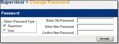
6.11.1 Change Password
This menu item enables the Supervisor to change the password. Tap to proceed. A pop-up window for new
password entry is presented, see Figure 94 below:
Each character of the new password entry
will appear in this window for verification
Use backspace key
to erase last entry as needed
Use number keys to enter new password
Tap to accept or cancel
Figure 94–Change password pop-up window
Figure 95–Change password web interface window
0350046-J0 Rev C
Page
90 of 127


Visit the Alpha website at www.alpha.ca for the latest manual and product downloads
7
7.1
Advanced Programming
Example: Customize
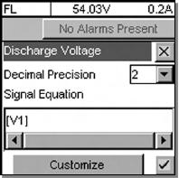
When configuring Alarms (Section 6.5.3), Signals (6.6.2), or Controls (0), an option to CUSTOMIZE will be
presented at the bottom of the screen, see Figure 96 below. This enables the Supervisor to program separate
triggering equations into the CXC software. The equations may reference any combination (up to 16) of the
analog inputs, digital inputs, virtual inputs, and alarms (such as Load Voltage shown below) utilizing logical and
arithmetic arguments that simulate the functionality of a programmable logic controller (PLC).
Mode (+Temp Comp) display
Name of item being edited
Battery Volts and
Load Current display
Discard changes and
return to previous screen
Use pull-down menu to change value
Equation displays here
Use slider to navigate/view as required
Whenever CUSTOMIZE is selected,
a keypad (similar to the virtual numeric
keypad) enables editing of the equation.
Accept changes and
return to previous screen
Figure 96–Screen showing example of item to be edited/customized
7.2
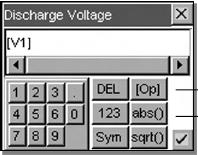
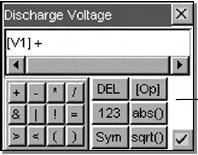
Equation Builder Keypads
Name of item/equation being edited
Cancel entry and close window
Equation displays here
Select [Op] for operand (pull-down menu)
Enter value as required
(similar to virtual numeric keypad)
Select abs() for absolute value function
[select sqrt() for square root]
Accept entry and close window
Figure 97–Equation builder keypad pop-up window
Tap to edit or enter a value. Use the virtual function buttons described above to navigate, cancel or accept.
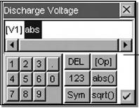
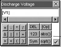
Item to be deleted is highlighted
Select DEL to remove item from
equation
Figure 98–Equation builder keypad delete key
0350046-J0 Rev C
Page
91 of 127


Refer to the back of this manual for Factory Service and Technical Support contact information
Mathematical operators:
+ = Add
- = Subtract
* = Multiply
/ = Divide
Keypad changed from numeric to symbol
Select Sym
for mathematical and logic operators
[select 123 to return to numeric keypad]
Figure 99–Equation builder keypad symbol key
Logical operators:
& = AND
| = OR
! = NOT TRUE
= is EQUAL THAN (compare for equality)
> is GREATER THAN
< is LESS THAN
( is OPEN PARENTHESIS (used with a
close parenthesis to set apart arguments to
Select + key for addition function
a mathematical function)
) is CLOSE PARENTHESIS (see open
parenthesis; used to clarify the order of
operations)
Figure 100–Equation builder keypad function keys
7.3
Tips on Programming
Square parenthesis [ ] are reserved for CXC signal names.
Use only round parenthesis ( ) for manipulating the order of operations in an equation.
The counters will increment approximately every half-second by default. A cascading counter can be written to
create a longer time between increments.
Here is a delay counter for AC fail alarm. The “AC Fail Delay” works by counting up from 0 to 30 when Rect. AC
Mains Fail alarm is true. When Rect. AC Mains Fail is false it will count down to 0.
[AC Fail Delay] + ( ( [AC Fail Delay] < 30) * [Rect. AC Mains Fail] ) - ( ( [AC Fail Delay] > 0 ) *
![Rect. AC Mains Fail] )
Here is a custom signal set up to filter the battery voltage. "Filtered Battery Voltage" is the custom signal name:
( ( [Filtered Battery Voltage] * 15 ) + [Battery Voltage] ) / 16
0350046-J0 Rev C
Page
92 of 127


Visit the Alpha website at www.alpha.ca for the latest manual and product downloads
8
8.1
8.1.1
CXC Communications Menu Parameters
This chapter provides definitions regarding Ethernet, IP Addresses, and CXC communications (port)
configurations.
Ethernet Port Configuration
About IP Addresses
IP stands for Internet Protocol. Every device on an IP-based LAN or WAN network (including the CXC controller,
as well as PCs, and routers) requires an IP address to uniquely identify the source node or destination node for
packets sent across the network. This applies to WAN and LAN connections. There are two ways of assigning an
IP address to a network device: Static IP Address and Dynamic IP Address.