

14.4. Calculation of gas turbine engine starting system
The purpose of the calculation is to determine the necessary maximum power of the starter, to build starting diagram and to determine starting duration.
14.4.1. Determination of necessary maximum power of the starter
This problem can be solved accurately provided the theory of power machines is applied.
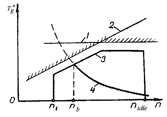
Fig. 14.4. Gas temperature in turbine inlet versus rotor rotational speed at starting:
1 – maximum permissible temperature under conditions of rotor details strength; 2 – maximum permissible temperature under conditions of compressor gas-dynamic stability; 3 – optimal law of gas temperature change at starting; 4 – gas temperature at steady-state starting ratings
In previous calculations necessary maximum power NSDmax of the starting device was determined using statistic data of the made constructions of starter. On the basis of these data specific power values of the starter are determined:
- for TJEs and TFEs
![]() ;
;
- for TPEs, ТPFEs, ТShEs and APUs
![]() ,
,
where Рmax [kN], Nmax [MW] are an engine thrust and power at maximum rating.
Specific power values of starters for different types of GTEs can be follows:
- for TJEs and TFEs with thrust less than 10 кN
![]() =
1,5...2,0 кW/кN;
=
1,5...2,0 кW/кN;
- for TJEs and TFEs with thrust more than 10 кN
![]() =
0,85...1,20 кW/кN;
=
0,85...1,20 кW/кN;
- for one-shaft TPEs with power less than 1000 кW
![]() =
30...50 кW/МW;
=
30...50 кW/МW;
- for one-shaft TPEs with power more than 1000 кW
![]() =
20...30 кW/МW;
=
20...30 кW/МW;
- for free turbine GTEs with power less than 1000 кW
![]() =
20...40 кW/МW;
=
20...40 кW/МW;
- for free turbine GTEs with power more than 1000 кW
![]() =
10...20 кW/МW;
=
10...20 кW/МW;
- for APUs
![]() =
80...100 кW/МW.
=
80...100 кW/МW.
Required starter power maximum values for the given types of the GTEs are calculated by the formulas:
NSD
max
=
![]() Рmax;
Рmax;
NSD
max
=
![]() Nmax
.
Nmax
.
The GTE starter maximum power, which is closest to objective value can be determined using specific power value of engine-prototype starter.
14.4.2. Starting diagram calculation
Starting diagram calculation lies in МSD(n), МR(n) and МТ(n) functions determination.
An equation of power and torque applied to an engine rotor is used at determination of the starter torque
![]() , (14.1)
, (14.1)
where is the engine rotor angular speed of rotation.
The
NSD(n)
function depends on the type of the starter used. For gas turbine
starters with a hydraulic clutch or differential reduction gear, as
well as for electric starters with a special voltage regulator, it is
possible to take МSD![]() М0=const
(Fig. 14.5).
М0=const
(Fig. 14.5).
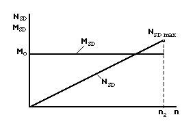
Fig. 14.5. Starter power dependence versus rotor rotational speed, for constant torque
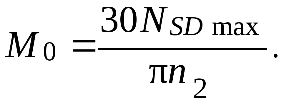
From an equation (14.1) for starter turn off rotational speed n2 we will get the formula of М0 constant calculation
![]()
The MSD linear lowering is typical of air-turbine starters and gas turbine starters with the free turbine at rotational speed magnification (Fig. 14.6)
МSD(n) = М0 – bn,
where М0, b are the constants, which have to be determined for the solution of the problem.
Using equation (14.1), we will get
![]() (14.2)
(14.2)
From the formula (14.2) follows that NSD = 0 at n = 0 and М0– bn = 0.
For function (14.2) maximum determination we will equate to zero its maiden derivative:
![]()
At
![]()
![]() NSD
= NSD
max.
NSD
= NSD
max.
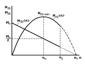
Fig. 14.6. Starter power dependence versus rotor rotational speed, for torque MSD linear reduction
From an equation М0–2bnМ=0 we determine rotational speed nМ, which corresponds to the maximum of starter power:
![]() (14.3)
(14.3)
Substituting values nМ in accepted linear dependence for МSD, we will get:
![]()
From equation (14.1) for МSD = М0/2 and n = nМ we will get
![]() (14.4)
(14.4)
From equation (14.4) the initial torque М0 of the starter is determined as:
![]() (14.5)
(14.5)
Constant “b” for a linear function МSD (n) can be got, when equation (14.5) is substituted in the formula (14.3):
![]()
For air turbine starters b=0,005…0,015 and for electric starters b=0,04…0,07.
The value nM is determined with the help of the statistic data through the rotational speed n2:
![]()
where k is a statistical factor.
For gas turbine starters, which have a free turbine k=1,5...1,6; for air-turbine starters k=1,8...2,0.
The MR engine rotor antitorque moment determination is solved according to the requirement of powers balance on the rotor at idling. The compressor creates main antitorque moment at starting. A part of power (not more than 5...7 %) is expended on the drive of engine units and overcoming of the friction forces in rotor support bearings. Thus, we can write down
MR(n) = (1,05...1,07) МCR,
where МCR is an antitorque moment of the compressor rotor, for which quadratic relation can be obtained
МCR = C n2, (14.6)
where C is a constant.
The power, which is spent on rotation of the compressor rotor at idling, is determined by known thermodynamics ratio
 (14.7)
where LAD C is an adiabatic work of the compressor at an idle; Ga is an air mass flow rate at the same rating; c is an efficiency of the compressor at idling.