

Fig. 14.8. Diagram of the redundant torque
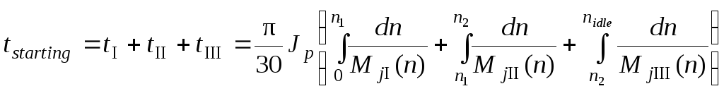
It’s advisable to compute the starting duration as the total of three stages durations
 .
(14.12)
.
(14.12)
The integrals in the formula (14.12) can be found by numerical methods, for example, method of rectangles, according to which the interval of integration is divided into some segments, and the summation of products of an integrand function discrete values and finite increment of rotational speed Δni is then designed.
The scheme of dissecting into segments of the redundant torque diagram is adduced in Fig. 14.6.
The formula of a numerical integration for the first stage of starting looks like:
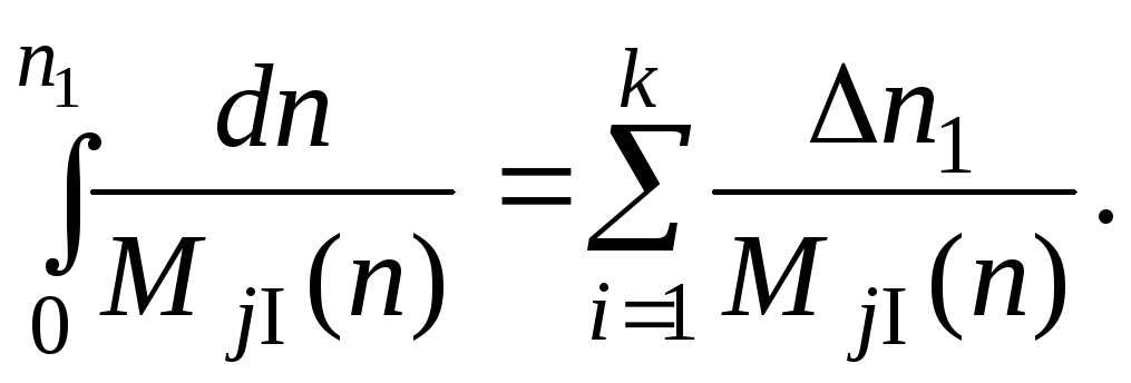
For the first and second stages of starting with a rather smooth variation of the torque МJ the adequate accuracy of a numerical integration can be obtained for a number of segments k=3...4, and for the third stage – at k = 5...6.
14.5. Types of aeroengine starters
The starter of any type consists of the power generator (engine), which through the reduction gear and the clutch gear with the GTE accessory gear elements transmits a torque to its rotor. The clutch gear is intended to disconnect a starter driving shaft after its switching-off from an engine accessory gear. In such mechanism free wheel clutches are usually applied (for example, roller free wheel coupling or ratchet coupling).
Depending on the type of the used power generator the starters are divided into three classes (Fig. 14.9):
- electrical (electric motor starters);
- turbine;
- hydraulic.
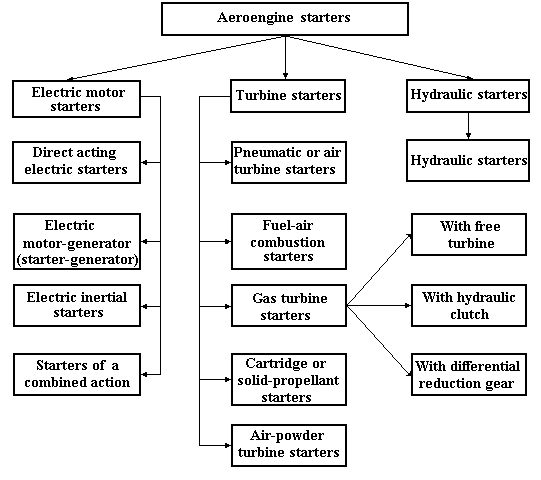
Fig. 14.9. Types of aeroengine starters
For piston aeroengines, auxiliary power units and low-powered turbine engines starting electrical starters are, as a rule, applied. The turbine starters are applied for starting different types of sustainer engines. The hydraulic starters, despite their small weight, are not widespread in starting systems of modern turbine engines.
14.5.1. Electrical starters
The electrical starters can be of the following (Fig. 14.9):
- direct acting electric starters;
- starter-generators;
- electric inertial starters;
- electric starters of a combined action.
Direct acting (cranking) electric starter is an electromotor of a direct current with power from storage batteries, which accelerates the started engine rotor through the reduction gear and free wheel clutch. Roller free wheel clutch (jaw or sprag clutch) (see Fig. 14.10 and Fig 14.12, b), axial ratchet clutch (Fig. 14.11) or pawl-and-ratchet clutch (Fig. 14.12, a) does not provide transmission of a torque from an engine rotor to starter rotor after its switching-off (over-running clutch). Direct acting electric starters (Fig. 14.13 and Fig. 14.14) are applied at small indispensable powers, which are sufficient for starting low-powered turbine engines and auxiliary power units (NSD =3...5 kW). At increase of starter power the weight of a starting system sharply increases.
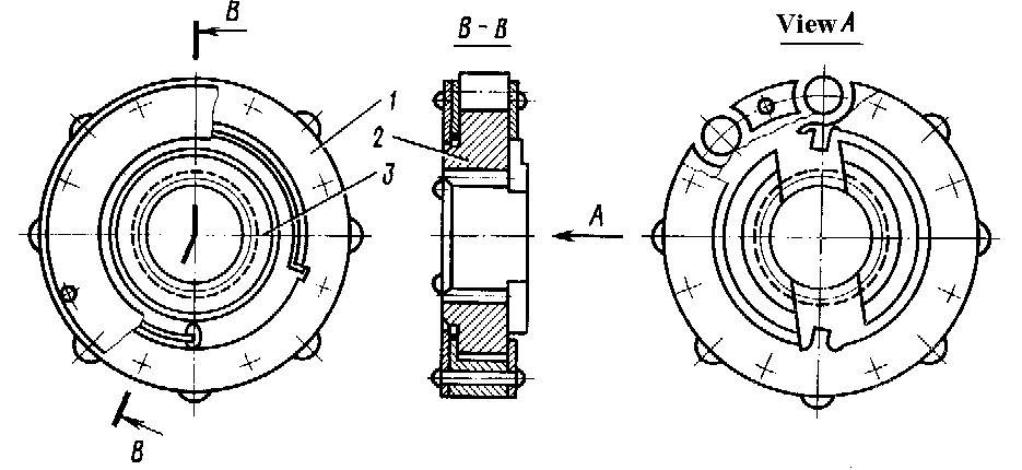
Fig. 14.10. Roller free wheel clutch:
1– separator; 2– sprocket roller; 3 – spring
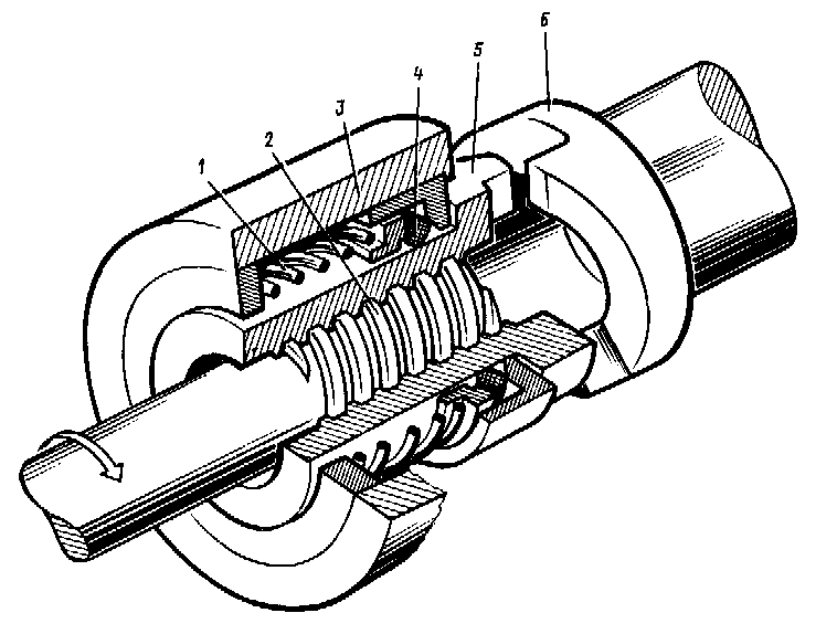
Fig 14.11. Axial ratchet clutch:
1 – spring; 2 – screw groove; 3 – clutch casing; 4 – felt ring; 5 – driving ratchet; 6 – driven ratchet

Fig. 14.12. Starter engaging mechanisms are needed to transmit starter torque
to the engine and provide a means of a disengaging the starter from the engine
when starter operation is not required:
a – pawl-and-ratchet clutch; b – sprag clutch
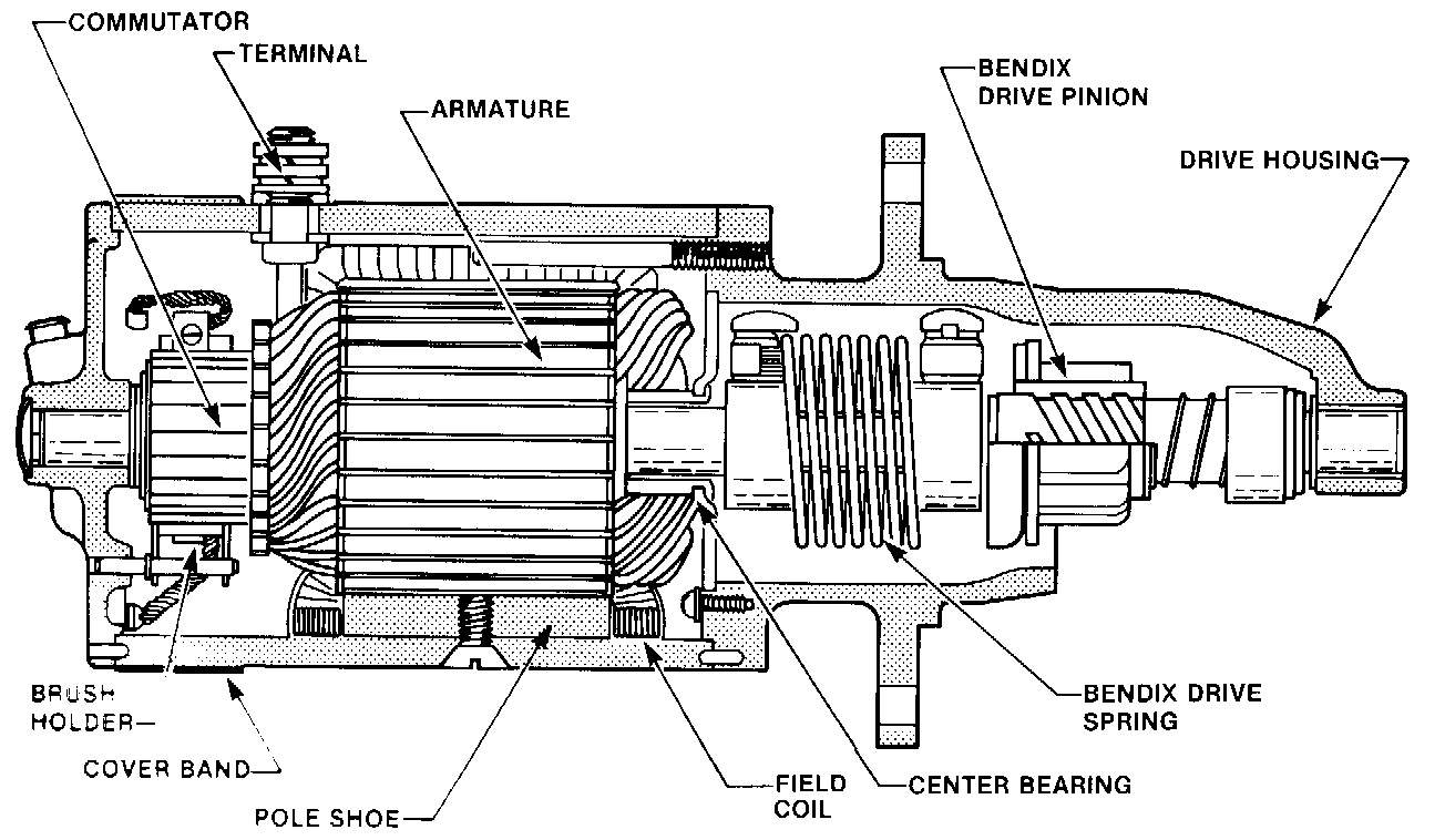
Fig. 14.13. Cutaway view of an aircraft starter using a Bendix drive
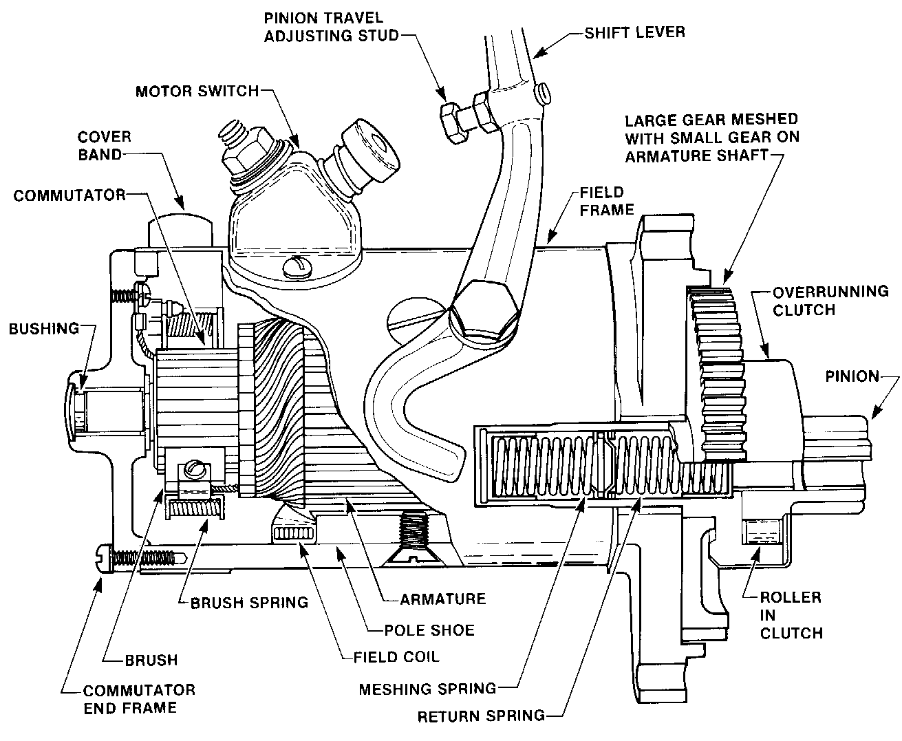
Fig. 14.14. Cutaway view of a direct-cranking starter using an over-running clutch
The starter-generator during engine starting works as direct electric starter with a planetary reduction gear (ref. 5, 7, 8 and 9 in Fig. 14.15) and clutch gear (ratchet clutch 3, 4). When starter-generator is no longer in starter rating (no power supply) it works as a direct current generator, which is driven directly from an engine accessory gear. The reduction gear of the starter-generator is disconnected at a generator rating with the help of the ratched clutch. After that a free wheel clutch 2 directly connects output shaft with an electromachine rotor shaft.
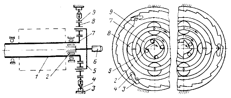
Fig. 14.15. Starter-generator kinematic scheme:
1 – anchor shaft; 2 – roller free wheel clutch; 3 – pawl-and-ratchet clutch fixed ring; 4 – pawls of ratchet clutch; 5 – planet carrier; 6 – drive shaft; 7 – driving gear; 8 – satellite; 9 – fixed gear
The starter-generators are applied at starter indispensable powers of 30...60 kW. At starter-generator power increase the starting system shows inadmissible increase in its weight.
The electrical starters of two types are applied for the piston aeroengine starting: electric inertial starters and starters of a combined action.
During piston aeroengine starting it is enough to make 1…2 revolutions of a crankshaft with rotational speed of 70...80 r/min. At the initial moment of crankshaft rotation it has considerable resistance, which is connected with large compression in cylinders. Therefore, for piston aeroengine starting the inertial starters are applied, which have large initial torque.
Electric inertial starter has the direct current electromotor of low power, which through roller free wheel clutch 7 (Fig 14.16) spins up a flywheel 8 of large weight up to rotational speed of 10000...12000 r/min. After that the electromotor is disconnected. Due to freewheel clutch 7 the torque from a flywheel is not transmitted to the electromotor rotor. The accumulated kinetic energy of a flywheel is used to transmit torque through the reduction gear 10 and friction coupling 4 (overriding clutch) to a starter output shaft, on which the ratchet 1 for connection with a crankshaft ratchet is installed. These ratchets are connected with the help of the electromagnetic relay assembly of coupling, or manually – with a roop 6.
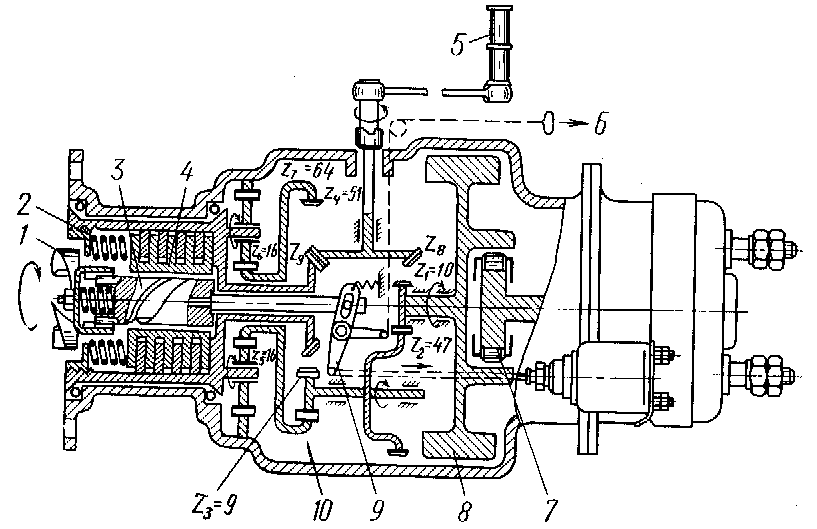
Fig. 14.16. Kinematic scheme of electric inertial starter РИМ-У-24ИР:
1– ratchet;2– friction clutch spring;3,9– clutch mechanism;4– friction clutch;5– shift lever;6– hand-operated switch rope of ratchet;7– roller free wheel clutch;8– flywheel;10– reduction gear
The friction coupling limits the value of a maximum torque on starter output shaft. It protects starter and crankshaft ratchets from destruction at the moment of electrical inertial starter output shaft connection with an engine crankshaft.
Starters of a combined action have the electromotor with rather large power. After flywheel overspeeding the electromotor is not disconnected. The total torque of the rotating flywheel and electromotor rotor is transmitted to starter output shaft, which is rigidly connected with a flywheel. The other units of a starter of a combined action are the same, as in electric inertial starter:
- reduction gear with large gear ratio;
- friction coupling;
- clutch gear of starter ratchet with an engine crankshaft.
Relative weight of a combined action starter flywheel is smaller, than an electric inertial starter is.