

Matta, Boyd. The quantum theory of atoms in molecules
.pdf502 19 Fleshing-out Pharmacophores with Volume Rendering of the Laplacian of the Charge Density
in matter manifested as topological features in the Laplacian of the charge density [6–10].
A wry observation by G.N. Lewis, on receipt of the Franklin Medal, bears repeating here. He wrote ‘‘It is always of interest to find that some of our most modern scientific ideas have been vaguely anticipated by scientists of earlier centuries. One of the ideas of Lemery, a contemporary of Robert Boyle, is amusingly discussed in a well known history of chemistry, as follows: ‘Yet one of his theoretical conceptions was very odd, and shows how far astray a capable man may wonder, when he deserts observed facts for philosophical speculations. He thought that chemical combination between two substances, such as an acid and a base, might be accounted for by supposing that the particles of the one were sharp, and those of the other porous, and that chemical combination was e ected by the fitting of the points into the holes!’ ’’ [11].
‘‘Fitting’’ incurs the need to measure both size and shape. This is easy for a tailor, but topological features in the Laplacian are challenges to the design chemist. It is quite tedious, and of uncertain significance, to exhaustively partition the entire Laplacian distribution into attractor basins, in a manner analogous to atomic partitioning [3, 12]. Qualitative assessments of feature size and shape are easily performed, and are informative, especially within a series of related molecules. These typically employ contour diagrams of the Laplacian, or iso-value surfaces, for example the outer ‘2r ¼ 0 ‘‘envelope’’. Contour diagrams can characterize both size and shape of features, but one ‘‘slice’’ at a time. For molecules of low symmetry, this is troublesome. The utility of Laplacian envelopes is not hindered by low symmetry, but the extent of size and shape characterization is limited by selection of a single value of the Laplacian.
Volume rendering [13] enables a continuous range of Laplacian values, or any other scalar data, to be visualized over a three-dimensional volume of any size. The complete occlusion of valence shell charge concentration (VSCC) features ‘‘inside’’ the valence shell charge depletion (VSCD) that surrounds all molecules, for instance, is prevented by a tunable ‘‘opacity transfer function.’’ In our implementation of this graphical technique [3], this function can be adjusted interactively with superimposed Gaussian and step functions. It has the e ect of rendering volume elements in 3D texture memory as opaque, invisible, or with adjustable levels of translucence. The rendering color is keyed to the value of the Laplacian at that point, with warmer colors indicating greater local concentration of electronic charge (white > red > orange > yellow), and cooler colors indicating greater local depletion of electronic charge (violet > blue > green). In much the same way as dye-stained organelles in a cell come into and out of focus under the microscope, topological features that are associated with reactive sites, for example lone pairs, can be probed for size and shape in three dimensions.
The results are useful and visually satisfying, providing a ‘‘holistic’’ method of molecular visualization that not only resonates with what chemists intuitively imagine molecules to be like, but have appealing aesthetic qualities that garishly-colored mirrored balls and golden rods do not [14]. Figure 19.2 is a workstation screenshot of the purine base adenine being rendered with our volume

19.2 Computational and Visualization Methods 503
rendering software, nicknamed EVolVis, for Electronic Volume Visualizer. Minimum hardware requirements, and details of the program’s algorithm, which uses OpenGL and the X Window system, are given in Ref. [3].
Those who are familiar with Laplacian distributions, will immediately see that this one image provides more information than multiple Laplacian envelopes, or a very large number of contour diagrams, all of which must be mentally collated to furnish a full 3D mental image of the molecule. The frame shown yields simultaneous rendering of lone pair features, for example on the three imine nitrogen atoms (bulbous red protrusions), the deep p charge depletions above and below the carbons (blue balls), and the shallow charge depletions behind the amino hydrogen atoms (little green ‘‘yarmulkes’’). Adjusting the appropriate slider bar can ‘‘grow’’ the orange VSCCs (new growth becoming ‘‘cooler’’ in color) until the p holes ‘‘close’’. The last carbon to do so must have the greatest local depletion at the corresponding ring CPs, thus implying the greatest susceptibility to attack by nucleophiles.
Figure 19.3 is a volume rendering of ‘2r for penamecillin, the molecule that was shown schematically in Fig. 19.1. The color key is as in Fig. 19.2, but the transfer function has been adjusted to contrast the hydrophilic diester chain (top right) and the hydrophobic aromatic ring (bottom left), and to bring into focus the key features on the perimeter of the reactive pocket (bracketed by the aromatic ring). There are 22 hydrogen atoms in this molecule, but only one is predicted by the ‘‘N, O, F rule’’ to be a hydrogen-bond donor. This amide hydrogen is jutting into the reactive pocket and is, indeed, revealed to have the only small charge depletion (green yarmulke) that is seen at the ‘‘appropriate’’ sites in adenine (Fig. 19.2). The sulfur atom also borders the reactive pocket, and its twin lone pair charge concentrations (orange) are rendered quite di erently from those of any of the oxygen atoms. One of the sulfur atom’s large charge depletions is also exposed to the reactive pocket, creating a chemically anisotropic environment for whatever fills it. This anisotropy is, literally, a highly varying ‘‘texture’’ which is naturally rendered by the Laplacian of the charge density.
The pharmacophore in Fig. 19.1, along with the rest of the molecule, is fleshedout in Fig. 19.3, but it is impossible to attribute pharmacological significance to the physical features that are revealed. Comparing the full, fleshy details of the pharmacophore in an active drug with those in an inactive drug would be an excellent opportunity to learn something about the pharmacological significance of the sizes and shapes of topological features in the Laplacian.
Wagner et al. have reported crystallographic studies of penamecillin and its partially oxidized sulfoxide (the only di erence is that one of the lone pairs is replaced with an oxo ligand) [15]. Local oxidation can be expected to alter the electrostatic potential in the region of oxidation, which was indeed observed by Wagner et al., in addition to some conformational di erences.
We repeated the volume rendering procedure for the second penicillin derivative, again using the nuclear coordinates from the crystallographic investigations. Again, as might be expected, there are large areas of near-perfect transferability far from the site of oxidation, whereas there are gross di erences at the


19.2 Computational and Visualization Methods 505
sulfur. These same observations would be made by comparing the minimallyinformative pharmacophores that correspond to the two molecules. We are interested in the subtle, but chemically significant details that may be evident in the fleshed-out pharmacophores. By sequentially volume rendering the Laplacian distributions of the two molecules, such di erences can be identified, but we are back in a similar situation as before – having to mentally contrast separate renderings. Truly parallel renderings would be preferable.
19.2.3
The Hyperwall
The hyperwall [4] is simply a 2D array of flat-screen displays with each display driven independently by a graphics workstation and with all the workstations connected by a network switch. Single large images can be rendered on the aggregate display (‘‘powerwall mode’’), but we have found it generally more useful to display sets of related images (‘‘hyperwall mode’’). The sets can be laid out according to a single identifier or a pair (row, column), and the set members (slaves) may be functionally connected to each other and/or to a controlling terminal (master node) over the intervening network. This arrangement provides a large number of pixels (65 million in the current implementation) but retains a high level of system support (CPU, GPU, memory, disk) per pixel, so that multiple instances of resource-intensive graphics techniques, for example time-varying volume visualization, can be e ciently deployed in parallel. The simultaneous display of, and interaction with, such visualizations provides a high-bandwidth, information-rich exploratory environment that enhances the remarkable power of our own visual systems for detecting di erences, trends, outliers, and subtle patterns.
A powerwall is simply a very large image made up of multiple computer screens – the total information content is equal to the sum of its parts. By relating the information content of the screens, in a user-controlled manner, the hyperwall is a demonstration of the teamwork maxim.
19.2.4
Hyper-interactive Molecular Visualization
In Fig. 19.4, what distinguishes the hyperwall from a powerwall is not apparent. For one thing, it is a static picture. On a powerwall the screens can simply display distinct video streams, but on the hyperwall ‘‘blocks’’ of screens, or the entire 7 7 array, can be synchronized. It is also possible for the user’s interaction with one screen, or a row/column of screens, to refresh the data displayed on other screen(s). For example, one column could be a series of related molecules, and the cursor on the ‘‘master node’’ (left, foreground in Fig. 19.4) could move a small cube in a concerted manner within each molecule. Another column could display 3D scatter plots of data within the cube on the molecule of the same row.


19.3 Subatomic Pharmacophore Insights 507
Fig. 19.5 A volume rendering of ‘2r in the reactive pocket of the inactive penicillin derivative. The local charge depletion behind the amide hydrogen (green yarmulke, indicated by the arrow) is seen pulled to the right, interacting with the nearby oxo group in that direction (some key atoms in this region are identified). This image is a screenshot of column 3, row 2, from Fig. 19.4.
One possible reason for the inactivity of the oxidized derivative is revealed in column 5. The hydrogen-bond donor feature that is fully exposed in the reactive pocket of the active form (Fig. 19.3) is severely deformed by the nearby oxygen atom of the added oxo group (Fig. 19.5). Intra-molecular hydrogen bonding thus could interfere with this molecule’s pharmacological activity.
Filling the hyperwall with fleshed-out pharmacophores, and scrolling through libraries of drug molecules, all the while searching for insights such as those above, is an exciting prospective use of this combination of visualization techniques.
19.3
Subatomic Pharmacophore Insights
19.3.1
Hydrogen-bonding Donor Sites
In the first systematic study of hydrogen bonding orientations on the basis of topological properties of the Laplacian, Carroll et al. used HF as donor and a variety of bases as acceptors [16]. They found excellent agreement with reported geome-

508 19 Fleshing-out Pharmacophores with Volume Rendering of the Laplacian of the Charge Density
Fig. 19.6 Volume rendering of ‘2r in 6-hydroxy-2-aminopurine. A di erent color key was used, but the ordering is the same as that discussed in the text. Adapted from Ref. [3].
tries of such van der Waals complexes when the local charge depletion behind the hydrogen atom of HF was collinearly aligned with the nucleus of the base atom and its nonbonded charge concentration.
We have found that this topological feature of the donor hydrogen atom’s VSCD is usually not present when the XaH is not a rule-based donor hydrogen bond, and that, when present, its magnitude parallels that of expected hydrogen- bond-donor strength [3]. All the XaH bonds in Figs 19.2 and 19.3 are consistent in this regard. We note that it is not simply a rendering artifact. The VSCD topology behind the hydrogen atoms of most CaH bonds, and XaH bonds in general when X is less electronegative than H, is opposite to that of the yarmulkes. They are local ‘2r minima within the VSCD whereas the yarmulkes are local maxima.
The Laplacian for the hydroxy isomer of guanine is volume rendered in Fig. 19.6. There are four types of XaH bonds, and the presence and size of the yarmulkes behind each is consistent with its expected hydrogen bonding capacity or strength. As expected, the amino and imino features are very similar.
Within QTAIM, identification of reactive sites, and their characterization, is performed by topological analysis of ‘2r by virtue of its role in describing the energetics of many-electron systems in stationary states [1]. Such a modelindependent procedure cannot be expected always to conform to established rules. Figure 19.7 indicates that hydrogen-bond donor features are not only found ‘‘where expected’’. ‘‘Weak hydrogen bonds’’, that do not follow the standard ‘‘rules’’, are believed to frequently play important structural and mechanistic roles in biological processes. Important classes of such hydrogen-bond donors are CaH

19.3 Subatomic Pharmacophore Insights 509
Fig. 19.7 Volume rendering of ‘2r in methyl fluoride. Note the barely formed yarmulkes beyond each of the ‘‘activated’’ hydrogen atoms. The pink halo is the torus of nonbonded charge concentration corresponding to the three lone pairs on fluorine.
bonds in which the carbon atom is ‘‘activated’’ by a highly electronegative substituent, for example fluorine, or oxygen in aldehydes. Corresponding to weak H-bond donor strength, the yarmulkes behind the hydrogen atoms in methyl fluoride are barely formed (Fig. 19.7), but they are a topological change, relative to simple alkanes, induced by fluorine substitution.
With systematic studies, the existence, strength, and direction of hydrogenbond donor features in pharmacophore models could be simply augmented with knowledge gleaned from topological analyses of ‘2r. Similar pharmacophore improvement is envisaged for hydrogen-bond acceptor features, based on analogous topological studies of nonbonded charge concentrations. Such studies have been well-reported in the literature [6–10].
19.3.2
Inner-valence Shell Charge Concentration (i-VSCC) Features in Transition-metal Atoms
Within the context of the orbital model of electronic structure, when explaining the ground states of elements in the d-block of the nth row of the periodic table,

19.3 Subatomic Pharmacophore Insights 511
directionality to metal–ligand interactions than is seen in groups IA and IIA, without invoking covalence.
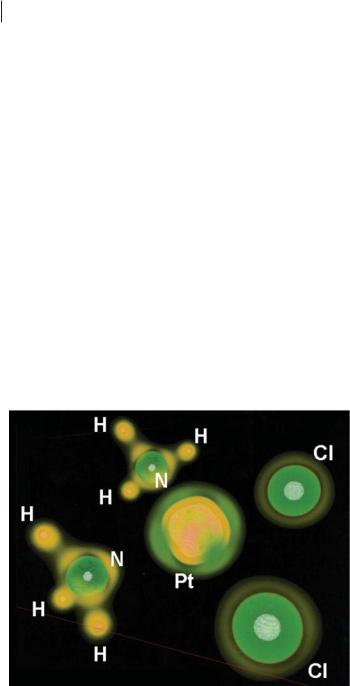
Because many enzymes have transition-metal ions at or near their active site, factors a ecting optimum coordination directions for di erent metals, and in their di erent oxidation states, may aid pharmacophore development. In much the same way as a hydrogen-bond donor feature in a pharmacophore includes a single, collinear arrow (Fig. 19.1), a Pt(II) feature could include four variously directed arrows. Ligand field theory suggests that they should be at 90 angles, anchored by permanent ligands, but volume rendering of ‘2r then topological analysis could refine these directions. These latter investigations may seem unnecessary if one assumes that the geometries of countless coordination complexes already imply optimum directions of metal–ligand bonding for di erent metal ions in their di erent oxidation states. This, however, is not always a valid assumption.
19.3.3
Misdirected Valence in the Ligand Sphere of Transition-metal Complexes
The geometry of chromyl chloride, CrO2Cl2, is ‘‘opposite’’, in a VSEPR model sense, from that of sulfonyl chloride, SO2Cl2. Both have distorted tetrahedral geometries, but the angle between the double bonds to oxygen are is smaller than the tetrahedral angle when the central atom is chromium, whereas it is larger (as expected) when the central atom is sulfur.
This and other geometric conundrums involving transition-metal atoms continue to be clarified by computational and experimental examination of the topological properties of the i-VSCC of the metal atom [17–20]. One reoccurring curiosity is that of misdirected valence.
Liehr coined the term ‘‘misdirected valence’’ in 1964 to improve the ligand theoretical predictions of the spectra of chelation complexes and other metallacycles [21]. If one ignores the metal atom that is chelated by a diamine, for instance, the shape around each nitrogen will be trigonal pyramidal, and the principal axes will be directed in the general direction of the metal atom. The ‘‘bite angle’’ of the ligand, and the size and d-electron count of the metal ion, will determine how ‘‘well-aimed’’ these axes are. Simple geometry-based corrections for misdirected valence greatly improved the accuracy of ligand field theory in such complexes [21].
Figure 19.9 presents stark physical, not inferred, evidence of misdirected valence. In CrO2Cl2, the stereochemical e ect of the ligand-opposed charge concentrations of chromium’s i-VSCC [18, 19] has narrowed the OCrO angle. In Fig. 19.9b the approximate twofold axis that is typically collinear with the MbO bond, and bisects the nonbonded charge concentrations in the VSCC of oxygen, is strongly askew. As indicated in Fig. 19.9b by the double-headed arrow, the local twofold axes, with regard to the structure of the VSCCs of the two oxygen atoms, are not directed at the chromium nucleus, but at the single charge depletion in the i-VSCD that apparently serves as the point of attraction for the oxygen ligands [18].