

ppl_06_e2
.pdfID: 3658
Customer: Oleg Ostapenko E-mail: ostapenko2002@yahoo.com
Customer: Oleg Ostapenko E-mail: ostapenko2002@yahoo.com
CH AP T ER 1 2 : V ACU U M SY
V a c u u m P u m p s .
Some early light aircraft (those built in the 1960’s) were fitted with ‘wet’ vacuum pumps like the one shown in Figure 12.6. Wet pumps used metal vanes which were lubricated with engine oil. Wet vacuum pumps wore out slowly and gradually and were very reliable.
Most modern light aircraft, since about 1970, have used what aretermed‘dry’vacuumpumpstopowertheirsuctionsystem.
They are called dry because they use self-lubricating graphite vanes which rotate within an eccentric aluminium cavity.
Dry vacuum pumps are generally very reliable. However, when they fail they do so catastrophically and without warning. To ensure that a failure cannot damage the engine’s
accessory drive, the pump drive incorporates a shear-coupling which will break if the pump’s input torque exceeds its normal operating figure by any significant amount.
If the drive does shear, then, of course, the gyro driven instruments will cease to function. To cover for this eventuality, some aircraft have an electrically driven auxiliary vacuum pump which will provide an independent back-up in the event of engine driven pump failure.
P r e s s u r e R e g u l a t o r .
Air driven gyro instruments are designed to operate with a pressure differential of about 5 inches of Mercury. Modern engine-driven vacuum pumps are designed to produce a large surplus of airflow through the instruments even when the engine is running slowly on the ground. At engine cruise RPM the pumps increase their capacity by a factor of 8 or more, and, as a consequence, if the suction were uncontrolled the gyros would be driven far too fast.
A constant airflow through the gyros is maintained by the pressure regulator, which admits sufficient air to leak into the system downstream of the gyros to limit the pressure differential across them to about 5 inches of Mercury. The pressure regulator in most systems is adjustable.
V a c u u m G a u g e .
The vacuum or suction gauge (Figure 12.8) is connected to read the pressure differential across the gyro instruments. Most suction gyro instruments require a pressure differential of 5 inches of Mercury to ensure that they operate correctly.
F i l t e r .
Ambient air enters the system through a vacuum filter. A representative inlet filter is illustrated in Figure 12.7. This ensures that the gyros are fed with only clean air that has had dirt and other contaminants removed from it.
When the filter is first fitted to the system there is almost no pressure drop across
it.
Figure 12.7 An Inlet Filter.
One disadvantage of a dry
vacuum pump is that it can fail catastrophically, and with no warning.
183
Order: 6026
Customer: Oleg Ostapenko E-mail: ostapenko2002@yahoo.com
Customer: Oleg Ostapenko E-mail: ostapenko2002@yahoo.com
CH AP T ER 1 2 : V ACU U M SY ST EMS
If a dry vacuum pump
system is not meticulously
cleaned after pump failure there is a danger that carbon fragments will re-enter it. If this happens the replacement pump will quickly fail.
If, with the gyro-driven instruments apparently
functioning normally and no low vacuum warning light, the suction gauge is showing system failure, the suction gauge is probably faulty.
SYSTEM MALFUNCTIONS.
Dry vacuum pumps are very vulnerable to contamination by liquids. The graphite vanes are designed to operate in an absolutely dry environment. If any form of liquid, for instance water, oil or engine cleaning fluid, gets into the pump, the vanes may be destroyed.
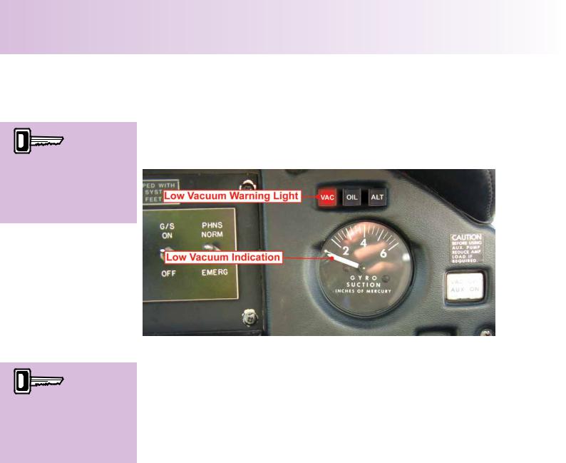
Figure 12.8 Two Types of Malfunction Warning.
Another form of contamination which will quickly destroy a dry pump is carbon. When a pump fails it will do so suddenly, generating a cloud of carbon fragments which can lodge in the outlet pipes of the pump. If the system is not meticulously cleaned when a replacement pump is being fitted, there is a danger that these fragments will fall back into it. If this is the case then the replacement pump will not last long.
Pump failure can also be brought on through overheating because the pump is having to work too hard to produce the required suction level. This can be the result of a partially blocked filter, or perhaps a hose in the system collapsing or having a kink in it. If the pressure regulator is adjusted to bring the system pressure back to its normal operating level then the pump will be working harder to produce the same results in the cockpit. A pump that is working too hard will run hot and will fail prematurely.
If there is a system malfunction, there are two indications in most aircraft cockpits to warn the pilot of vacuum system failure. They are the suction gauge and the low vacuum warning light, which are illustrated in Figure 12.8. A further clue to system malfunction may be the erratic operation of the gyro driven instruments.
If the Direction Indicator indicates to the pilot that the aircraft is not maintaining a steady heading, while the Attitude Indicator, at the same time, shows wings level then there may be a vacuum system malfunction.
If both instruments appear to be giving erroneous indications, then it is a fair assumption that the suction system has failed. System malfunction, of course, should already have been indicated to the pilot by the suction gauge and the low vacuum warning light.
184

ID: 3658
Customer: Oleg Ostapenko E-mail: ostapenko2002@yahoo.com
Customer: Oleg Ostapenko E-mail: ostapenko2002@yahoo.com
CH AP T ER 1 2 : V ACU U M SY
P r o c e d u r e s i n t h e e v e n t o f Ma l f u n c t i o n s .
If the pilot determines that his engine-driven vacuum pump has failed, and his aircraft |
|
|||
The electrical |
||||
is fitted with an auxiliary vacuum pump (see Figure 12.9), it should be selected ‘ON’. |
||||
A couple of words of caution however: |
|
load and the |
||
|
strength of |
|||
|
|
|
||
Firstly, be aware that the electrical load |
|
the magnetic field generated |
||
|
by the auxiliary vacuum pump |
|||
that these pumps place on the aircraft’s |
|
electric motor are quite high. |
||
electrical system is quite |
substantial. |
|
You may have to switch- |
|
It may be that the pilot will have to |
|
off unnecessary electrical |
||
consider switching-off unnecessary |
|
services. |
||
electrical services if he is obliged to |
|
|
||
select the auxiliary vacuum pump. |
|
|
||
Secondly, the strength of the magnetic |
|
|
||
field generated by the electric motor |
|
|
||
in the pump is such that it can cause |
|
|
||
compass errors. |
|
|
|
|
Some aircraft may have ‘inlet manifold |
|
|
||
suction’ fitted as a back-up to the |
|
|
||
normal vacuum system. |
It should be |
Figure 12.9. An Auxiliary Vacuum Pump. |
|
|
selected as a back up as soon as the
pilot determines that the engine-driven vacuum pump has failed. If there is no backup vacuum system fitted to the aircraft, the pilot will have to revert to the limited-panel flying technique.
185

Order: 6026
Customer: Oleg Ostapenko E-mail: ostapenko2002@yahoo.com
Customer: Oleg Ostapenko E-mail: ostapenko2002@yahoo.com
CH AP T ER 1 2 : V ACU U M SY ST EMS Q U EST IO NS
R e p r e s e n t a t i v e P P L - t y p e q u e s t i o n s k n o w l e d g e o f t h e V a c u u m Sy s t e m .
1.The engine driven vacuum pump is designed to produce and direct sufficient airflow:
a.Across a turbine that, in turn, drives the gyros
b.Through a helical impeller which drives the gyros
c.Onto gyro rotors to drive them round
d.Over the instrument case to move the gyro
2.The instruments usually powered by a vacuum pump system are:
(i)Direction Indicator
(ii)Turn Coordinator
(iii)Attitude Indicator or Artificial Horizon
(iv)Altimeter
(v)Magnetic Compass
a. |
(i) |
and |
(ii) |
|
b. |
(i) |
and |
(iii) |
|
c. |
(i) |
(iii) |
and |
(iv) |
d. |
(i) |
(iii) |
and |
(v) |
3.Which of the following is not a component of a dry vacuum system?
a.A vacuum generator
b.A vacuum controller
c.A filter to clean the air
d.A system lubrication device
4.One disadvantage of a dry vacuum pump when compared to a wet vacuum pump is that:
a.Dry pumps tend to be less reliable
b.Dry pumps fail catastrophically with no warning
c.Dry pumps require regular lubricating
d.Dry pumps are tolerant of contamination
5.On your instrument panel, the suction gauge is showing system failure. However, the gyro-driven instruments appear to be functioning normally, and the low vacuum warning light is out. The fault probably lies:
a.In the suction gauge
b.In the suction system
c.With the low vacuum warning light
d.In the gyro driven instruments
Questions 1 2 3 4 5
Answer
T h e a n s w e r s t o t h e s e q u e s t i o n s c a n b e f o
186

Customer: Oleg Ostapenko E-mail: ostapenko2002@yahoo.com
CHAPTER 13
ENGINE INSTRUMENTS
187

Order: 6026
Customer: Oleg Ostapenko E-mail: ostapenko2002@yahoo.com
Customer: Oleg Ostapenko E-mail: ostapenko2002@yahoo.com
CH AP T ER 1 3 : ENG INE INST R U MENT S
188

ID: 3658
Customer: Oleg Ostapenko E-mail: ostapenko2002@yahoo.com
Customer: Oleg Ostapenko E-mail: ostapenko2002@yahoo.com
CH AP T ER 1 3 : ENG INE INST R U
INTRODUCTION.
It would be very difficult to fly a modern light aircraft safely if there were no engine instruments to indicate to the pilot the state of the engine.
Some engine instruments, like those shown in Figure 13.1, are termed engine condition indicators. These include the Cylinder Temperature and Oil Temperature gauges and the Exhaust Gas Temperature gauge.
Figure 13.1 Engine Condition Indicators.
Other engine instruments are called performance indicators. Within this group are placed the Engine RPM Gauge and the Manifold Pressure Gauge, examples of which are shown in Figure 13.2. As their name suggests, these instruments are intended to show how well the engine is performing.
Figure 13.2 Performance Indicators.
Furthermore, without engine instruments, effective management of the engine would be impossible; the engine would not give long and efficient service and faulty operation would be commonplace.
It is, thus, essential that the engine instruments function correctly. The pilot must also be assiduous in monitoring the engine instruments.
Engine
condition indicators
include the Oil
Pressure and Oil Temperature gauges and the Exhaust
Gas Temperature gauge.
Performance
indicators include
the engine
RPM Gauge and the Manifold Pressure Gauge.
TEMPERATURE SENSING EQUIPMENT.
Piston engines are heat engines. The power they produce is directly proportional to the heat released during the combustion of the fuel. Engine components and systems are designed to withstand certain temperatures. If the temperature limits are exceeded, the components may fail.
189

Order: 6026
Customer: Oleg Ostapenko E-mail: ostapenko2002@yahoo.com
Customer: Oleg Ostapenko E-mail: ostapenko2002@yahoo.com
CH AP T ER 1 3 : ENG INE INST R U MENT S
In a wet-sump system, oil
temperature is normally
sensed where the oil enters the engine, after the oil has passed through the oil cooler.
The exhaust gas
temperature gauge
can be used to indicate mixture strength.
For safe operation, the engine temperatures must be monitored. The following temperatures are monitored on piston engines: oil, exhaust gas, and cylinder head.
O i l T e m p e r a t u r e
Monitoring the engine oil temperature is important from at least two points of view.
Firstly, the oil itself will retain its lubricating properties up to a certain maximum temperature. Above that temperature, the oil breaks down and the moving parts of the engine begin rubbing against each other, generating excessive heat. Engine failure quickly
follows. |
Figure 13.3 Oil Temperature Gauge - |
|
graduated in Degrees Fahrenheit. |
Secondly, the engine expends a percentage of its power forcing the oil into the bearings. The colder the oil, the larger that percentage of power will be. If the aircraft is to perform safely, the engine oil temperature must reach a certain level before the pilot can be sure that his engine is delivering the power to the propeller that the manufacturers intended.
In a wet-sump lubrication system, oil temperature is normally sensed at the point where the oil enters the engine, after it has exited the oil cooler. In a dry-sump lubrication system, the oil temperature is sensed between the oil cooler and the oil tank. In a typical engine oil temperature indicating system, the indicator is powered by the aircraft electrical system. An electrical resistance-type thermo-bulb, installed in the engine oil pump housing measures the temperature of oil entering that unit. The temperature reading is usually in degrees Celsius, although the example shown in Figure 13.3, from a Piper Warrior, is displaying the temperature in degrees Fahrenheit. The pilot must take particular care to ensure that the oil temperature remains within limits during a prolonged climb or glide descent.
Ex h a u s t G a s T e m p e r a t u r e G a u g e .
An exhaust gas temperature gauge, like the one shown in Figure 13.4, can show you whether your engine is running too lean or too rich.
An exhaust-gas temperature probe is installed about four inches from the cylinder head on the exhaust system. The probe is the junction of two dissimilar metals called a thermocouple. When a thermocouple is heated, a voltage is produced which is proportional to the temperature at the junction. The gauge, itself, is a millivolt-meter which is calibrated in degrees Celsius or Fahrenheit. Fahrenheit is still common in American-made light aircraft. Although
the exhaust gas temperature gauge can help in troubleshooting a problem on the engine, it is primarily a fuel management instrument.
190

ID: 3658
Customer: Oleg Ostapenko E-mail: ostapenko2002@yahoo.com
Customer: Oleg Ostapenko E-mail: ostapenko2002@yahoo.com
CH AP T ER 1 3 : ENG INE INST R U
Cy l i n d e r H e a d T e m p e r a t u r e G a u g e .
The Cylinder Head Temperature Gauge, of which an example is shown in Figure 13.5, is an engine instrument designed to protect the engine against excessive heat.
The principle of operation of the Cylinder Head Temperature Gauge system is similar to that of the exhaust gas temperature gauge. A probe consisting of two dissimilar metals, joined together to form a thermocouple, is mounted on the engine cylinder head. The probe transmits a voltage to the gauge in the cockpit which is proportional to the temperature sensed.
Most general aviation aircraft engines sample the cylinder head temperature of the hottest cylinder. The hottest cylinder is determined by extensive flight tests carried out by the engine manufacturers. Again, the pilot must ensure that the cylinder head temperature remains within limits in a prolonged climb (risk of overheating), or a prolonged descent (risk of overcooling).
Figure 13.5 A Cylinder Head Temperature
Gauge.
The cylinder
head temperature
gauge obtains
its temperature information from a thermocouple probe, which consists of the junction of two dissimilar metals.
PRESSURE-SENSING EQUIPMENT.
Di r e c t R e a d i n g a n d R e m o t e In d i c a t i n g In s t r u m e n
The function of many aircraft engine systems relies on the action of liquids and gases whose pressure must be measured and indicated to the pilot. The gauges and indicating systems fall into two categories: Direct Reading and Remote Indicating. Both of these systems are illustrated in Figure 13.6.
Figure 13.6 Direct and Remote Reading Gauges.
“Direct reading” describes the type of instrument used when the fluid that is being sampled is fed directly to the interior of the instrument positioned in the cockpit.
191

Order: 6026
Customer: Oleg Ostapenko E-mail: ostapenko2002@yahoo.com
Customer: Oleg Ostapenko E-mail: ostapenko2002@yahoo.com
CH AP T ER 1 3 : ENG INE INST R U MENT S
“Remote indicating” is where a separate sensing element is connected to a pressure source at some remote point and the information required is transmitted electrically to the instrument in the cockpit.
PRINCIPLE OF OPERATION OF PRESSURE SENSING
INSTRUMENTS.
Pressure is defined as force per unit area. In light aircraft engine instrument terms, it is normally indicated in either pounds per square inch (PSI), bars, or inches of mercury (in. Hg).
In engine pressure measurement, we are concerned with the following terms: Absolute Pressure and Gauge Pressure. Most pressure gauges measure the difference between the absolute pressure and the atmospheric pressure. This is Gauge Pressure. To actually measure pressure in a system, elastic pressure sensing elements are used, in which forces can be produced by applied pressures and converted into mechanical movement. The movement of these elements can then operate a direct reading gauge or an electrical transmitter. The sensing elements commonly used are diaphragms, capsules, bellows and bourdon tubes.
Di a p h r a g m s .
Diaphragms, like the one shown in Figure 13.7, consist of corrugated circular metal discs which are secured at their edge, and when pressure is applied they are deflected.
Diaphragms are used to measure relatively low pressures.
Ca p s u l e s .
Capsules, similar to the one shown in Figure 13.8, are made up of two diaphragms placed together and joined at their edges.
The device thus constructed can then be used to form either a sealed chamber, which is called an aneroid capsule, or a chamber which is communicated to a pressure source, which is called a pressure capsule. Capsules, like diaphragms, are also used to measure low pressure, but capsules are more sensitive to small pressure changes.
Be l l o w s .
The bellows type element, which is shown in Figure 13.9, can be considered as an extension of the aneroid capsule principle. It may be used for high, low or differential pressure measurement.
Note: “Aneroid” means “without liquid”.
Figure 13.7 A Diaphragm.
Figure 13.8 A Capsule.
Figure 13.9 A Bellows Element.
192