

ppl_06_e2
.pdfID: 3658
Customer: Oleg Ostapenko E-mail: ostapenko2002@yahoo.com
Customer: Oleg Ostapenko E-mail: ostapenko2002@yahoo.com
CH AP T ER 2 : CENT R E O F G R AV IT Y CAL
Before proceeding further, however, we must take a closer look at the concept of “moments”.
THE PRINCIPLE OF MOMENTS.
The moment of a force acting on a mass is defined as the turning effect that the force exerts about any defined axis, pivot point, or fulcrum.
Figure 2.6 A moment of 400 lb-ins acting clockwise on a 10 lb mass.
In Figure 2.6, we see a 10 lb mass suspended at 40 ins from a pivot-point, P.
For practical purposes, the weight of the mass may also be taken to be 10 lbs, so the turning effect, or moment, of the mass about the pivot, P, is quantified as being: 10 lbs X 40 ins = 400 lb-ins.
This moment of 400 lb-ins will, quite obviously, cause the beam, to which the mass is attached, to rotate clockwise.
Figure 2.7 Two moments of 400 lb-ins balancing each other.
The moment
of a mass is equal to
the force
acting on that mass times the distance of the mass from the pivot point, i.e. the point of rotation.
289
Order: 6026
Customer: Oleg Ostapenko E-mail: ostapenko2002@yahoo.com
Customer: Oleg Ostapenko E-mail: ostapenko2002@yahoo.com
CH AP T ER 2 : CENT R E O F G R AV IT Y CALCU LAT IO NS
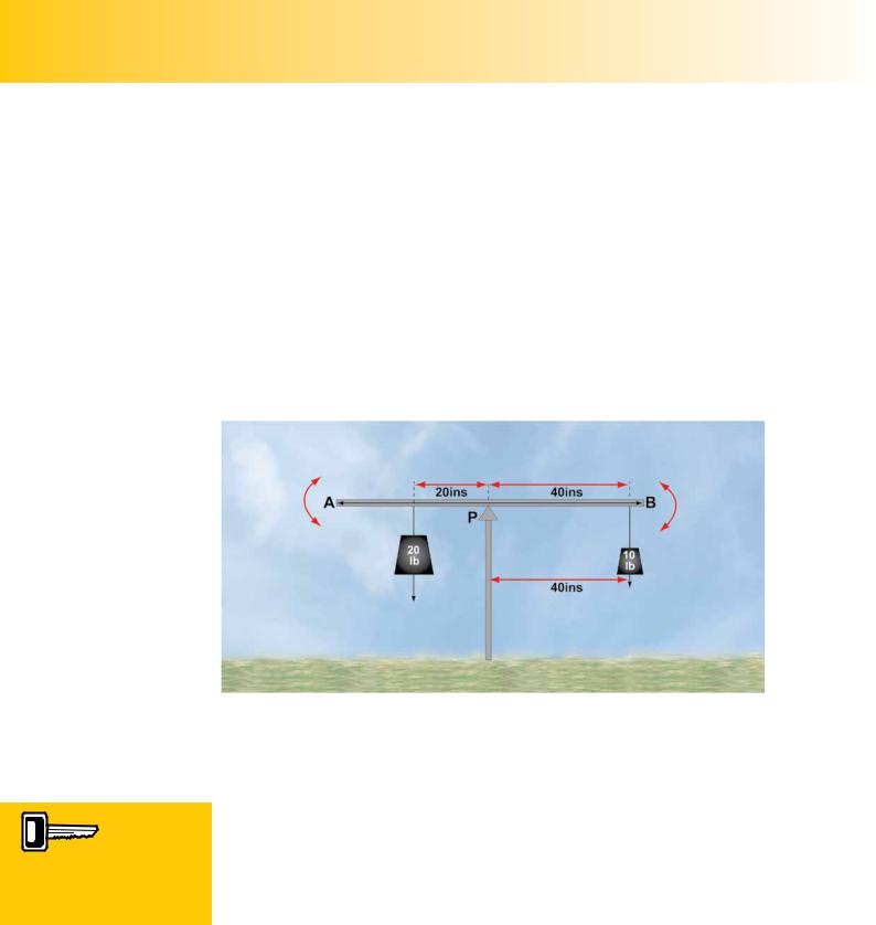
We can prevent that clockwise rotation by applying to the beam an equal and opposite turning moment of 400 lb-ins acting anti-clockwise. This could be achieved by hanging an identical 10 lb mass at 40 ins from the pivot, P, from the left hand side of the beam, as depicted in Figure 2.7.
However, the essential matter in balancing the original 400 lb-ins clockwise moment is not to have an identical mass suspended at an identical distance on the other end of the beam, but to create, in whatever way we can, a balancing moment acting anticlockwise, of 400 lb-ins. This could be achieved by suspending a 20 lb mass at 20 ins from the pivot, P, on the left hand side of the beam, as depicted in Figure 2.8.
The 20 lb mass, then, suspended at 20 ins from the pivot-point, P, has the same turning effect as a 10 lb mass suspended at 40 ins from the pivot-point. Both masses have a turning effect or moment of 400 lb-ins. So a mass of 20 lb with a moment arm of 20 ins has the same moment as a mass of 10 lb with a moment arm of 40 ins.
One important condition for
a body to be in equilibrium is that the clockwise moments
must equal the anticlockwise moments.
Figure 2.8 Two balancing moments, each of 400 lb-ins.
We could have found, by trial and error, that the 20 lb mass needed to be placed at 20 ins from the pivot, P, in order to balance the beam, or we could have calculated its position. Let us look at the calculation.
In order to balance the clockwise moment of 400 lb-ins, we know we need an anticlockwise moment of the same value. So, for balance:
Clockwise moment = Anti-clockwise moment
So, |
400 (lb-ins) = 20 (lb) X x (ins) ....... |
1 |
where x is the unknown moment arm at which the 20 lb mass must be placed to achieve balance.
290
ID: 3658
Customer: Oleg Ostapenko E-mail: ostapenko2002@yahoo.com
Customer: Oleg Ostapenko E-mail: ostapenko2002@yahoo.com
CH AP T ER 2 : CENT R E O F G R AV IT Y CAL
By simple mathematical transposition we can see from equation 1 that:
x (ins) |
= |
400 (lb-ins) |
|
|
20 (lb) |
Therefore, |
x = |
20 ins |
So, to find the moment arm of the 20 lb mass, required to balance the beam, we simply divided the clockwise moment, 400 lb-ins, by the mass, 20 lb.
Ca l c u l a t i n g t h e P o s i t i o n o f t h e P i v o t - P o i n t P .
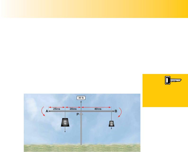
There is one, final, important matter to note. Because, in Figure 2.8, the beam is in equilibrium and the total magnitude of the downward acting force (weight) acting on the two masses is 30 lb, an upwards acting force of equal magnitude, 30 lb, must act at the pivot-point, as depicted in Figure 2.8b. If it did not, the beam would fall to the ground.
Figure 2.8b An upwards-acting force of 30 lb, at P, balances the 30 lb force (20 lb + 10 lb) acting downwards.
We can see, then, that when the beam is not rotating (that is, when the beam is in equilibrium), the moments balance each other out, the clockwise moment having the same magnitude as the anticlockwise moment, and the downward-acting forces are equal to the upward-acting forces.
For equilibrium, it is not important that a particular mass be placed at a particular distance from the pivot-point. Whatever mass we use, and wherever we position it, it only matters that the moment should be of the correct magnitude and act in the correct direction. We have seen that a 10 lb mass hung at 40 ins from a pivot-point produces the same moment (turning effect) as a 20 lb mass hung at 20 ins from the pivot-point.
Because the beam is in equilibrium and not turning, with the clockwise and anticlockwise moments in balance, we could, if we wished, take moments about any datum point to express this state of equilibrium. The datum point need not even lie on the beam.
For a beam
to be in equilibrium,
the clockwise
moments must equal the anticlockwise moments, and the upwards acting forces must equal the downwards acting forces.
291

Order: 6026
Customer: Oleg Ostapenko E-mail: ostapenko2002@yahoo.com
Customer: Oleg Ostapenko E-mail: ostapenko2002@yahoo.com
CH AP T ER 2 : CENT R E O F G R AV IT Y CALCU LAT IO NS
Let us try out this theory. Let us take moments about Point A, in Figure 2.8b) at the left-hand end of the beam. We will assume that Point A is 25 ins from the 20 lb mass.
For equilibrium, of course:
clockwise moments = anticlockwise moments
Let us see if this is, in fact, true, by taking moments about Point A. First, we will calculate the clockwise moments.
clockwise moments = (20 lb X 25 ins) + (10 lb X 85 ins)
=500 lb-ins + 850 lb-ins
=1 350 lb-ins
Now we will take the anticlockwise moments. This will be the moment caused by the 30 lb upward-acting force at the Pivot P.
anticlockwise moment = 30 lb X 45 ins = 1 350 lb-ins
As we see, the anticlockwise moment does equal the clockwise moments, both having a magnitude of 1 350 lb-ins. So, our theory is proven:
To check for equilibrium, then, we may take moments about any datum we choose.
In fact, using this principle, we could calculate the value and position of P, for any combination of masses. For instance, if we replace the 20 lb mass by a 15 lb mass and move it to a position 20 ins from A (see Figure 2.8c), what would the magnitude of P have to be for equilibrium, and what distance must P be positioned from A?
Figure 2.8c Calculating the distance of P from A.
Well, we can easily calculate the magnitude of P. The total downward acting force (weight) is now 25 lb, so, P, the pivot-point, must be pushing upwards with a force of 25 lb. Now, what about the position of P with respect to A?
For equilibrium
292

ID: 3658
Customer: Oleg Ostapenko E-mail: ostapenko2002@yahoo.com
Customer: Oleg Ostapenko E-mail: ostapenko2002@yahoo.com
CH AP T ER 2 : CENT R E O F G R AV IT Y CAL
clockwise moments = anticlockwise moments
Taking moments about Point A:
clockwise moments = (15 lb X 20 ins) + (10 lb X 85 ins)
=300 lb-ins + 850 lb-ins
=1 150 lb-ins
anticlockwise moment = 25 lb X x ins, where x is the distance of P from A .
Therefore, for equilibrium 25 X x lb-ins = 1 150 lb-ins
So, x = 1 150 lb-ins = 46 ins 25 lbs
So, P, the pivot-point, must now be at 46 ins from A.
This, then, is the Principle of Moments. We can use the Principle of Moments to calculate the position of the centre of gravity of an aircraft in exactly the same way that we calculated the position of P from A, for a beam in equilibrium.
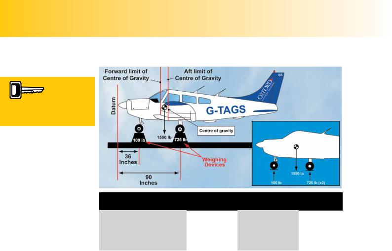
When we weigh an aircraft, as depicted in Figure 2.9 overleaf, the aircraft is static and motionless, and, so, is in equilibrium. Just as the pivot-point, P, exerts a force equal to the magnitude of the combined value of the forces acting on all the masses on the beam, the combined forces acting on all the masses making up the aircraft’s structure, equipment and loads will act through the aircraft’s centre of gravity, giving us the aircraft’s total weight.
If you examine the inset to Figure 2.9, you see that we have a measured reaction force acting upwards on the nose wheel of 100 lb, and a measured reaction force acting upwards on each of the two main-wheels of 725 lb. This means that the aircraft’s total weight acting downwards through its centre of gravity is 1550 lb.
The moments of all the aircraft’s constituent masses, therefore, can be entered into a
Principles of Moments calculation to determine the aircraft’s centre of gravity.
CALCULATION OF AN AIRCRAFT’S CENTRE OF GRAVITY FOR
ITS BASIC EMPTY MASS.
Overleaf, we reproduce the diagram and table that we need to calculate the aircraft’s centre of gravity (CG) for its Basic Empty Mass. This table is called the aircraft’s load sheet.
We can now complete the load sheet, overleaf.
293
CH AP T ER 2
The Principle of Moments
can be used to calculate the
position of an aircraft’s Centre of Gravity.
Order: 6026
Customer: Oleg Ostapenko E-mail: ostapenko2002@yahoo.com
Customer: Oleg Ostapenko E-mail: ostapenko2002@yahoo.com
: CENT R E O F G R AV IT Y CALCU LAT IO NS
ITEM |
MASS |
ARM |
MOMENT |
|
(lb) |
(ins) |
(lb-ins) |
Nosewheel |
100 |
36 |
3 600 |
Left Main Wheel |
725 |
90 |
65 250 |
Right Main Wheel |
725 |
90 |
65 250 |
TOTAL |
1 550 |
|
134 100 |
Figure 2.9 Calculating the aircraft’s CG for its Basic Empty Mass.
The moment about the datum of the upward reaction force acting on the nose-wheel is 100 (lb) X 36 (ins) = 3 600 lb-ins. Similarly, the moment about the datum of the upward reaction force acting on the left main-wheel is 725 lb X 90 ins = 65 250 lb-ins. The main right-wheel will, of course, exert the same moment of 65 250 lb-ins about the datum.
We can see, then, that there are three forces being measured by the weighing devices: the upward reaction forces acting on the nose-wheel and on the two mainwheels. We can also see from the table that the moment about the datum has been calculated for each one of these forces.
So, knowing that the total weight acting on the aircraft’s total mass will act downwards through the aircraft’s centre of gravity (CG), we can now calculate the position of the CG, by calculating the moment it would have about the datum, that would be equal to the three moments that we have already calculated.
From the table at Figure 2.9, we can easily find the total mass of the aircraft by adding together the readings from all three weighing devices. The total mass is 1 550 lb. The force acting on this mass is the weight of the aircraft, also expressed as 1 550 lb, which, as we have seen, acts downwards throught the CG.
We can also find the total, anticlockwise moment of the aircraft about the datum by adding up the three individual moments acting at each undercarriage leg. The total moment is 134 100 lb-ins.
294

ID: 3658
Customer: Oleg Ostapenko E-mail: ostapenko2002@yahoo.com
Customer: Oleg Ostapenko E-mail: ostapenko2002@yahoo.com
CH AP T ER 2 : CENT R E O F G R AV IT Y CAL
Now, because the aircraft is in equilibrium, the force acting on the total mass of the aircraft, 1 550 lb, must exert an equal and opposite clockwise moment of
134 100 lb.
We can now, therefore calculate the distance (moment arm) of the aircraft’s CG from the datum:
moment (lb-ins) = mass (lb) X moment arm (ins)
We can see, therefore, from simple mathematical transposition that:
moment arm (ins) = moment (lb-ins) mass (lb)
Consequently, the moment arm for the total weight of the aircraft acting on its total mass is given by:
moment arm (ins) = 134 100 (lb-ins) = 86.5 ins 1 550 (lb)
86.5 ins, then, is the distance behind the datum of the CG of the aircraft, through which the aircraft’s total weight acts on the aircraft’s total mass (by definition).
The completed load sheet for the aircraft’s Basic Empty Mass is at Figure 2.10.
ITEM |
MASS |
ARM |
MOMENT |
|
(lb) |
(ins) |
(lb-ins) |
Nosewheel |
100 |
36 |
3 600 |
Left Main Wheel |
725 |
90 |
65 250 |
Right Main Wheel |
725 |
90 |
65 250 |
TOTAL |
1 550 |
86.5 |
134 100 |
Figure 2.10 The completed load sheet for the aircraft’s Basic Empty Mass, showing its CG position: 86.5 ins aft of the datum.
This CG position for the Basic Emply Mass (BEM) is calculated by the aircraft manufacturer and will be entered in the Flight Manual and Pilot’s Operating Handbook. The manufacturer will, of course, ensure that this BEM CG position is within the permissible forward and aft limits for the CG. It is the pilot’s reponsibility to ensure that the CG remains within the permissible limits when the aircraft is carrying fuel, crew, baggage, etc.
The aircraft manufacturer defines the
fore and aft limits of the Centre of Gravity. It is the pilot’s responsibility to ensure that the position of the Centre of Gravity remains within the limits.
295
Order: 6026
Customer: Oleg Ostapenko E-mail: ostapenko2002@yahoo.com
Customer: Oleg Ostapenko E-mail: ostapenko2002@yahoo.com
CH AP T ER 2 : CENT R E O F G R AV IT Y CALCU LAT IO NS
MASS - CENTRE OF GRAVITY ENVELOPE.
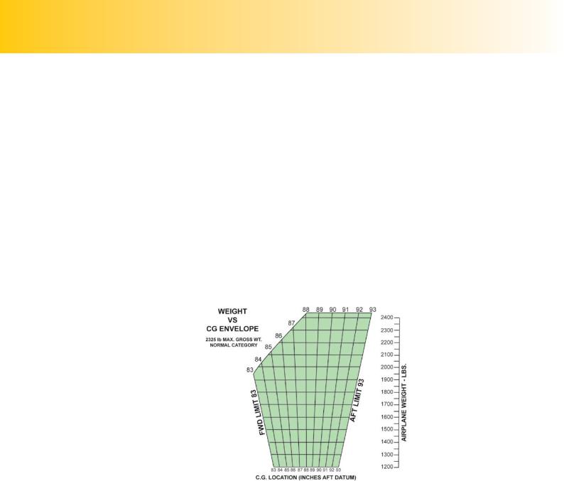
At the end of the design and testing process for a new aircraft, the manufacturer will produce a MASS - CENTRE OF GRAVITY ENVELOPE for the aircraft, which makes it relatively straight forward for the pilot to ensure that his aircraft’s mass and CG position stay within limits at all times. A representative MASS - CENTRE OF GRAVITY ENVELOPE for a light aircraft is depicted at Figure 2.11.
Notice that Figure 2.11 is called a WEIGHT - CENTRE OF GRAVITY ENVELOPE. This is because the example is taken from an American Pilot’s Operating Handbook. But do not let this fact concern you. The words weight and mass are interchangeable in this subject, as we have discussed.
The MASS - CENTRE OF GRAVITY ENVELOPE shows us that the permitted CG limits are between 83 ins and 93 ins aft of the datum for operations as a Normal Category aircraft and that maximum permissible gross mass for Normal Category Operations is 2 325 lb.
Figure 2.11 A Mass-Centre of Gravity Envelope for a Light
Aircraft.
CALCULATION OF CG POSITION FOR A LOADED AIRCRAFT.
Once the CG position for the aircraft’s Basic Empty Mass has been calculated, the CG position and mass limits for a loaded aircraft can be calculated in the same manner, so that the pilot can check that his aircraft is within limits for both take-off and landing.
This calculation can be made using a load table such as the one shown in Figure 2.12.
296

ID: 3658
Customer: Oleg Ostapenko E-mail: ostapenko2002@yahoo.com
Customer: Oleg Ostapenko E-mail: ostapenko2002@yahoo.com
CH AP T ER 2 : CENT R E O F G R AV IT Y CAL
ITEM |
MASS |
ARM |
MOMENT |
|
(lb) |
(ins) |
(lb-ins) |
Aircraft Empty Mass |
1 550 |
86.5 |
134 075 |
Front Seat (1) |
190 |
80.5 |
15 295 |
Front Seat (2) |
200 |
80.5 |
16 100 |
Rear Seat (1) |
100 |
118.1 |
11 810 |
Rear Seat (2) |
- |
118.1 |
- |
Baggage (200 lb max) |
65 |
142.8 |
9 282 |
Fuel |
210 |
95.0 |
19 950 |
TOTAL |
2 315 |
|
206 512 |
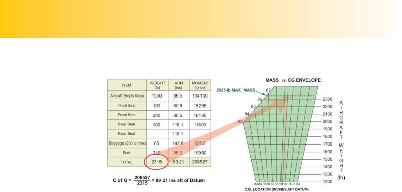
Figure 2.12 Calculation of CG position for a loaded aircraft.
We see that an aircraft is to carry a pilot and two passengers, plus baggage.
The load table contains, in the top line, the information that we already have concerning the aircraft’s mass and CG position, empty. The other lines in the table contain moment arms for the front seats, rear seats, and fuel tanks. The Pilot-in- Command enters the actual mass (weight) values depending on the weight of crew, passengers, lugagge and fuel uptake.
With all figures entered into the table, the pilot completes the moment column for the individual loads, adds up the masses (the payload) and the moment arms and can then calculate the CG position for the loaded aircraft.
He does this by dividing the total of all the moments 206 512 lb-ins by the total mass of the aircraft 2 315 lb, including payload, to get the CG moment arm of 89.21 ins. That is, 89.21 ins aft of the datum. The pilot checks this figure against the permissible CG limits in the MASS - CENTRE OF GRAVITY ENVELOPE and sees that it is, indeed, within the limits stipulated, between 83 ins and 93 ins aft of the datum (See Figure 2.13).
He also sees that the total mass of his loaded aircraft, at 2 315 lb, is within limits (See Figure 2.13).
Both the total mass of the aircraft,
and the position of its Centre of Gravity must be within the limits laid down by the manufacturer.
297
Order: 6026
Customer: Oleg Ostapenko E-mail: ostapenko2002@yahoo.com
Customer: Oleg Ostapenko E-mail: ostapenko2002@yahoo.com
CH AP T ER 2 : CENT R E O F G R AV IT Y CALCU LAT IO NS
Figure 2.13 The loaded aircraft has its mass and CG position within limits.
CALCULATING THE CG POSITION ON LANDING.
Having determined that the aircraft’s mass and CG position are within limits for the proposed flight, a prudent pilot will also check that the CG position will still be within limits for the landing, following the planned fuel consumption.
In order to make this calculation, the pilot needs to calculate the moment about the datum of the fuel that he plans will be consumed during the flight.
We must be very careful in making these calculations, because fuel consumption for American-made aircraft is often given in US gallons per hour, whereas fuel bowsers and pumps in the United Kingdom and Europe deliver fuel in litres. It is vital, therefore, that a pilot should know how to convert between Imperial, American and Metric Units. These conversions can be easily made using your Flight Navigation Computer (See
Volume 3 ‘Navigation and Radio Aids’ and Figure 2.17).
However, to keep matters simple for our CG calculations, we will refer to fuel consumption in mass, using the unit lb. The lb will be quoted in the Pilot’s Operating Handbook for many American aircraft, such as Pipers and Cessnas. Obviously, it is straight forward to convert lb into kg (kilogram).
Let us assume that the pilot calculates that he will use 150 lb of fuel for his planned flight. Given the calculations already made above, will the aircraft’s CG still be within limits on landing?
Well, we know from the load table at Figure 2.12 that the location of the fuel tanks gives the fuel a moment arm of 95 inches. The moment for the fuel planned to be consumed during the flight will, therefore, be:
moment of fuel consumed = 150 lb X 95 ins = 14 250 lb-ins.
In order to calculate the new position of the aircraft’s CG on landing we must do the following:
298