

ppl_06_e2
.pdfID: 3658
Customer: Oleg Ostapenko E-mail: ostapenko2002@yahoo.com
Customer: Oleg Ostapenko E-mail: ostapenko2002@yahoo.com
CH AP T ER 7 : CAR BU R AT IO N Q U
13.An accelerator pump is used to prevent a flat spot. A flat spot arises:
a.When the throttle is opened quickly and the mixture becomes temporarily too rich
b.When the throttle is closed quickly and the engine is starved of fuel
c.When the throttle is closed and the mixture becomes temporarily too rich
d.When the throttle is opened quickly and the mixture becomes temporarily too weak to support combustion
Question |
1 |
2 |
3 |
4 |
5 |
6 |
7 |
8 |
9 |
10 |
11 |
12 |
13 |
|
|
Answer |
|
|
|
|
|
|
|
|
|
|
|
|
|
|
|
T h e |
c o r r e c t a n s w e r s t o t h e s e q u e s t i o n s c a n b e f |
||||||||||||||
b o o |
k . |
|
|
|
|
|
|
|
|
|
|
|
|
|
|
113
Customer: Oleg Ostapenko E-mail: ostapenko2002@yahoo.com
114

Customer: Oleg Ostapenko E-mail: ostapenko2002@yahoo.com
CHAPTER 8
AERO ENGINE FUELS AND FUEL SYSTEMS
115

Order: 6026
Customer: Oleg Ostapenko E-mail: ostapenko2002@yahoo.com
Customer: Oleg Ostapenko E-mail: ostapenko2002@yahoo.com
CH AP T ER 8 : AER O ENG INE F U ELS AND F U EL SY ST EMS
116

ID: 3658
Customer: Oleg Ostapenko E-mail: ostapenko2002@yahoo.com
Customer: Oleg Ostapenko E-mail: ostapenko2002@yahoo.com
CH AP T ER 8 : AER O ENG INE F U ELS AND F U EL
AERO ENGINE FUELS AND FUEL SYSTEMS. |
||
This chapter on Aircraft Engine Fuels |
|
|
and Fuel Systems confines itself to |
|
|
systems and fuels of gasoline (petrol) |
|
|
engines, though brief mention is made |
|
|
of Jet A1 fuel. For technical reasons, |
|
|
the term ‘gasoline’ has been preferred |
|
|
to ‘petrol’, but the reader should note |
|
|
that these two terms are synonymous. |
|
|
Gasoline or petrol, which was originally |
|
|
a by-product of the petroleum industry |
|
|
(kerosene being the main product) |
Figure 8.1 A Fuel Tanker. |
|
became the most common piston |
||
|
||
engine fuel because of its ability to mix |
|
|
readily with air in a carburettor. |
|
|
The fuel used in diesel aero engines, Jet A1 (AVTUR) is given greater mention in |
||
Chapter 3a: Aero Diesel Engines. |
|
|
Cl a s s i f i c a t i o n o f F u e l s b y Sp e c i f i c a t i o n Nu m b e r |
||
Fuel specifications are the means by which producers and users of aviation fuel identify and control the properties necessary for satisfactory performance.
All aviation fuels have a specification number. For instance, Jet A1, the fuel normally used in jet engines, has a specification number DERD
2494. Other jet fuels have different specification numbers.
Gasoline, the fuel used in petrol-driven piston engines, has a specification number (Directorate of Engine Research and Development) DERD 2485. Contained within that blanket specification number are grades of aviation gasoline such as AVGAS 100, AVGAS 100 LL and AVGAS 80.
Q u a l i t y Co n t r o l .
Many tests are carried out on the fuel when it is manufactured. One of those tests is used to determine the fuel’s octane rating. To do this, the particular blend of fuel that is the subject of the test is compared with two reference fuels under standardised conditions in a special test engine (see Figure 8.2.).
The two reference fuels are Iso-octane and Normal Heptane.
117

Order: 6026
Customer: Oleg Ostapenko E-mail: ostapenko2002@yahoo.com
Customer: Oleg Ostapenko E-mail: ostapenko2002@yahoo.com
CH AP T ER 8 : AER O ENG INE F U ELS AND F U EL SY ST EMS
Is o - o c t a n e .
Iso-octane has very good combustion characteristics and shows little tendency to detonate when mixed with air and ignited at high temperatures. It is given an octane rating of 100.
No r m a l H e p t a n e .
Normal heptane on the other hand detonates very readily and has an octane rating of zero.
Co m p a r i n g t h e F u e l o n T e s t. w i t h T w o R e f e
The particular fuel which is to be tested is compared with a blend of the two reference fuels. This is done by first running the test fuel in the special test engine and then trying to produce the same degree of detonation in the engine while using a blend of the two reference fuels.
If the blend of the two reference fuels which gives the same detonation characteristics is say 95% iso-octane and 5% normal heptane, the fuel under test would be given an octane rating of 95. The octane rating is considered to be a measure of how well the fuel resists detonation. So, in other words, the fuel’s octane rating is known as its anti-knock value.
Originally, tests were based on an air/fuel ratio which gave maximum detonation, but a situation which gives maximum detonation is not truly representative of the working range of the engine. Maximum detonation occurs with economical mixtures which are normally used for cruising, but for take-off and climb rich mixtures are used.
P e r f o r m a n c e Nu m b e r .
It is important to know how the fuel will behave under these varying mixture strengths, and so aviation fuel has two ratings. The ‘two rating’ figure is sometimes referred to as the performance number or performance index.
As an example, AVGAS 100 is a 100 octane fuel with a performance number of
100 / 130. The lower figure is the weak mixture detonation point and the higher figure the rich mixture detonation point. It follows that if an engine is designed to use a certain grade of fuel, then a lower grade should never be used, as this would cause detonation. If at any time the correct octane rating is not available, a higher octane rating must be used.
ADDITIVES.
T e t r a e t h y l l e a d .
In the past, in order to increase the octane rating of a fuel, Tetraethyl Lead, or TEL, used to be added. For instance, 2 millilitres of lead were added to each gallon of fuel to take its octane rating to 100 / 130. The action of TEL is to reduce the formation of peroxides which can cause the end gas to explode, but it has to be used with care as, during combustion, lead oxide is formed. Lead oxide is not volatile at these temperatures, and it has a corrosive effect on the exhaust valve, its seat, and the sparking plug electrodes.
Et h y l e n e Di b r o m i d e .
To prevent this corrosion, it is necessary to add ethylene dibromide to the fuel to change the reaction during combustion and to allow lead bromide to form.
118

ID: 3658
Customer: Oleg Ostapenko E-mail: ostapenko2002@yahoo.com
Customer: Oleg Ostapenko E-mail: ostapenko2002@yahoo.com
CH AP T ER 8 : AER O ENG INE F U ELS AND F U EL
Lead bromide is volatile and, thus, is easily ejected with the exhaust gases.
T h e Me d i c a l H a za r d s o f Le a d
Lead in the atmosphere is absorbed into the bloodstream, and can harm the brain. Because of the threat to the health of anyone who breathes in exhaust fumes, fuel companies now use additives other than lead in the fuel to raise its octane rating. Thus we have fuels such as AVGAS 100 LL, the LL standing for low lead.
IDENTIFICATION OF FUELS BY COLOUR.
Figure 8.3 Identifying labels.
To make it easy to identify the fuels, they are coloured differently. For instance, AVGAS 100 LL is coloured blue, while AVGAS 100 is coloured green. AVTUR, which is aviation turbine fuel, is either clear or is of a straw colour.
To assist in differentiating between the fuels when refuelling an aircraft, all refuelling equipment is marked in such a way as to make it easy to identify which fuel may be dispensed from a particular device. The colours of the labels on the equipment and the pipelines are shown here in Figure 8.3.
MO G AS.
Some aviation authorities allow the use of automobile gasoline, or MOGAS, in some aircraft. Within the United Kingdom, the rules governing the use of MOGAS are laid down in Airworthiness Notices, Numbers 98 and 98a. Further information on the use of MOGAS can be found in the CAA Safety Sense Leaflet Number
4a. Great caution should be taken when using MOGAS.
MOGAS has a much higher volatility than AVGAS and, consequently, will evaporate much more quickly. This means that the possibility of vapour locks and carburettor icing occurring is much greater than if AVGAS was being used.
Figure 8.4 Safety Sense Leaflet
Number 4a.
The primary
colour for all labels relating
to 100LL is
red and the colour of the fuel itself should be blue.
Information
regarding aircraft that
may legally
be fuelled with MOGAS may be found in CAA Airworthiness Notices.
119

Order: 6026
Customer: Oleg Ostapenko E-mail: ostapenko2002@yahoo.com
Customer: Oleg Ostapenko E-mail: ostapenko2002@yahoo.com
CH AP T ER 8 : AER O ENG INE F U ELS AND F U EL SY ST EMS
The presence of water in the fuel will cause
fuel system contamination resulting in the loss of engine power.
Fuel In the aircraft tanks
is most likely to be
contaminated by water from atmospheric air in the tanks.
The wing tank
quick-drains should be
used to obtain a sample of the fuel in a suitable container. The sample should be examined for water, and then discarded.
FUEL CONTAMINATION.
The most common contaminant in fuel is water, the presence of which may cause loss of engine power. Water is always present in the fuel in varying amounts despite the manufacturers stringent quality control and preventative measures taken during storage and transfer. However, further measures can be taken to minimise water accretion once the fuel has been transferred to the aircraft tanks. Once the fuel is in the aircraft fuel tanks, the main source of water contamination is atmospheric air which remains within the partially filled tank.
If the tanks are topped-up to full, air, of course, is excluded, together with the moisture it contains, thus minimising the likelihood that the fuel will be contaminated. If the fuel is allowed to settle after replenishment, the water droplets, being heavier than the fuel, will fall to the bottom of the tank and can then be drained off through the water drain valve. If water is allowed to stay in the fuel system, however, it will eventually find its way to the engine where it could cause loss of engine power, or
even a dead cut.
In s p e c t i o n f o r Co n t a m
Each fuel tank is equipped with a drain valve. This is located at the lowest part of the tank, sometimes within a sump which will collect any water as it settles. These wing tank drains should be used first, to drain the sumps. Sufficient fuel should be allowed to flow to ensure removal of contaminants including water. This fuel should be collected in a suitable container, examined for contaminant, and then disposed of in a special container provided by the aerodrome. After having drained any amount of fuel, always ensure that no fire hazard exists before starting the engine. If a large quantity of water is found in the tanks, the aircraft should be declared unserviceable.
i n a t i o n .
Figure 8.5 Fuel Check.
After using each drain, always ensure that it has been closed completely and is not leaking.
Ensure the fuel


 tank vents are not damaged or blocked up, otherwise it will
be difficult getting fuel to the engine from that tank.
F u e l T a n k V e n t s .
While checking the fuel tank drains, the pilot should also check the fuel tank vents (see Figure 8.6). Each tank is fitted with a forward facing vent pipe which allows atmospheric pressure to be maintained inside. They are usually
fitted in the lower surface of the wing.
Make sure that the fuel vents are not damaged or that they are not blocked up in any way; otherwise a depression will form in the tank which will adversely
affect fuel flow to the engine.
Figure 8.6 Fuel Tank Vent.
120

ID: 3658
Customer: Oleg Ostapenko E-mail: ostapenko2002@yahoo.com
Customer: Oleg Ostapenko E-mail: ostapenko2002@yahoo.com
CH AP T ER 8 : AER O ENG INE F U ELS AND F U EL
F u e l St r a i n e r .
The fuel strainer (see Figure 8.7) is also equipped with a quick-drain facility. The fuel strainer itself is located at the lowest point of the fuel system, usually somewhere in the engine compartment. The fuel strainer should be drained once for each of the tanks which can be selected on the aircraft’s fuel selector valve. Once again, sufficient fuel should be allowed to flow to ensure complete removal of any water.
THE FUEL SYSTEM.
Figure 8.7 Fuel Strainer.
A simple light aircraft fuel system is shown in Figure 8.8. The fuel is contained in two wing tanks, each of which has a quick-drain fitted at its lowest point.
Figure 8.8 A Simple Fuel System.
Fuel quantity is measured by simple float-type sensors in the tanks and is indicated to the pilot in the cockpit on fuel guages. Float-type sensors are fairly unreliable, except when the aircraft is on the ground or in prolonged straight and level flight. So, before flight, a pilot must always visually check the fuel contents, by removing the tank filler caps and looking into the tanks to make his own assessment of the quantity.
The fuel passes to the engine system via a tank selector valve. This allows the pilot to control fuel flow from each tank in turn and, thus, keep the aircraft balanced laterally.
Float-type sensors are fairly
unreliable, except on the ground or in prolonged straight and level flight. So before flight always visually check the contents of the fuel tanks.
121
Order: 6026
Customer: Oleg Ostapenko E-mail: ostapenko2002@yahoo.com
Customer: Oleg Ostapenko E-mail: ostapenko2002@yahoo.com
CH AP T ER 8 : AER O ENG INE F U ELS AND F U EL SY ST EMS
|
|
|
Next in line is the fuel strainer, at the lowest point in the system. Remember, during |
|
|
In most light |
|
|
|
the pre-flight check the fuel strainer should be drained twice via its drain, with each |
|
|
|
aircraft the |
|
|
|
tank selected in turn. |
|
|
|
electrical fuel |
|
pump should be switched |
Me c h a n i c a l a n d El e c t r i c a l P u m p s . |
||
on for take-off, flight below |
|||
1,000 feet, landing and when |
After the fuel strainer comes the electrical fuel pump. It is sometimes called the |
||
changing over the fuel tank |
booster pump, or the auxiliary pump. It is fitted to the system in case of failure of the |
||
selector. |
mechanical fuel pump. Some fuel systems have their fuel pumps in parallel. |
||
|
|
|
|
|
|
The normal |
|
|
|
location of an |
|
|
|
|
|
|
|
electrically |
|
|
|
driven |
|
auxiliary fuel pump on a piston |
|
||
engine is upstream of the |
|
||
engine-driven pump. |
|
||
|
|
|
|
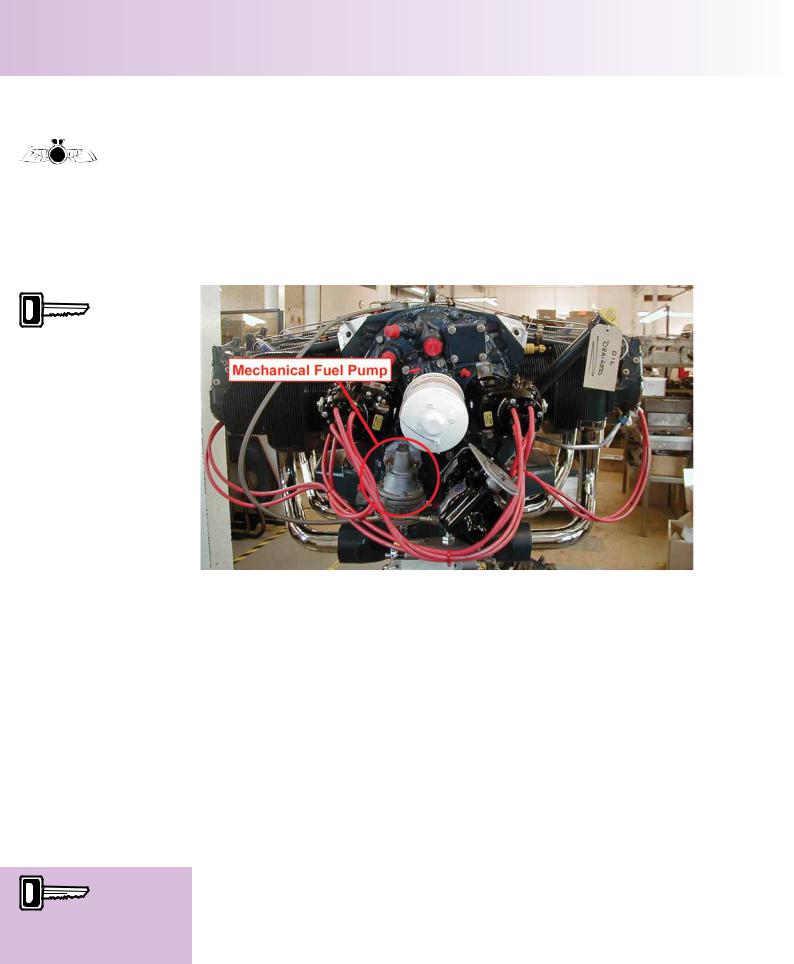
Figure 8.9 Mechanical Fuel Pump.
The Pilot’s Operating Handbook for most light aircraft advises that the electrical fuel pump should be switched on for take-off, flight below 1 000 feet, and for landing. It is also advisable to select this pump to ‘on’ when using the tank selector valve to change tanks.
A fuel pressure gauge may be included in the system (see Figure 8.8.) This can be used to check the output of the electrical pump when the engine is not running.
Downstream of the electrical pump is the engine-driven mechanical pump (see Figure 8.9). The fuel pressure gauge will sense the output pressure of the mechanical pump whenever the electrical pump is switched off.
High wing aircraft, with tanks in the wings only, may not require a fuel pump, relying on gravity as the prime mover of the fuel to the engine system.
Priming pump fuel
is normally delivered
directly to the induction manifold or inlet valve port.
Ca r b u r e t t o r a n d P r i m i n g P u m p .
The final item in the system is the carburettor. This meters the fuel to the engine in response to the pilot’s operation of the authority of the throttle and the mixture control.
The priming pump is a hand operated device which is used to pump fuel to the inlet valve ports of the cylinders prior to engine start. The priming pump takes its fuel from the top of the fuel strainer (see Figure 8.8).
122