

Measurement and Control Basics 3rd Edition (complete book)
.pdfChapter 5 – Pressure Measurement |
135 |
Piezoelectric-type Sensor
A certain class of crystals, called piezoelectric, produce an electrical signal when they are mechanically deformed. The voltage level of the signal is proportional to the amount of deformation. Normally, the crystal is mechanically attached to a metal diaphragm. One side of the diaphragm is connected to the process fluid to sense pressure, and a mechanical linkage connects the diaphragm to the crystal.
The output voltage signal from the crystal is very small (normally in the microvolt range), so you must use a high-input impedance amplifier. The amplifier must be mounted within a few feet of the sensor to prevent signal loss. The crystals can tolerate temperatures up to 400°F, but they are affected by varying temperatures and must be temperature compensated.
Capacitance-type Sensor
Another example of an electronic unit connected to a pressure diaphragm is the variable capacitor pressure-sensing cell. A capacitor consists of two metal plates or conductors that are separated by an insulating material called a dielectric. In a capacitance-type pressure sensor, a differential pressure is applied to a diaphragm. This in turn causes a filling fluid to move between the isolating diaphragm and a sensing diaphragm. As a result, the sensing diaphragm moves toward one of the capacitor plates and away from the other, thus changing the capacitance of the device. Since capacitance is directly proportional to the distance between the plates, the pressure that is applied to the cell can be directly related to the change in capacitance. A pair of electrical leads is connected to an electronic circuit that measures the change in capacitance. This capacitance change is then converted into an electronic signal in the transmitter, which is calibrated in pressure units.
There are two common electrical methods for detecting the capacitance change. In one method, the change is detected by measuring the magnitude of an AC voltage across the plates when they are excited. In the other method, the sensing capacitor forms part of an oscillator, and the electronic circuit changes the frequency to tune the oscillator. These changes in frequency are then electronically converted into a pressure change.
Variable Inductance Sensor
Figure 5-11 shows another example of an electrical sensor used with a pressure-sensing diaphragm. Inductance, a fundamental property of electromagnetic circuits, is the ability of a conductor to produce induced voltage when the current in the circuit varies. A long wire has more

136 Measurement and Control Basics
P1 
 Magnetic Cores
P2
Sensing Coils
Diaphragm
Figure 5-11. Variable inductance pressure sensor
inductance than a short wire since more conductor length is cut by magnetic flux, producing more induced voltage. Similarly, a coil of wire has more inductance than the equivalent length of straight wire because the coil concentrates magnetic flux. The core material around which the coil is wound also affects the inductance.
In other words, the inductance of a coil of wire or inductor depends on the number of turns and the magnetic properties of the material around the wire. The variable inductance device shown in Figure 5-11 uses two coils magnetically coupled through a core. The core changes properties as the applied pressure moves the diaphragm. The inductance is measured using a variety of electronic circuits. For example, you may use the pressuresensing variable inductor as a component in an oscillator circuit.
Strain Gauge Pressure Sensors
The deformation of a material is called strain, and the mechanical force that produces the deformation is called stress. Strain is a unitless quantity, but it is common practice to express it as the ratio of two length units, such as in./in. or m/m.
A strain gauge is a device that changes resistance when stretched. A typical unbounded strain gauge is shown in Figure 5-12. It consists of multiple runs of very fine wire that are mounted to a stationary frame on one end and a movable armature on the other. The movable armature is generally connected to a pressure-sensing bellows or to a diaphragm. The multiple runs of wire amplify small movements along the direction of the wire. Very small pressure changes can be detected if there are a large number of wire runs.

Chapter 5 – Pressure Measurement |
137 |
Wire Elements
Stationary
Frame
Movable
Armature
Figure 5-12. Unbonded strain gauge
In Chapter 3, we saw that the resistance of a metal wire is given by the following equation:
|
Ro = r |
lo |
|
(5-16) |
|
A0 |
|||
|
|
|
||
where |
|
|
|
|
Ro |
= the original wire resistance (Ω |
) |
||
r |
= the resistivity of the wire in (Ω |
-m) |
||
lo |
= the wire length (m) |
|
||
Ao |
= the starting cross-sectional area (m2) |
|||
Suppose the wire is stretched. Then, we know that the wire will elongate by some amount ∆ l, so the new length is now l = lo + ∆ l. It is also true that under this stress/strain condition, though the wire lengthens, its volume
will remain constant. Because the volume unstretched is V = lo Ao, it fol- |
|
lows that the cross-sectional area must decrease by some area |
∆ A, so the |
volume (V) does not change. The new area will be Ao - ∆ A. Therefore, |
|
V = lo Ao = (lo + ∆ l)(Ao - ∆ A) |
(5-17) |
Now, because both the length and the area have changed, the resistance of the wire will also change to
R = r |
lo |
+ ∆ l |
(5-18) |
|
A0 |
− ∆ A |
|||
|
|

138 Measurement and Control Basics
Using Equations 5-17 and 5-18, the new resistance is given approximately by the following:
|
|
l |
|
|
∆ l |
|
||||
R ≈ |
r |
o |
1+ 2 |
|
|
|
|
(5-19) |
||
|
|
|
||||||||
|
|
A0 |
|
|
lo |
|
||||
From this equation, we can obtain the resistance change as |
|
|||||||||
∆ |
R≈ |
2 R |
∆ |
l |
|
(5-20) |
||||
lo |
||||||||||
|
|
|
|
|
||||||
Equation 5-20 is the basic equation that underlies the operation of wire strain gauges because it shows that the strain (∆ l/lo) converts directly into a resistance change. Example 5-9 illustrates this concept.
EXAMPLE 5-9
Problem: Find the change in wire resistance for a strain gauge that has a nominal wire resistance of 100Ω , when it is subjected to a strain of
1000 µ m/m.
Solution: The change in strain gauge resistance can be found by using Equation 5-19:
∆ R≈ 2R ∆ l lo
∆ R = 2(100Ω )(1000 x 10–6) = 0.2Ω
Example 5-9 points out that in strain gauges the change in resistance is very small. This means that when using a strain gauge sensitive electronic circuits must be used to obtain an accurate pressure measurement.
It is important to note that the signal produced by most electronic pres- sure-sensing elements cannot be sent more than a few feet. Therefore, most electronic pressure devices have a transmitter mounted on the sensor. The transmitter converts the measured signal into a 4-to-20-mA current signal, which is sent to a local indicator or to a central control area for indication, control, or recording.

Chapter 5 – Pressure Measurement |
139 |
Pressure Transmitter Applications
The most common application for a pressure transmitter is measuring liquid level in a process tank, as shown in Figure 5-13. Pressure transmitters determine level by using the principle that pressure is proportional to the height of the liquid multiplied by its specific gravity (SG). The pressure generated by the liquid is directly related to its height, and this pressure is independent of volume and the shape of the tank. Thus, 100 inches of water will produce 100 inH2O of pressure since water has a specific gravity of one. If the specific gravity is different, the pressure changes proportionately. For example, if the specific gravity is 0.95, a liquid level of 100 inches produces a pressure of 95 inH2O. If the specific gravity is 1.1, then a level of 100 inches produces 110 inH2O of pressure.
|
Top Instrument Tap |
Atm. |
|
Lmax = 100” |
|
SG = 0.95 |
dP Transmitter |
|
4 to 20 maDC |
Lmin = 0” |
Atm. |
Hi |
Lo |
Figure 5-13. Open tank, dP cell horizontal to tap |
|
Both gauge and differential pressure (dP) transmitters can be used to measure level. Gauge pressure transmitters are simply dP transmitters or cells that have their low-pressure port connected to the atmosphere. Either type of instrument is appropriate for use on an open tank or on a tank vented to the atmosphere, as shown in Figure 5-13. If the pressure inside a tank is either positive or negative, you must use a dP cell. In this case, you would connect the low-pressure port to the pressure above the fluid.
In the open-tank application shown in Figure 5-13, the pressure transmitter measures the pressure between the minimum fluid level (Lmin) at the instrument tap and the maximum fluid level (Lmax) in the tank using the high (Hi) pressure port on the pressure cell. The low (Lo) pressure side of the cell senses only the atmospheric pressure. Since atmospheric pressure is sensed by both sides of the dP cell, its effect is cancelled.
140 Measurement and Control Basics
The transmitter output is a 4-to-20-milliamp (mA) current signal that represents the fluid level in the tank. The span points for the dP cell are calculated as follows:
4mA = Lminx SG
=0 inches x 0.95
= 0 inH2O
20mA = Lmaxx SG
=100 inches x 0.95
=95.0 inH2O.
So the span of the transmitter is given by the following:
Span = (Lmax - Lmin) x SG
=(95.0 – 0) inH2O
=95.0 inH2O.
The 4-to-20-maDC current output signal from the dP transmitter is calibrated from 0 to 95 inH2O.
In the next application, shown in Figure 5-14, the pressure transmitter is mounted 20 inches below the bottom instrument tap on the process tank. To calculate the 4 mA point for the transmitter, we need to consider the pressure that is developed by the process fluid in the extra 20 inches of distance, d. In this case, the span points for the dP cell are calculated as follows:
4 mA = (Lmin+d) x SG
=(0 + 20) inches x 0.95
=19 inH2O
20mA = (Lmin+d) x SG
=(100+ 20) x SG
=120 inches x 0.95
=114 inH2O.
So, the dP transmitter must be calibrated from 19 inH2O to 114 inH2O.
In the next application, shown in Figure 5-15, the tank is closed, and there is a “Dry Leg” between the top instrument tap and the low-pressure (LP)

Chapter 5 – Pressure Measurement |
141 |
Lmax = 100”
SG = 0.95 


 4 to 20 maDC
Lmin = 0” 


d
Hi Lo
Figure 5-14. Open tank – dP cell below bottom tap
side the dP cell. A “Dry Leg” is defined as the length of instrument piping between the process and a pressure transmitter that is filled with air or another noncondensing gas.
Static Pressure |
|
Lmax = 100” |
|
SG = 0.95 |
|
Hi |
Lo |
Lmin = 0” |
|
dP Cell
Figure 5-15. Closed tank with dry leg and horizontal dP cell
In the application shown in Figure 5-15, the high-pressure (HP) port senses the liquid level and the pressure above it. The low-pressure (LP) port senses only the pressure above the liquid. The impact of the static pressure in the closed tank is eliminated by using the differential pressure transmitter. The dP transmitter output is a 4-to-20-milliamp (mA) current signal that represents the fluid level in the tank.
142 Measurement and Control Basics
The span points for the dP cell are calculated as follows:
4mA = Lminx SG
=0 inches x 0.95
= 0 inH2O
20mA = Lmaxx SG
=100 inches x 0.95
=95.0 inH2O.
So, the differential pressure transmitter is calibrated for 0 to 95.0 inH2O.
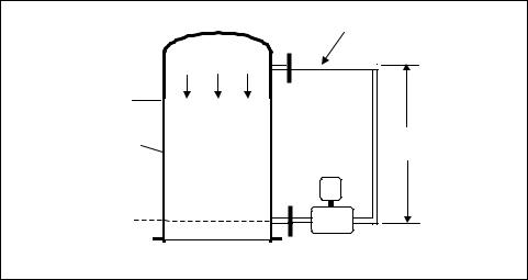
In the next application, shown in Figure 5-16, the tank is closed, and there is a “Wet Leg” between the top instrument tap and the low-pressure (LP) side the dP cell. A “Wet Leg” is defined as the length of instrument piping between the process and a pressure transmitter that is filled with a compatible fluid and kept at a constant height.
|
Wet Leg, SGw = 1.2 |
Static Pressure |
|
Lmax = 100” |
|
SG = 0.95 |
h = 120” |
|
|
Hi |
Lo |
Lmin = 0” |
|
|
dP Cell |
Figure 5-16. Closed tank with wet leg and horizontal dP cell
Since the reference leg is wet or filled, you must make a correction for the weight of the fluid in the wet leg. The specific gravity of the wet leg is 1.2 for the application shown in Figure 5-16. The fluid in the wet leg should be heavier than the process liquid. It is also important to maintain a constant height for the fill fluid in the wet leg.

Chapter 5 – Pressure Measurement |
143 |
The span points for the dP cell are calculated as follows:
4mA = (Lminx SG) – (h x SGw)
=(0” x 0.95) – (120” x 1.2)
= -144 inH2O
20mA = (Lmaxx SG) – (h x SGw)
=(100 inches x 0.95) – (120” x 1.2)
=(95.0 – 144) inH2O.
=-49 inH2O.
So, the calibrated span for the dP transmitter is –144 to –49 inH2O.
The final pressure transmitter application we will discuss is shown in Figure 5-17. It is a closed tank that has a wet leg and a dP transmitter below the bottom instrument tap. The dP cell is used to compensate for the static pressure in the process tank.
Wet Leg, SGw = 1.2
Static Pressure
Lmax = 100”
SG = 0.95 |
h = 120” |
|
Lmin = 0” |
|
|
d = 20” |
Hi |
Lo |
|
dP Cell |
Figure 5-17. Closed tank with wet leg and dP cell below tap
Since the reference leg is wet or filled, you must make a correction for the weight of the fluid in the wet leg. We also need to correct for the fact that dP cell is mounted 20 inches below the bottom instrument tap.
144 Measurement and Control Basics
The span calibration points for the differential pressure instrument in Figure 5-17 are calculated as follows:
4 mA = (Lmin+ d) SG – hx SGw
=(0” + 20) x 0.95 – (120” x 1.2)
=(19 – 144) inH2O
=–125 inH2O
20 mA = (Lmax+ d) x SG – (h x SGw)
=(100” + 20”) x 0.95 – (120” x 1.2)
=(114 – 144) inH2O.
=–30 inH2O.
So, the calibrated span of the dP transmitter is –125 to –30 inH2O.
In standard mount or dry leg applications, the accuracy of the level measurement is directly related to the accuracy of the pressure transmitter. However, the dry leg must be dry: any condensation in the leg will create an error in the level measurement. You prevent condensation in most cases by doing heat tracing of the reference leg. However, if condensation is a significant problem, it may be better to use a wet leg installation.
With a wet leg installation, any change in the height or density of the wet leg fluid influences the accuracy of the level measurement. It is important to maintain the height of the wet leg fluid constant. If the height of the wet leg changes, it will result in a reference point shift. A large change in ambient temperature will cause a change in the density of the fill fluid. This in turn will change both the zero (4 mA) and maximum (20 mA) calibration points on the transmitter. If both the height and density of the fill fluid change, the measurement problems are compounded.
EXERCISES
5.1Find force F2, given the following data on the hydraulic press shown in Figure 5-3: A1=1.0 in.2, A2=10 in.2, and F1=25 lb.
5.2A gas sample occupies a volume of 5 ft3 at a pressure of 20 psia and a temperature of 70°F. What will be its volume if the pressure increases to 30 psia and the temperature remains at 70°F?