

Measurement and Control Basics 3rd Edition (complete book)
.pdfChapter 4 – Digital System Fundamentals |
105 |
ASCII Code
The most widely used code is ASCII, the American Standard Code for Information Interchange. Developed in 1963, this code has seven bits for data (allowing 128 characters), as Table 4-6 shows.
The ASCII code can operate synchronously or asynchronously with one or two stop bits. ASCII format has thirty-two control characters, the legend for which is given in Table 4-7. These control codes are used to indicate, modify, or stop a control function in the transmitter or receiver. Seven of the ASCII control codes are called format effectors because they pertain to the control of a printing device. Format effectors increase code efficiency and speed because they replace frequently used character combinations with a single code. The format effectors used in the ASCII code are BS (backspace), HT (horizontal tab), LF (line feed), VT (vertical tab), FF (form feed), CR (carriage return), and SP (space).
Table 4-6. ASCII Code
Bits |
7 |
0 |
0 |
0 |
0 |
1 |
1 |
1 |
1 |
|
6 |
0 |
0 |
1 |
1 |
0 |
0 |
1 |
1 |
|
5 |
0 |
1 |
0 |
1 |
0 |
1 |
0 |
1 |
|
|
|
|
|
|
|
|
|
|
4321 |
HEX |
0 |
1 |
2 |
3 |
4 |
5 |
6 |
7 |
0000 |
0 |
NUL |
DLE |
SP |
0 |
@ |
P |
‘ |
p |
0001 |
1 |
SOH |
DC1 |
! |
1 |
A |
Q |
a |
q |
0010 |
2 |
STX |
DC2 |
“ |
2 |
B |
R |
b |
r |
0011 |
3 |
ETX |
DC3 |
# |
3 |
C |
S |
c |
s |
0100 |
4 |
EOT |
DC4 |
$ |
4 |
D |
T |
d |
t |
0101 |
5 |
ENQ |
NAK |
% |
5 |
E |
U |
e |
u |
0110 |
6 |
ACK |
SYN |
& |
6 |
F |
V |
f |
v |
0111 |
7 |
BEL |
ETB |
’ |
7 |
G |
W |
g |
w |
1000 |
8 |
BS |
CAN |
( |
8 |
H |
X |
h |
x |
1001 |
9 |
HT |
EM |
) |
9 |
I |
Y |
i |
y |
1010 |
A |
LF |
SUB |
* |
: |
J |
Z |
j |
z |
1011 |
B |
VT |
ESC |
+ |
; |
K |
[ |
k |
{ |
1100 |
C |
FF |
FS |
’ |
< |
L |
\ |
l |
| |
1101 |
D |
CR |
GS |
- |
= |
M |
] |
m |
} |
1110 |
E |
SO |
RS |
. |
> |
N |
^ |
n |
~ |
1111 |
F |
SI |
US |
/ |
? |
O |
- |
o |
DEL |
|
|
|
|
|
|
|
|
|
|

106Measurement and Control Basics
Table 4-7. Legend for ASCII Control Characters
Mnemonic |
Meaning |
Mnemonic |
Meaning |
|
|
|
|
NUL |
Null |
DLE |
Data Link Escape |
SOH |
Start of heading |
DC1 |
Device Control 1 |
STX |
State of Text |
DC2 |
Device Control 2 |
ETX |
End of Text |
DC3 |
Device Control 3 |
EOT |
End of Transmission |
DC4 |
Device Control 4 |
ENQ |
Enquiry |
NAK |
Negative Acknowledge |
ACK |
Acknowledge |
SYN |
Synchronous Idle |
BEL |
Bell |
ETB |
End of Transmission Block |
BS |
Backspace |
CAN |
Cancel |
HT |
Horizontal Tabulation |
EM |
End of Medium |
LF |
Line Feed |
SUB |
Substitute |
VT |
Vertical Tabulation |
ESC |
Escape |
FF |
Form Feed |
FS |
File Separator |
CR |
Carriage Return |
GS |
Group Separator |
SO |
Shift Out |
RS |
Record Separator |
SI |
Shift In |
US |
Unit Separator |
|
|
DEL |
Delete |
|
|
|
|
Example 4-7 shows how to express a simple message in ASCII code.
EXAMPLE 4-7
Problem: Express the words PUMP 100 ON using ASCII code. Use hex notation for brevity.
Solution: Using Table 4-6, we obtain the following:
MESSAGE: |
PUMP 100 0N |
ASCII (Hex) String: |
50 55 4D 50 20 31 30 30 20 4F 4E |
Binary Logic Functions
In control system applications, the binary numbers one (1) and zero (0) are represented by voltage levels, relay contact status, switch position, and so on. For example, in transistor-transistor logic (TTL) gates, a binary one is represented by a voltage signal in the range of 2.4 to 5.0 volts, and a binary zero is represented by a voltage level between 0 and 0.8 volt. Solid-state

Chapter 4 – Digital System Fundamentals |
107 |
electronic circuits are available that manipulate digital signals so they perform a variety of logical functions, such as NOT, AND, OR, NAND, and NOR. In hardwired electrical logic systems, electrical relays are used to implement the logic functions.
NOT Function
The most basic binary logic function is the NOT or inversion function. The NOT, or logic inverter as it is also known, produces an output that is opposite to that of the input. An inversion bar is drawn over a logic variable to indicate the NOT function. For example, if a NOT operation is performed on a logic variable A, it is designated by Z = A .
Table 4-8 shows a binary logic truth table for the NOT function in which are listed the results of the NOT function on the Input A. In relay-based logic circuits, a normally closed (NC) set of contracts is used to perform the NOT function, as shown in Figure 4-2. If the electric relay A is not energized, there is electrical current flow or logic continuity through the normally closed contacts, so output relay coil is energized or On. In other words, if input A is logic 0 or not On then the output Z is logic 1 or On. If input A is logic 1 or On, the normally closed contacts are opened, there is no current flow or logic flow in the circuit, relay Z is off, and output Z is 0.
Table 4-8. NOT function Binary Logic Truth Table
Input |
Output |
|
|
A |
Z |
0 |
1 |
1 |
0 |
|
|
Normally Closed (NC) |
Control Relay |
A |
Z |
|
Figure 4-2. NOT function implemented with relay
OR Function
A logical OR function that has two or more inputs and a single output operates in accordance with the following definition: The output of an OR function assumes the 1 state if one or more inputs assume the 1 state.

108 Measurement and Control Basics
The inputs to a logic function OR gate can be designated by A, B, …, N and the output by Z. We make the assumption that the inputs and outputs can take only one of two possible values, either 0 or 1. The logic expression for this function is Z = A + B + … + N. Table 4-9 gives a two-input truth table for a two-input OR function.
Table 4-9. Two-input OR Function Truth Table
Input |
Output |
|
|
|
|
A |
B |
Z |
0 |
0 |
0 |
0 |
1 |
1 |
1 |
0 |
1 |
1 |
1 |
1 |
|
|
|
Here is an example of OR logic in process control: If the water level in a hot water heater is low, or the temperature in the tank is too high, a logic system can be designed that will turn off the heater in the system using logic circuits or relays. Figure 4-3 shows this application, which uses relays to perform the logic function.
|
Heater |
Water Level Low |
Control Relay |
A |
Z |
|
|
Water Temp. High |
|
B
Figure 4-3. Relay-based OR logic application
You can easily verify the following logic identities for OR functions by using the two-input truth table for the OR function given in Table 4-9:
A + B + C = (A + B) + C = A + (B + C) |
(4-5) |
A + B = B + A |
(4-6) |
A + A = A |
(4-7) |
A + 1 = 1 |
(4-8) |
A + 0 = A |
(4-9) |
Chapter 4 – Digital System Fundamentals |
109 |
Remember that A, B, and C can only assume the value of 0 or 1.
AND Function
An AND function has two or more inputs and a single output, and it operates according to the following rule: The output of an AND gate assumes the 1 state if and only if all the inputs assume the 1 state. The general equation for the AND function is given by ABC ..... N = Z. Table 4-10 is a two-input AND function truth table.
Table 4-10. Two-input AND Truth Table
Inputs |
Output |
|
|
|
|
A |
B |
Z |
0 |
0 |
0 |
0 |
1 |
0 |
1 |
0 |
0 |
1 |
1 |
1 |
|
|
|
Consider the following example of AND logic being used in process control. Suppose the liquid level in a process tank is high and the inlet feed pump to the tank is running. Design a logic circuit for opening the tank outlet valve using electric relays. Figure 4-4 shows the relay ladder logic diagram that will perform the required AND function for this example.
Tank Level High |
Pump Running |
Open Outlet Valve |
A |
B |
Z |
|
|
|
|
||
Figure 4-4. Relay-based AND logic control application |
||
The logic expressions for the AND function are as follows: |
||
ABC = (AB)C = A(BC) |
(4-10) |
|
|
AB = BA |
(4-11) |
|
AA = A |
(4-12) |
|
A1 = A |
(4-13) |
|
A0 = 0 |
(4-14) |
110 Measurement and Control Basics
You can verify these identities by referring to the definitions of the AND gate and by using a truth table for the AND gate. For example, you can verify Equation 4-13 (A1 = A) as follows: let B = 1 and tabulate AB = Z or A1 = Z in a truth table such as the following:
Inputs |
Output |
|
|
|
|
A |
B |
Z |
0 |
1 |
0 |
1 |
1 |
1 |
|
|
|
Note that A = Z in this truth table, so A1 = A for both values (0 or 1) of A.
Some important auxiliary identities used in logic design are as follows:
|
A + AB |
(4-15) |
|
A + |
|
|
(4-16) |
AB = A + B |
|||
(A + B)(A + B) = A + BC |
(4-17) |
||
These identities are important because they help reduce the number of logic elements or gates that are required to implement a logic function.
NOR Function
Another common logic gate is the NOR gate. Table 4-11 shows its operation for two inputs. It produces a logic 1 result if and only if all inputs are logic 0. Notice that the output of the NOR function is the opposite of the output of an OR gate.
Table 4-11. Two-input NOR Truth Table
Inputs |
Output |
|
|
|
|
A |
B |
Z |
0 |
0 |
1 |
0 |
1 |
0 |
1 |
0 |
0 |
1 |
1 |
0 |
|
|
|
NAND Function
Another logic operation that is relevant to process control is the NAND gate. Table 4-12 summarizes its operation for a two-input NAND function.
Chapter 4 – Digital System Fundamentals |
111 |
Note that the output of the NAND function is the exact opposite of the AND function’s output. When both inputs to the NAND are 1, the output is 0. In all other configurations, the NAND function output is 1.
Table 4-12. Two-input NAND Function Truth Table
Inputs |
Output |
|
|
A B |
Z |
0 0 |
1 |
0 1 |
1 |
1 0 |
1 |
1 1 |
0 |
|
|
Logic Function Symbols
Two common sets of symbols are used in process control applications to represent logic function: graphic and ladder. The graphic symbols are generally used on engineering drawings to convey the overall logic plan for a discrete or batch control system. They are based on the standard ANSI/ ISA-5.2-1976 (R1992) - Binary Logic Diagrams for Process Control. The ladder logic symbols are used to describe a logic control plan if relays are being used to implement the control system or if programmable controller ladder logic is used to implement the control plan. Figure 4-5 compares these two sets of symbols for the most common logic functions encountered in logic control design.
Ladder Logic Diagrams
Ladder diagrams are a traditional method for describing electrical logic controls. These circuits are called ladder diagrams because they look like ladders with rungs. Each rung of a ladder diagram is numbered so we can easily cross-reference between the sections on the drawing that describe the control.
The utility of ladder logic diagrams can best be appreciated by investigating a simple control example. Figure 4-6 shows a typical process-level control application. In this application, let us assume that the flow into the tank is random. Let us also assume that we need to control the level in the tank by opening or closing the outlet valve (LV-1) based on the tank’s level as it is sensed by a level switch (LSH-1). We will also provide the operator with a three-position switch so he or she can maintain the proper level in the tank by manually turning the valve on or off or by selecting automatic control position. The hand switch (HS-1) is designated “HOA,” where “H”

112 Measurement and Control Basics
Logic |
|
Logic |
Ladder |
|
Function |
|
Symbol |
Symbol |
|
|
|
|
A |
Z |
|
|
|
|
|
NOT, Z = A |
A |
|
Z = A |
|
|
|
|
A |
Z |
|
|
|
|
|
OR, Z =A + B |
A |
OR |
Z |
|
B |
|
|||
|
|
B |
|
|
|
A |
|
A B |
Z |
AND, Z = A B |
A |
Z |
|
|
B |
|
|||
|
|
|
|
|
Figure 4-5. Comparison of logic symbols |
|
|||
Feed In
|
LSH |
|
Process |
1 |
|
HOA |
||
Tank |
||
HS |
||
|
||
|
1 |
LV 1
S
 Feed Out
Figure 4-6. On/off control of process tank level
represents hand or manual position, the letter “O” is for the off position, and the “A” represents the automatic operation of the solenoid valve based on some control logic.
The ladder logic design for this application is shown in Figure 4-7. If the panel-mounted HOA switch is in the automatic position and the level switch is closed, the solenoid will be energized. This is a simple example

Chapter 4 – Digital System Fundamentals |
113 |
of a logical AND function in process control. If the HOA switch is in the hand or manual position, the valve will also be turned on.
Hand |
Off |
|
Auto |
|
|
|
|
LV-1 |
|
X00 |
|
|
00X |
LSH-1 |
|
|
|
|
HS-1 |
|
|
(HOA) |
|
Figure 4-7. Ladder diagram for process tank level control
Suppose that we designate the logic variables for the ladder diagram shown in Figure 4-7 as follows: A for hand position of HOA switch, B for automatic position of the HOA switch, C for the status of level switch LSH-1, and Z for the output to turn on solenoid valve LV-1. In this case, the logic equation for the control circuit is Z = A + BC. We can implement this control circuit with logic gates, as shown in Figure 4-8.
(Level Switch) C
AND
(Automatic Position) B
(Hand Position) A |
OR |
Z (Solenoid Valve) |
|
|
Figure 4-8. Logic gate implementation of tank level control
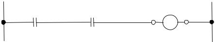
A more complex application might be to control the liquid level of the tank between two level switches: a level switch high (LSH) and a level switch low (LSL). In this application, a pump supplying liquid to a tank is turned on and off to maintain the liquid level in the tank between the two level switches. The process, shown in Figure 4-9, uses a regulated flow of steam to boil down a liquid so as to produce a more concentrated solution. This solution is drained off periodically by opening a manual valve on the bottom of the tank. Note that a small diamond symbol is used to indicate that the pump is interlocked with the level switches on the tank.

114 Measurement and Control Basics
|
|
|
Vapor Out |
|
|
LSH |
Steam |
|
|
1 |
|
|
|
|
Out |
Start |
Stop |
|
Condenser |
HS |
HS |
|
|
|
|
||
1 |
2 |
|
Steam |
|
|
|
|
|
|
|
In |
|
I |
LSL |
|
|
Interlock |
1 |
|
|
|
|
|
|
Symbol |
|
|
|
|
|
Drain |
Feed In |
|
Valve |
|
|
|
||
|
Feed Pump |
|
|
Figure 4-9. Pump control of condenser liquid level
Figure 4-10 shows the electrical ladder diagram that is used to control the feed pump and hence the liquid level in the process tank. To explain the logic of the control system, we will assume that the tank is empty and the low-level and high-level switches are closed. When a level switch is activated, the normally open contacts are closed and the normally closed contacts are opened. To start the control system, the operator depresses the start push button (HS-1). This energizes control relay CR1, which seals in the start push button with the first set of contacts, denoted as CR1(1) on the ladder diagram. At the same time, the second control relay (CR2) is energized in rung 3 through contacts on LSH-1, LSL-1, and CR1. This turns on the pump motor starter MS-1. The first set of contacts on CR2(1) is used to seal in the low-level switch contacts. As a result, when the level in the tank rises above the position of the low-level switch on the tank, the pump will stay on until the liquid level reaches the high-level switch. After the high-level switch is activated, the pump will be turned off. The system will now cycle on and off between the high and low levels until the operator depresses the stop push button (HS-2).
This pump control application is a typical example of logic control in the process industries. Plants can implement the logic control system by using a hardwired relay-based logic system, a programmable logic controller, or a distributed control system.