

Measurement and Control Basics 3rd Edition (complete book)
.pdfChapter 6 – Level Measurement and Control |
155 |
Atm. |
LT |
LI |
Atm. |
LT |
LI |
|
101 |
101 |
102 |
102 |
|||
|
||||||
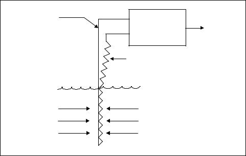
Figure 6-8. DIaphragm box level measurement |
|
|
||||
presents two versions of continuous level detection. The diaphragm box instrument shown on the right side of the figure isolates the captive air from the process fluid. The unit consists of an air-filled diaphragm that is connected to a pressure detector via air tubing. As the level rises above the diaphragm, the liquid head pressure compresses the captive air inside. A differential pressure element senses the air pressure, which is displayed as level.
The instrument shown on the left side of Figure 6-8 is submerged in the vessel. The static head of the liquid exerts an upward pressure on the diaphragm, which increases as the level rises.
Electrical-type Instruments
A wide variety of instruments and sensors use basic electrical principles to measure and detect level. The three common electrical-type levelmeasuring devices we will discuss here are capacitance probes, resistance tapes, and conductivity probes.
Capacitance Probes
A capacitor consists of two conductors separated by an insulator. The conductors are called plates, and the insulator is referred to as the dielectric. The basic nature of a capacitor is its ability to accept and store an electric charge. When a capacitor is connected to a battery, electrons will flow from the negative terminal of the battery to the capacitor, and the electrons on the opposite plate of the capacitor will flow to the positive terminal of the
156 Measurement and Control Basics
battery. This electron flow will continue until the voltage across the capacitor equals the applied voltage.
Capacitor size is measured in farads. A capacitor has the capacitance of one farad (1 F) if it stores a charge of one coulomb (1 C) when connected to a one-volt supply (1-v). Because this is a very large unit, one millionth of it (noted as a microfarad, F) is commonly used. The electric size in farads of a capacitor is dependent on its physical dimensions and on the type of material (dielectric) between the capacitor plates. The equation for a parallel plate capacitor is given by the following:
|
C = |
KA |
|
(6-4) |
|
d |
|||
|
|
|
||
where |
|
|
|
|
A |
= the area of the plates |
|
||
d |
= the distance between plates |
|
||
K |
= the dielectric constant, as listed in Table 6-1 |
|
||
For pure substances, the dielectric constant is a fundamental property of the material. The dielectric constant of any mixture of substances can be established experimentally.
Several laws for capacitive circuits are worth noting. One is that the capacitance of two or more capacitors connected in parallel is equal to the sum of the individual capacitances (i.e., Ct = C1 + C2 + … + Cn). The second law is that for capacitors that are connected in series, the reciprocal of the total capacitance (1/Ct) equals the sum of the reciprocals of the individual capacitors (i.e., 1/Ct = 1/C1 + 1/C2 + … + 1/Cn).
A change in the characteristics of the material between the plates will cause a change in dielectric constant, which is often larger and more easily measured than changes in other properties. This makes the capacitance probes suitable for use to detect the level of material in vessels because changes in process level change the dielectric constant.
Table 6-1. Dielectric Constants
Material |
Temperature °C |
Dielectric Constant |
|
|
|
Air |
... |
1.0 |
|
|
|
Oil |
20 |
2-5 |
|
|
|
Water |
25 |
78.5 |
|
|
|
Aqueous solutions |
... |
50-80 |
|
|
|
Glycol |
25 |
37 |
|
|
|
Glass |
... |
3.7-10 |
|
|
|

Chapter 6 – Level Measurement and Control |
157 |
As the temperature of the material increases, its dielectric constant tends to decrease. Temperature coefficients are on the order of 0.1%/°C. You can install automatic temperature compensator circuits to cancel the effect of temperature variations. Chemical and physical composition and structure changes affect the dielectric constant. When you intend to measure the dielectric constant of solids, keep in mind that variations in average particle size and in packing density will affect the dielectric constant. Current flow passing to the ground through material resistance tends to short out the capacitor. Shorting out the measured capacitance with a variable resistance can make the dielectric measurement very inaccurate if the resistance is low compared to the capacitive reactance.
Variations in process level cause changes in capacitance that you can measure by using an electronic circuit in the level instrument. As Figure 6-9 shows, the probe is insulated from the vessel and forms one plate of the capacitor; the metal vessel forms the other plate. The material between the two plates is the dielectric for the capacitor. As the liquid level in the tank rises, vapors that have a low dielectric constant are displaced by liquid that has the high dielectric value. An electronic instrument calibrated in units of level detects capacitance changes.
LT
300
Probe one plate of capacitor
C
Metal wall other plate of capacitor
Figure 6-9. Capacitance level probe
To measure the level of conductive materials, use insulated (normally Teflon™-coated) probes. This measurement is largely unaffected by the fluid resistance. Therefore, this probe design is applicable to both conductive and nonconductive processes.
158 Measurement and Control Basics
If the process material adheres to the probe, when the level in the vessel is reduced a layer of fluid will be left on the probe. When this layer is conductive, the wet portion of the probe will be coupled to ground. The instrument will not read the new level. Instead, it will register the level to which the probe is coated. Aside from changes in process material dielectric constant, this represents one of the most serious limitations of capacitance installations. It should be noted that if the probe coating is nonconductive, there will be much less pronounced interference with the accuracy of the measurement.
Resistance Tapes
Another electrical-type level instrument is the resistance tape. In these devices, resistive material is spirally wound around a steel tape, as shown in Figure 6-10. This type of probe is mounted vertically from top to bottom on a process tank. The pressure of the fluid in the tank causes the resistive tape to be short-circuited, thus changing the total resistance of the measuring tape. This resistance is measured by an electronic circuit and is directly related to the liquid level in the tank.
Conducting |
|
|
Base Strip |
ELECTRONIC |
Level |
|
Signal |
|
|
CIRCUIT |
|
|
Out |
|
|
|
|
|
Resistance |
|
|
Strip |
|
|
Fluid Surface |
|
Fluid |
Fluid |
|
Pressure |
Pressure |
|
Figure 6-10. Resistance tape level measurement

Chapter 6 – Level Measurement and Control |
159 |
Conductivity Probes
Conductivity probes operate on the principle that most liquids conduct electricity. Figure 6-11 illustrates how a typical conductivity level probe operates.
|
|
Sump Pump |
Ground Level |
|
|
I |
LSH |
|
400 |
|
|
|
|
|
|
|
Electrically |
|
|
Conductive |
|
LSL |
Fluid in Sump |
|
|
|
|
400 |
|
Conductivity |
|
|
Probes |
|
|
Figure 6-11. Conductivity probe
An electrode is shown above the liquid level on the left side of Figure 6-11. The circuit is therefore open, and no current is flowing through the level probe electrodes to energize it. When the liquid level rises, it establishes a conductive path at the electrode, closing the low-level switch. When the level probe is activated it closes dry contacts in the instrument. This contact closure can be used to operate electric relays, pumps, solenoid valves, or other equipment.
These conductivity switches are available in a variety of configurations, and you can thus use them for on/off control of one component or to control several pieces of equipment. A typical application would be to control the liquid level in a sump. The relay ladder diagram in Figure 6-12 shows how you can use two conductivity probes in conjunction with an electromechanical control relay (CR1) to control the sump pump in Figure 6-11.
To start, let us assume that the sump is empty, so both level probes are open and the control relay is deenergized. Then, as the liquid level rises, the low-level switch (LSL-400) will close when the conducting liquid covers the probe. The control relay CR1 remains deenergized because the high-level switch is still opened. When the level rises up to the high-level switch (LSH-400) it will close, energizing CR1. The first set of contacts,

160 Measurement and Control Basics
AC Hot |
|
AC Neutral |
|
LSH-400 |
LSL-400 |
|
|
1 |
CR |
2, 3 |
|
1 |
|||
|
|
||
|
Run Pump |
|
|
CR1(1) |
|
|
|
2 |
|
|
|
SEAL |
|
|
|
CR1(2) |
CR |
|
|
3 |
|
||
2 |
|
||
|
Sump Pump |
|
Figure 6-12. Sump level control – ladder diagram
CR1(1), of the control relay are wired across the high-level switch contacts. This is called a seal-in circuit, and it keeps CR1 energized after the liquid level drops below the high-level switch. When CR1 energizes, the second set of relay contacts CR1(2) and energizes sump pump relay CR2, turning on the sump pump. When the liquid level is pumped down below LSH400, it will open this level switch, but control relay CR1 will remain ON because the seal-in contacts are still closed. When the liquid level falls below level switch LSL-400, the contacts open, turning off CR1 and the sump pump. The pump will remain off until the sump fills up to the highlevel probe again. Then the control action will be repeated.
Sonic-type Instruments
The generation and detection of sound waves is another common method used to detect level. Sound waves are longitudinal mechanical waves. They can be generated in solids, liquid, and gases. The material particles transmitting sound waves oscillate in the direction of the propagation of the wave itself. There is a large range of frequencies within which longitudinal mechanical waves can be generated. Sound waves are confined to the sensation of hearing. This frequency ranges from about 20 cycles per second to about 20,000 cycles per second and is called the audible range. A longitudinal mechanical wave whose frequency is below the audible range is called an infrasonic wave, and whose frequency is above the audible range is called an ultrasonic wave.
Chapter 6 – Level Measurement and Control |
161 |
Infrasonic waves of interest are usually generated by large sources, earthquake waves being an example. The high frequencies associated with ultrasonic waves can be produced by elastic vibrations of a quartz crystal induced by resonance with an applied alternating electric field. This is the common method used in ultrasonic level instruments. In this section the use of ultrasonic devices to detect level with be discussed.
Ultrasonic Level Measurement
Ultrasonic level sensors measure the time it takes sound waves to travel through material. Ultrasonic instruments operate at frequencies inaudible to the human ear and at extremely low power levels, normally a few thousandths of a watt. The velocity of a sound wave is a function of the type of wave being transmitted and the density of the medium in which it travels.
When a sound wave strikes a solid medium, such as a wall or a liquid surface, only a small amount of the sound energy penetrates the barrier; a large percentage of the wave is reflected. The reflected sound wave is called an echo.
Figure 6-13 is a block diagram of a typical ultrasonic level-measurement system. The sound waves are produced by the generator and transmitter circuit, and the transducer sends out the sound waves. These sound waves are reflected by the material or the level being measured. A transducer senses the reflected waves and converts the sound wave it received into an electrical signal. This signal is amplified by a receiver/amplifier circuit and sent to a wave-shaping circuit. A timing generator is used to synchronize the functions in the measurement system. The instrument measures the time that elapses between the transmitted burst and the echo signal. This elapsed time is proportional to the distance between the transducers and the object being sensed. You can easily calibrate the instrument to measure fluid or material level in a process vessel.
Radiation-type Instruments
The three common radiation-type level instruments--nuclear, microwave, and radar—are the subject of this section. These systems can be used to detect level on a wide variety of products, from liquids to bulk solids and slurries.
Nuclear Level Measurement
Nuclear radiation systems have the ability to “see” through tank walls, and thus they can be mounted on the outside of process equipment. This

162 Measurement and Control Basics
Control & |
|
|
Display |
Transmitted pulse |
|
|
|
|
Timing |
Wave |
|
Generator |
Shaping |
|
|
|
Received echo |
Generator & |
Receiver & |
t |
Transmitter |
Amplifier |
|
|
|
Elapsed time (t) |
|
|
related to level |
|
|
Transducers |
|
|
Level being sensed |
Figure 6-13. Block diagram of ultrasonic measurement system
reduces installation and repair costs. Two typical nuclear level instruments are shown in Figure 6-14. The nuclear level instrument shown in Figure 6-14a uses a single low-level gamma-ray source on one side of the process vessel and a radiation detector on the other side of the tank. You can measure level more accurately by placing several gamma sources at different heights on the tank, as shown in Figure 6-14b. The material in the tank has different transmissibility characteristics than air, so the instrument can provide an output signal that is proportional to the level of the material in the container.
Microwave Level Measurement
Microwave level measurement systems are another type of radiation detector commonly used in level-measurement applications. These system consist of a transmitter and receiver as well as associated electronics equipment. The transmitter is a microwave oscillator and directional antenna. The receiver consists of an antenna, a high gain, a pulse-decoding circuit, and an output circuit.
In the transmitter, an AC voltage is converted into a +12Vdc supply. A pulse modulation circuit then pulses the dc voltage at about 1 kHz. The pulsed dc signal is sent to an oscillator and converted into a pulsed microwave signal. The transmitter antenna then radiates the signal toward the

Chapter 6 – Level Measurement and Control |
163 |
Gamma |
Gamma |
|
sources |
||
source |
||
Level signal |
||
Level |
||
signal |
|
|
|
Radiation |
|
|
Detector (typ.) |
a) Single source (low accuracy)
b) Multiple sources (high accuracy)
Figure 6-14. Nuclear level detection system
material in a process tank. In the receiver, the reflected microwave signal is received by a directional antenna and converted into a low-level pulsed dc signal.
Different materials have different effects on microwave signals. For example, low-level signals cannot penetrate metals but are reflected by them. Microwave signals are absorbed almost entirely by water and to varying degrees by water-based liquids or by products that have a high moisture content such as wood products, food grain, and the like.
Metal storage tanks or hoppers must have a detector window that is transparent to the microwave signals. If you store solid materials in closed metal vessels, you can construct the detector windows out of such materials as high-density polyethylene.
Signal transmission losses increase as conductivity rises and decrease as material dielectric constants rise. For example, air transmits microwaves with no loss. However, sea water attenuates microwaves very strongly. It is the dielectric constant and conductivity of material that determine whether or not the material is a good candidate for microwave level measurement.
Microwave systems are used for both point and continuous measurement of liquid, solid, and slurry levels. Microwave level instruments normally have accuracies in the range of ±1 to 2 percent.
Radar Level Instrument
Radar level instruments are the final type of radiation detector we will discuss. Radar instruments operate by transmitting a high-frequency (GHz)

164 Measurement and Control Basics
electromagnetic radiation and timing the transit time to the level surface and back. In this sense, they are similar to ultrasonic level instruments. However, radar has an advantage over ultrasonic because of the inherent limitations of sound. Sound waves are a form of mechanical energy that uses the molecules in the atmosphere to propagate. However, changes in the chemical makeup of the atmosphere cause the speed of sound to vary. For example, vapors are a typical cause of error in ultrasonic level measurements because they change the propagation speed and strength.
There are two types of radar level instruments: noncontact and guided wave (as shown in Figure 6-15). In the noncontact type shown in Figure 6-15a, the output electromagnetic energy of the radar antenna is very weak, typically about 1 mW. After the radar signal is transmitted into the air it begins to weaken and spread out very quickly. The signal reaches the liquid surface where it is reflected back to the instrument. The strength of the reflected signal is directly related to the dielectric constant of the liquid. Liquids with very low dielectric constants, like hydrocarbon fluids, reflect very little of the signal. On the return to the instrument, this weak signal loses more energy until the received signal may be less than 1 percent of its strength at initial transmission. Liquid turbulence and some foams can further complicate the measurement by scattering or absorbing the radar pulse.
120 Vac |
24 Vdc, 4-20 mA |
|
Loop Powered |
||
Line Powered |
||
|
||
Transmitted |
Air, r = 1.0 |
|
|
||
Signal |
Reflected |
|
|
Signal |
|
|
Liquid, r > 1.4 |
|
a) Non-contact type |
b) Guided wave type |
Figure 6-15. Radar-type level probes
The guided-wave radar unit shown in Figure 6-15b can overcome these problems. It is based on Time Domain Reflectometer (TDR) technology, which uses pulses of electromagnetic energy that are transmitted down the probe tube. When a radar pulse reaches a liquid surface that has a higher dielectric constant than the air in the process tank, the pulse is