

ANSYS Polyflow
.pdfvk.com/club152685050 | vk.com/id446425943
SIMULATION OF A RADAR ANTENNA
This example illustrates the development of a 77 GHz automotive radar sensor based upon a two-sided printed circuit board (PCB) fabrication technique using a slotted waveguide.
ANSYS HFSS is used to quickly optimize proper dimensions for each element of a slotted waveguide unit cell in an extended antenna array.
Once the design of the unit radiation cell is optimized for the desired frequency, a full-size array can be laid out quickly and automatically. Simulations are run with an automated and highly scalable technique to determine the minimum number of cells required to achieve spatial radiation coverage and the efficiency with which the array radiates power.
When an array design satisfies performance requirements, the fabrication details (vias, metal thicknesses, structures to couple power into the waveguides, etc.) can be added to simulate realistic materials and manufacturing processes. A digital exploration design of experiments (DoE) can be run against the expected fabrication process tolerances to assess the manufacturing yield of this array. This initial design of the array with vias, PCB filler and transitions shows a simulated far-field radiation pattern when all the array elements are fed with power.
The effects of the packaging and housing can be investigated to understand their influence on the sensor’s performance. Metal in and near the packaging can create electromagnetic coupling to the array that might degrade its ability to radiate to specification. Proximity effects of the radome and other nonmetallic packaging can also have an impact. These effects can be determined and even remediated in a simulation model prior to building a physical prototype.
Environmental effects on the packaged sensor’s performance can also be considered, such as rain, ice, dust or other materials. In this simulation, a thin layer (0.1 mm) of
water or ice is studied over the radar package, showing that the water has minimal effect on the main beam gain, but increases the sidelobe level by another 4 dB. By understanding performance under different environmental conditions, engineers can optimize the array’s design and build appropriate margins into the original design.
© 2018 ANSYS, INC. |
ANSYS ADVANTAGE I 33 |
vk.com/club152685050 | vk.com/id446425943
On the Radar (continued)
“For automakers to gain the full benefits from automotive radar technology they must judiciously use simulation to meet development schedules and to achieve performance requirements.”
Three major classes of radar systems are typically employed in automotive active safety systems:
•Short-range radar (SRR) for collision proximity warning and safety, and to support limited parking assist features.
•Medium-range radar (MRR) to watch the corners of the vehicle, perform blind spot detection, observe other-vehicle lane crossover and avoid side/corner collisions.
•Long-range radar (LRR) for forward-looking sensors,
adaptive cruise control (ACC) and early collision detection functions.
Today’s automotive radars incorporate technology that 20 years ago could only be found in advanced research in aerospace and defense laboratories.
For automakers to gain the full benefits of this technology — including chip-level integration, package and sensor miniaturization, fewer parts, lower power consumption, and higher performance, all at dramatically lower costs — they must judiciously use modeling and simulation to meet aggressive development schedules and achieve challenging performance requirements.
Radar simulation can be employed to design single radar components (antenna and array), develop
a system including all radar installations and the vehicle, or even extend to a virtual system of multiple radar systems, the vehicle itself and its environment — a digital prototype.
Rapid Development of Radar Sensors
High-performance radar design starts with the antenna — the interface between the sensor and the world that it is sensing. Ideally, these antenna systems must concentrate energy in one direction over a defined coverage angle. Antennas must radiate efficiently so that energy is not dissipated in the antennas themselves or in the sensor package
materials. Energy should not be lost due to poor match with the transmit power amplifiers.
High-frequency modeling and simulation present tremendous opportunities for time and cost savings in the design and development of radar sensors.
With simulation, engineers can:
•Virtually prototype and “tune” antenna topologies quickly, without requiring fabrication.
•Test antenna variants effectively and efficiently to understand their behavior under a variety of structural and environmental conditions.
•Optimize element and multichannel antenna arrays with the least effort and cost.
•Build only a single prototype to test at the end.
Integrating the Radar with the Vehicle
Once a sensor design or prototype is developed, it must be evaluated as installed on a vehicle. Many
Radar Simulation of a Busy Intersection youtu.be/v2sJKa3vjEg
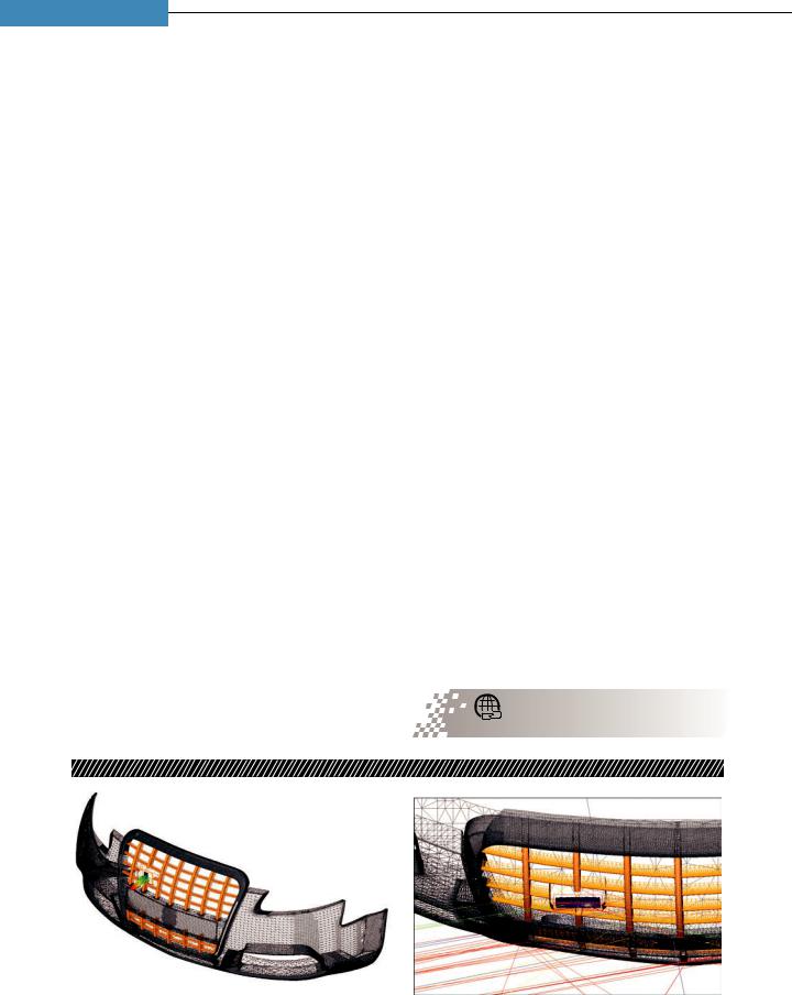
A radar sensor array model is installed in a proposed automobile fascia (left), and the ANSYS HFSS SBR+ shooting and bouncing rays EM field solver is applied to model the installation interactions. The HFSS finite-element simulation for the radar sensor antenna system is shown in the proper installation location, and a subset of rays employed by the HFSS SBR+ simulation is shown at an exit angle of 80 degrees.
34 I ANSYS ADVANTAGE |
ISSUE 1 | 2018 |
vk.com/club152685050 | vk.com/id446425943
“Radar systems play a central role in safety systems
and must be tested with vehicle control systems and algorithms to validate safe operation.”
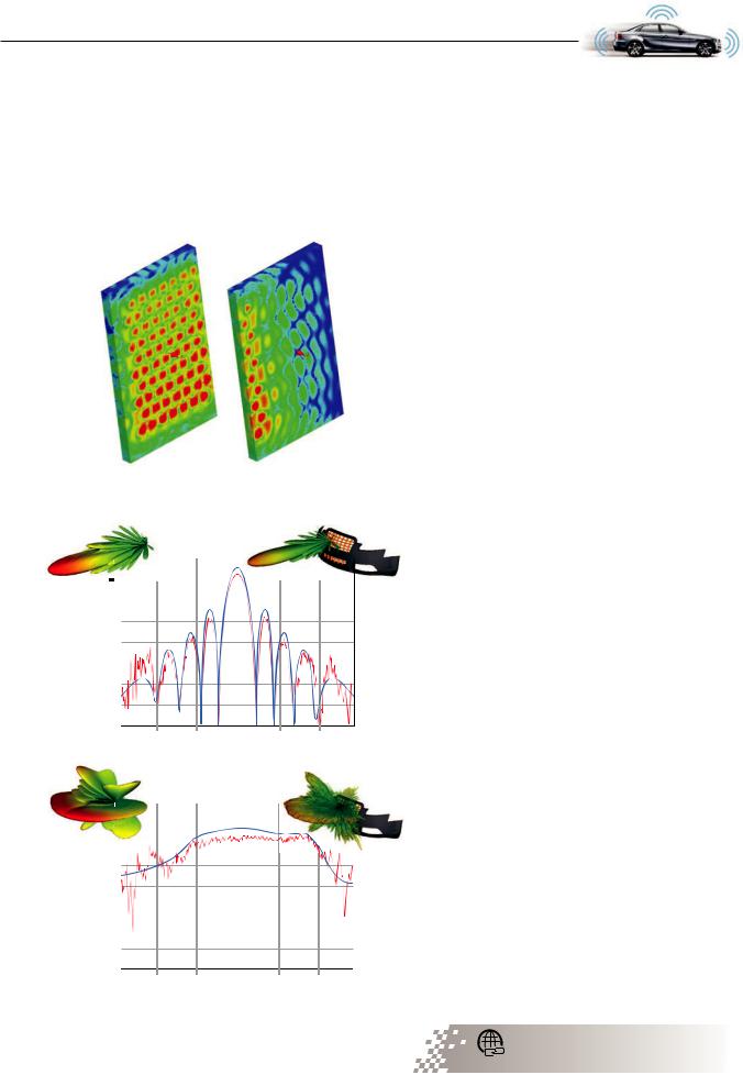
ANSYS HFSS–simulated near-fields surrounding sensor for Tx channel (left) and for Rx channel (right) form the basis for excitation in the HFSS SBR+ fascia interaction solution.
|
20 |
|
15 |
(dB) |
10 |
Gain |
5 |
|
|
|
0 |
-5
-10
-90 |
-60 |
-30 |
0 |
30 |
60 |
90 |
||
|
|
|
Azimuth (degrees) |
|
|
|
||
|
|
|
Sensor |
|
Sensor + Fascia |
|
|
|
|
|
|
|
|
|
|||
|
10 |
|
5 |
(dB) |
0 |
Gain |
-5 |
|
|
|
-10 |
|
-15 |
|
-20 |
-90 |
-60 |
-30 |
0 |
30 |
60 |
90 |
||
|
|
|
Azimuth (degrees) |
|
|
|
||
|
|
|
Sensor |
|
Sensor + Fascia |
|
|
|
|
|
|
|
|
|
|||
radar sensors are mounted either behind a bumper or in the vehicle fascia. The proximity effects of the vehicle design can affect the performance of the radar
— particularly the antenna’s ability to focus radar energy. The vehicle manufacturer develops bumper and fascia designs to be both aerodynamic and aesthetically pleasing to their buyers. The unique features of a body shape that meet aesthetic goals could negatively impact the performance of a radar sensor integrated into it or hidden behind it.
In the past, the effects of radar-to-fascia and radar-to-bumper interaction were evaluated through cooperation between the sensor manufacturer and the vehicle manufacturer. This was an iterative process based on trial-and-error prototyping. Valuable
development time and cost were invested in prototypes that required retooling as the car was redesigned.
Modeling and simulation reduces this process from as long as nine months to a matter of days. ANSYS HFSS SBR+ can integrate models, including highly accurate results from finite element ANSYS HFSS models, for the isolated sensor system, and simulate its interaction with the much larger fascia and bumper using its highfrequency ray tracing methods. The simulated installed radar antenna response shows the radar engineer
how each radar subarray will illuminate the road or environment when it is installed into the proposed fascia–bumper design.
Virtual Road Testing for Radar
Autonomous vehicle developers are devoted to the safety of passengers. Radar systems play a central role in safety systems and must be tested with vehicle control systems and algorithms to validate safe operation. Without the benefit of modeling and simulation, this would require driving millions of test miles. Today, most AV developers are moving this process to the domain of the digital prototype. In
modeling and simulation, testing can be performed for any conceivable scenario.
However, high-fidelity modeling of the electromagnetic performance of an automotive radar system has to this point proven to be a major challenge.
Receive channel subarray radiation pattern (top) and transmit channel radiation pattern (bottom) show radiation patterns for the module in isolation, and as installed to include fascia and bumper interaction.
Solve Large-Scale Problems in a Connected World ansys.com/large-scale
© 2018 ANSYS, INC. |
ANSYS ADVANTAGE I 35 |

vk.com/club152685050 | vk.com/id446425943
On the Radar (continued)
Full-physics modeling and simulation of radar sensors creates an enormous EM analysis problem as the radar needs to cover an area that could occupy over 1.4 million electrical wavelengths. This is compounded by system-level requirements that include the number of times the central control system is updated by radar, the number of antennas involved, the range and velocity resolution of the MRR system, and the comparative velocity of the environmental actors.
While these considerations pose challenges to high-fidelity EM modeling of radar–environment interaction, they are not insurmountable. An appropriate application of the shooting and bouncing rays (SBR) technique using ANSYS HFSS SBR+ can
Busy intersection environment geometry. Velocity of each moving actor in the scene is shown.
Shooting and bouncing rays traced from radar transmit channel throughout the environment. Multiple colors correspond to ordinal reflection for each ray track pictured.
Range-Doppler map for radar system over a radar frame of 200 consecutive 300 MHz pulses
Range profile for a single radar 300 MHz bandwidth pulse with 0.5 m resolution. Radar is visible in overlay at lower left. The range profile shows distance of flight for all radar echoes received by the radar system in response to the modeled environment. Very strong radar returns for some light posts, the surfaces of several of the vehicles, and between vehicle
reflections are shown. The signals are stronger from closer targets than from more distant targets, but even targets well down the road are detectable. Due to the waveform’s resolution, the radar may detect multiple target echoes from the same vehicle.
36 I ANSYS ADVANTAGE |
ISSUE 1 | 2018 |

vk.com/club152685050 | vk.com/id446425943
provide full-physics simulation of such problems with good accuracy and reasonable efficiency — in terms of both computer resources and modeling time.
ANSYS HFSS SBR+ can be used to synthetically reproduce the signals obtained by a high-fidelity radar model. Any specified bandwidth may be applied to the simulation to foster virtual innovation by enabling the engineer to test new waveforms that may not be currently available from sensor suppliers.
Radar signal processing systems need to intelligently group distributed target returns that belong to the same actor in the environment, or the vehicle control system will be overwhelmed with too many targets to track. This grouping is made possible by processing the possible Doppler-shift of the signals that bounce off surfaces with a velocity that is different from the observation domain. Radar signals from targets that have the same velocity in consecutive range bins can be considered to be from the same target. Accurate determination of targets in terms of both range and velocity requires a large number of pulses to be analyzed over time. ANSYS SBR+ results make it possible to develop RangeDoppler maps that show the range to the target returns on one axis and the extracted velocity of the targets on the other.
A typical automotive radar sensor provides updates to the vehicle control and safety systems at a rate of 5 to 30 frames per second. The speed and accuracy
of ANSYS HFSS SBR+ allows a complete simulation of the movement of vehicles through this environment to develop a Range-Doppler map over time for the scene. Placing the HFSS SBR+ simulation within the simulation loop of a complete autonomous vehicle creates a digital prototype to test the vehicle control system or active safety system.
Complete Modeling and Simulation Work Flows
Radar sensor developers, automotive OEMs, active safety systems developers and autonomous vehicle control systems developers use ANSYS solutions to design radar sensor modules, study their installed performance on the vehicle, and gain insight into radar reports for moving and stationary targets on a full, dynamic road scene. From a single component to a digital system prototype, ANSYS provides unique solutions for this very challenging high-frequency problem.
Autonomous Vehicle Radar: Improving Radar Performance with Simulation ansys.com/av-radar
“Radar systems play a central role in safety systems and must be tested with vehicle control systems and algorithms to validate safe operation.”
© 2018 ANSYS, INC. |
ANSYS ADVANTAGE I 37 |
vk.com/club152685050 | vk.com/id446425943
MANUFACTURING
Simulation and Additive
Manufacturing
Speed Tooling Design
By Mark Davey,
Principal Engineer,
Senior Flexonics Inc.,
Bartlett, USA
When tooling suppliers told Senior Flexonics engineers that considerable troubleshooting and cost would be required to validate tooling to manufacture finned tubes for a new compact liquid/air heat exchanger, they turned to ANSYS software. Employing ANSYS LS-DYNA
to simulate the stamping operation allowed them to design a progressive die prototype right the first time. They were able to produce the tool at a 95 percent lower cost and in 75 percent less time than the best supplier quote.
38 I ANSYS ADVANTAGE |
ISSUE 1 | 2018 |
vk.com/club152685050 | vk.com/id446425943
SENIOR FLEXONICS is developing a next-generation compact liquid/air heat exchanger (HEX) for multiple industrial and mobile applications. By using finned tubes to increase the heat transfer between the hot gas in the tubes and the cold water in the shell, the new HEX is smaller and lighter than current models. However, these finned tubes are challenging to manufacture because the high height-to-width ratio of the fins makes stamping difficult due to very high stresses and strains on both the
raw sheet and the progressive die. When |
|
|
the company took this new design to its two |
|
|
tooling suppliers, one said they could not |
|
|
do it and the other said it would take |
|
|
12 weeks and cost $60,000 because a |
|
|
lengthy trial-and-error process on the shop |
|
|
floor would be required to make a reliable |
|
|
tool. Senior Flexonics engineers decided |
|
|
to simulate the stamping operation using |
|
|
ANSYS LS-DYNA explicit dynamics software to |
die that produces good fins. |
|
speed the tool prototyping process. Simulation |
||
|
made it possible to identify and correct problems in an existing original progressive die design, select the right part material and validate the process of bending the finned sheets into a cylinder. Using additive manufacturing (3D printing), tooling developed employing simulation arrived in only three weeks, at a cost of $3,000, and worked perfectly the first time.
New-Generation HEX
Senior Flexonics produces industrial heat exchangers, as well as EGR coolers for heavy-, mediumand lightduty trucks, high-pressure diesel fuel tubes and rails, water tubes, turbo oil drain lines, metal bellows, piston cooling jets, and complex assemblies.
The company’s engineers designed its newest
HEX to increase heat conduction between the hot and cold fluids so that the cooler was smaller and lighter, both important advantages in the automotive and trucking markets. To do this, they designed longitudinal fins within the tubes that increase the contact area between the hot gas in the
tubes and the cold liquid in the shell of the heat exchanger.
When Senior Flexonics engineers asked their tooling suppliers for quotes to build the progressive die tooling needed to manufacture the fins, the suppliers pointed out that the depth of the fins forced the stainless steel material to the edge of
its formability limits. They said it would be very
difficult to predict in advance a tooling geometry that would provide the correct final shape. They were also concerned about tearing in high-stress areas. They expected that a trial-and-error process would be required to meet the design specifications.
Simulating the Stamping Operation
Senior Flexonics engineers decided to design the tool internally and to contract a 3D printing service bureau to build it. The engineers were not familiar with ANSYS LS-DYNA, but
they were able to quickly and easily set up the simulation due to their familiarity with the ANSYS Workbench environment.
They extracted an initial tool design in CAD software and opened the CAD model in Workbench. Engineers generated the finite element mesh in Workbench using the automatic multizone method. They modeled
Additive Manufacturing and Topology Optimization ansys.com/additive-topology
© 2018 ANSYS, INC. |
ANSYS ADVANTAGE I 39 |
vk.com/club152685050 | vk.com/id446425943
Speed Tooling Design (continued)
“Simulation made it possible to obtain appropriate dies on first delivery, which saved tens of thousands of dollars and enabled the company to meet the
product launch schedule.”
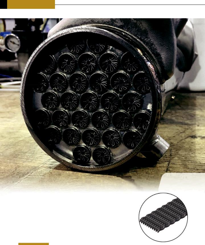
Printed tooling installed in stamping press
the tool as 17-4 PH stainless steel solid elements and the raw material as 400-series stainless steel shell elements. The model included 64,230 nodes and 67,112 elements. To model a strip of material pulled out of a feed chute they used a friction element to apply forces to mimic those required to unwind
and pretension the strip from the coil. Engineers wrote a user-defined function to describe a time- dependent sinusoidal displacement
function that provides gradual startup and slowdown on each stroke of the die to ensure a stable solution.
ANSYS LS-DYNA iterated to a transient solution of four stamping cycles in
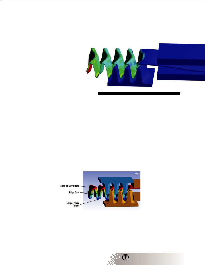
38 hours. The simulation displacement results showed that the part produced by an existing initial tool design would have curled at its crown
and walls where it was supposed to be relatively flat, and that the radius at the root of the fin was too large. The strip-forming strain results showed considerable tearing. Based on the simulation results, Senior Flexonics engineers adjusted the tool geometry to counteract the distortion problems. They changed the material to 316L stainless steel to address the
tearing problem. After only a couple of iterations, the simulation predicted that the new progressive die design would produce parts of the right geometry and limit tearing to just the first fin on the strip,
which was acceptable. The tooling stress results showed that the tooling could easily withstand the forming process. Based on these results, Senior Flexonics engineers ordered the prototype tool from a 3D printing service bureau.
Simulating the Tube
Forming Operation
While they waited for the progressive die to be
delivered, Senior Flexonics engineers turned their attention to developing
a process to form the finned strip into a cylinder for insertion into a tube. They first used LS-DYNA to simulate
a compression bending technique. The simulation results showed that this approach would not bring the ends of the fins together to form a full cylinder.
Next, they simulated a tangential wiping system, but this method also did not fully close off the cylinder. Finally, they simulated a rolling process that provided considerably better results but still did not quite fully
40 I ANSYS ADVANTAGE |
ISSUE 1 | 2018 |

vk.com/club152685050 | vk.com/id446425943
form the cylinder. Engineers modified the rolling die design, decreasing the diameter at the outlet so that the rolled cylinder popped out of the tool for springback insertion into a tube. Simulation showed that
this approach provided
a tight seam, so the rolling die was also procured from a 3D printing service bureau.
When the prototype progressive die was received, Senior Flexonics engineers installed it in a stamping press and ran a short strip. The results closely matched the simulation predictions and met all
design specifications. The rolling die also matched the simulation by working correctly the first time. Without simulation, the chances are that both the progressive die and the rolling die would have required expensive repairs
and possibly even rebuilding to resolve the problems that
were identified in simulation. Simulation made it possible to obtain appropriate dies on first delivery, which saved tens of thousands of dollars and enabled the company to meet the product development schedule.
Second fins produced on optimized 3D printed tool matched revised simulation predictions.
Second-generation rolling die correctly seals tubes.
© 2018 ANSYS, INC. |
ANSYS ADVANTAGE I 41 |
vk.com/club152685050 | vk.com/id446425943
AUTOMOTIVE
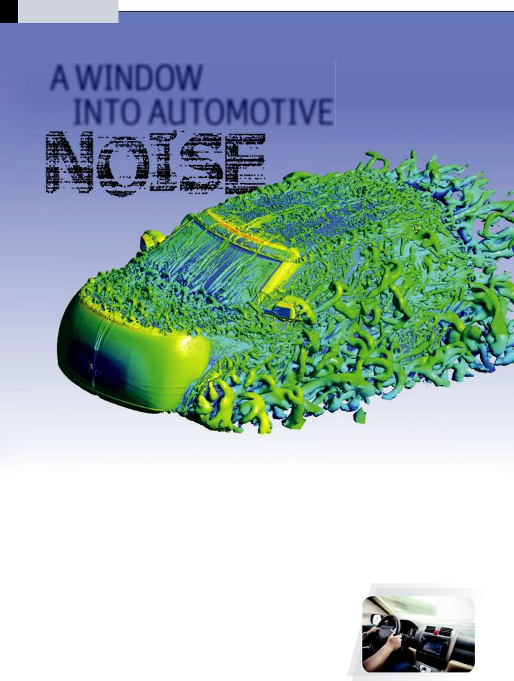
A WINDOW
INTO AUTOMOTIVE
The interior of a vehicle can be distractingly loud |
|||
due to wind turbulence, especially at highway |
|
||
speeds. At Corning, engineers combined |
Most drivers understand that they have to |
||
aerodynamic and vibro-acoustic analysis in |
|||
turn up the radio on the highway if they |
|||
ANSYS Workbench to determine how glazing |
want to hear their favorite station, or speak |
||
louder if they want to have a conversation |
|||
can help control interior noise. |
|||
with their passengers. This is the direct result |
|||
|
|
of the turbulent air flowing around their vehicle |
|
By Chao Yu, |
when driving at high speed. Recent studies by J.D. Power on U.S. vehicle |
||
Senior Project Engineer, |
dependability [1] have reported that |
||
Advanced Machine Systems, |
excessive wind noise was one of the top |
||
problems most commonly experienced |
|||
Corning Incorporated, |
|||
by vehicle owners. Depending on where |
|||
Corning, USA |
|||
the exterior noise falls in the frequency |
|||
|
|
||
|
|
||
|
|
spectrum, vehicle occupants may perceive |
|
|
|
that noise as falling anywhere between a |
|
|
|
quiet conversation (40 to 50 decibels, or |
|
|
|
dB) and a busy city street (70 to 80 dB). |
|
42 I ANSYS ADVANTAGE |
ISSUE 1 | 2018 |