

ANSYS Polyflow
.pdfvk.com/club152685050 | vk.com/id446425943
ANSYS Mechanical predicts the impact of temperature on stress, strain and deformations on the die.
copper

 that
that  and chip,
 -level using ANSYS chip thermal models (CTMs) to
solve for a complete chip-and-package co-analysis. The temperature profiles from the analysis can then be used inside ANSYS Mechanical to predict
the impact of temperature on stress, strain and deformations generated by
thermal or mechanical loading on the die. At the board level, the ANSYS SIwave signal integrity analyzer can be used to compute Joule heating in printed circuit board (PCB) traces and vias to create a board trace map and current density predictions. This is exported to the ANSYS Icepak systems-level thermal simulation tool, which calculates the orthotropic thermal conductivity of the PCB and temperatures at every point in the solution domain. These temperatures are transferred back to SIwave to update the electrical properties of the board based on the temperature field. SIwave and Icepak then iterate until the temperatures converge. The temperatures are used to load a structural model of the board and predict stresses and deformations.
Electrostatic Discharge
The smaller feature sizes and isolated and independent power/ground networks often found in advanced process nodes increase the risk of electrostatic discharge (ESD) failures. The traditional approach to ESD verification involves following engineering guidelines in creating the layout and running design rule checks. But these methods cannot predict if the overall resistance and current density of the ESD paths are below the threshold limit.
ANSYS PathFinder uses block-level static and dynamic techniques as well as fullchip level static methods to identify weak areas in the design and determine whether or not it meets ESD guidelines. PathFinder verifies the effective resistance between any two pads/bumps traversing the network through a clamp cell; between pads/ bumps to every connecting clamp cell; between multiple clamp cells; and between active devices and clamp cells for pass/fail checks. PathFinder estimates the effective resistance from the devices in the IC to the clamp cells that are inserted to provide
a discharge path. PathFinder highlights the wire/vias that fail the current density limits, allowing the designers to verify that the current flow during a discharge event is within the established limits defined by technology or process guidelines.
The safety of ADAS and autonomous driving systems is only as good as the reliability of the electronic systems they run on. ANSYS simulation tools enable engineers to perform EM analysis based on the temperature experienced by each wire on the chip. This approach saves time by highlighting the truly problematic traces. ANSYS thermal simulation tools further enable engineers to evaluate the complete thermal ecosystems to identify and correct thermal problems at the die, package, board and system level. Finally, ANSYS simulation tools enable engineers to identify and troubleshoot ESD problems. The ability to identify and troubleshoot reliability issues with simulation enables companies to ensure the reliability of ADAS and autonomous driving electronics in a rigorous yet efficient fashion, making it possible to achieve substantial reductions in time to market and improving reliability.
Fast Tracking ADAS Autonomous Vehicle Development with Simulation ansys.com/fast-tracking
“The safety of ADAS and autonomous driving systems is only as good as the reliability of the electronic systems they run on.”
© 2018 ANSYS, INC. |
ANSYS ADVANTAGE I 23 |
vk.com/club152685050 | vk.com/id446425943
SENSOR SIMULATION
On the
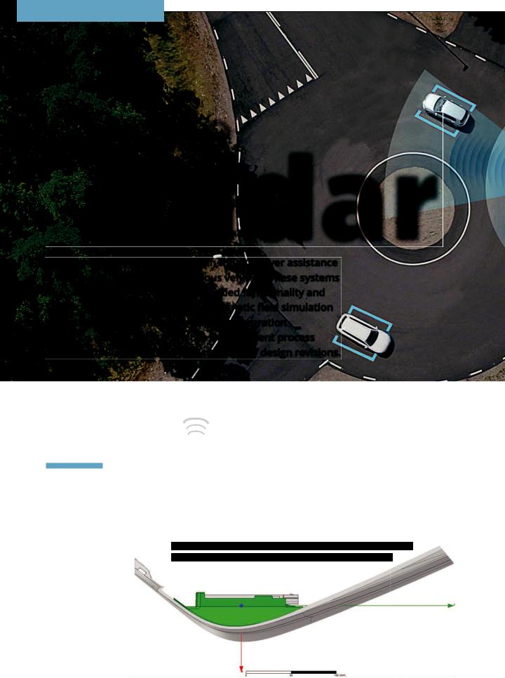
Radar
Radar systems play a critical role in today’s driver assistance systems and upcoming autonomous vehicles. These systems must be accurate to provide the needed functionality and safety. Autoliv uses ANSYS electromagnetic field simulation software to evaluate alternative radar integration
scenarios early in the automotive development process
to pioneer reliable systems and avoid costly design revisions.
By Clyde Callewaert,
Principle RF Engineer,
Autoliv Electronics,
Southfield, USA
Vehicle safety and autonomous driving require ever-increasing
numbers of radar systems looking outward at the vehicle’s environment. The packaging design of these radar systems is carried out early in the vehicle development process, before a prototype vehicle is available for performance testing. If engineers
get the design wrong, the packaging process may have to be repeated at a cost of about $1 million and possible delays to the vehicle launch. Autoliv, the worldwide leader in automotive safety systems, avoids these costs by using ANSYS HFSS
to predict how the fascia and other nearby components affect radiation patterns so they can validate the design long before the prototype phase.
For example, many of today’s vehicles are equipped with blind spot detection
Fascia top view with radar sensor mounting bracket shown in green
24 I ANSYS ADVANTAGE |
ISSUE 1 | 2018 |
vk.com/club152685050 | vk.com/id446425943
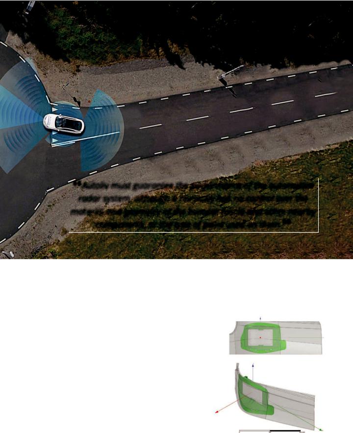
“Autoliv must guarantee the performance of the automotive radar system, although it normally has no control over the material and geometry of the bumper fascia and other nearby components, or the type of paint used on them.”
presence, direction and speed of vehicles in adjacent lanes. If a vehicle is present in either of the driver’s blind spots, a warning indicator on the side view mirror lights up. Many current vehicles also have a radar sensor in the middle of the front bumper to enable features such as forward collision warning, which detects vehicles or objects that the driver might hit if not noticed. Fully autonomous vehicles are expected to have these and more radar systems mounted behind the bumper fascia and other body panels.
Radar systems use a transmitter to emit a short pulse of electromagnetic radiation. After each pulse, the transmitter is turned off and a receiver listens for signals caused by the pulse reflecting off nearby objects. Electromagnetic radiation emitted by a radar sensor may be distorted in difficult-to-predict ways by objects that the radiation must pass through. Other nearby objects may generate reflections that interfere with the receiver. When integrating a radar sensor in a new vehicle, engineers
must position the system so that the fascia and mounting bracket do not interfere with its accuracy. This means obtaining a high and relatively constant signal across the azimuth (from side to side) of the sensor while minimizing wasted energy delivered to undesired directions or reflected by the bumper fascia back to the radar. The geometry of the bumper fascia is often complex because it has to meet multiple goals that
include durability, safety, aesthetics and manufacturability. A slight change in sensor position can be the difference between meeting or not meeting accuracy requirements. Autoliv must guarantee the performance of the
Truncated section of CAD file of bumper fascia used for simulation, with radar sensor position
© 2018 ANSYS, INC. |
ANSYS ADVANTAGE I 25 |

vk.com/club152685050 | vk.com/id446425943
On the Radar (continued)
“If, during drive testing, Autoliv engineers discover that the position of the radar or bracket geometry makes it impossible to meet the performance requirements, the entire process must be repeated
at a cost approaching $1 million.”
Sensor transmit radiation pattern without fascia
Sensor transmit radiation pattern with fascia
automotive radar system, although it normally has no control over the material and geometry of the bumper fascia and other nearby components, or the type of paint used on them.
Impact of Packaging Design on Radar Accuracy
To meet the vehicle launch date, Autoliv must first create the packaging design. This mainly consists of determining the best position for the sensor in relation to the fascia and designing the mounting bracket, before the vehicle or even the fascia is available for testing. Autoliv invests
significantly in packaging design, instrumenting the vehicle prototypes with measurement equipment and in test driving in many different environments
to evaluate the accuracy of the radar. If, during drive testing, Autoliv engineers discover that the position of the radar or bracket geometry
makes it impossible to meet the performance requirements, the entire process must be repeated at a cost approaching $1 million. The additional design iteration also adds eight to 12 weeks in lost program time, which could potentially delay the vehicle launch.
Simulating Radar Performance in the Vehicle
Autoliv avoids this potential problem by using ANSYS HFSS to digitally explore and evaluate radar sensor packaging designs before prototyping. HFSS has demonstrated predictive power in many different programs and applications. The simulation process begins by obtaining physical samples of the bracket and fascia materials to determine their electrical properties, which are required to run accurate electromagnetic simulations, using either waveguide or quasi-optical techniques. The measured electrical properties include the dielectric constant and loss tangent of the fascia, paint layer
and bracket.
Autoliv engineers use a computer-aided design (CAD) file from the automobile’s original equipment manufacturer (OEM) that contains the current geometry of the bracket, fascia and other nearby components. ANSYS SpaceClaim is used to translate and prepare
the CAD for HFSS import and meshing improvement. They truncate the fascia in the simulation model to both conserve computational
resources and preserve electromagnetic fidelity. Engineers have already created ANSYS HFSS models of all of the company’s current radar systems. They select the radar system to be used on the vehicle and position it within the bracket of the simulation model as an initial design according to Autoliv packaging guidelines. Then engineers assign measured electrical properties of the fascia, paint and bracket to their respective objects within the model. The simulation is run employing ANSYS HFSS, ANSYS HFSS-IE solver and ANSYS High-Performance Computing.
Autonomous Vehicle Radar: Improving Radar Performance with Simulation ansys.com/av-radar
26 I ANSYS ADVANTAGE |
ISSUE 1 | 2018 |
vk.com/club152685050 | vk.com/id446425943
5 |
|
|
|
|
|
|
|
|
|
|
4 |
|
|
|
|
|
|
|
|
|
|
3 |
|
|
|
|
|
|
|
|
|
|
2 |
|
|
|
|
|
|
|
|
|
|
1 |
|
|
|
|
|
|
|
|
|
|
Error |
|
|
|
|
|
|
|
|
|
|
0 |
|
|
|
|
|
|
|
|
|
|
-1 |
|
|
|
|
|
|
|
|
|
|
-2 |
|
|
|
|
|
|
|
|
|
|
-3 |
|
|
|
|
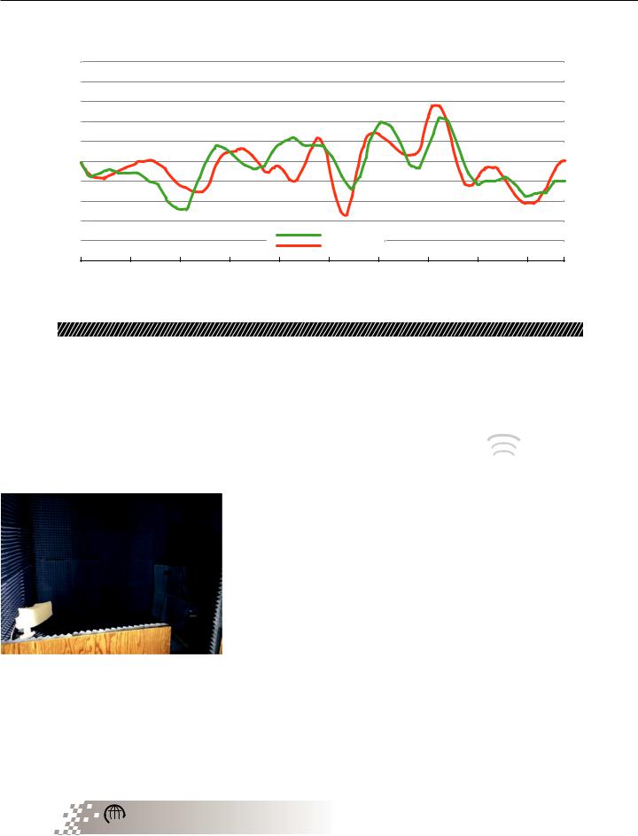
Measured |
|
|
|
|
|
-4 |
|
|
|
|
|
|
|
|
||
|
|
|
|
Simulated |
|
|
|
|
||
|
|
|
|
|
|
|
|
|
||
-5 |
|
|
|
|
|
|
|
|
|
|
-50 |
-40 |
-30 |
-20 |
-10 |
0 |
10 |
20 |
30 |
40 |
50 |
Azimuth Angle0
Predicted versus measured radar sensor bearing prediction error
Meeting Accuracy Requirements
The simulation results are then post-processed in HFSS and exported into a custom MATLAB program that mimics the algorithm used by the radar sensor to evaluate radar performance, including signal-to-noise ratio, field of view, bearing bias and bearing ambiguity. It allows engineers to determine, for example, the maximum distance at which the radar can detect an object with a given radar cross section at a given azimuth angle,
such as an oncoming motorcycle in the next lane at a distance of 30 meters. If predicted performance does not meet minimum requirements,
geometrical countermeasures are necessary, such as relocating the radar, and then the simulation process repeats. The geometry of the fascia is also likely to change during the design process, but when changes occur, Autoliv engineers obtain the new geometry, run their simulations again and, when necessary, modify their design.
Integrating a radar sensor into a vehicle so that it will deliver the high levels of accuracy required to meet government regulation and customer expectations is a
challenging task. Autoliv engineers have used ANSYS HFSS electromagnetic field simulation software to integrate many radar systems into new vehicles without a single issue that required an additional design iteration. Simulation also has helped engineers identify improvements in packaging
design that made it possible to substantially increase the range and accuracy of the radar system.
Radar Road Trip  ansys.com/road-trip
“Autoliv engineers have used ANSYS HFSS to integrate many radar systems into new vehicles without a single issue that required an additional design iteration.”
© 2018 ANSYS, INC. |
ANSYS ADVANTAGE I 27 |

vk.com/club152685050 | vk.com/id446425943
SENSOR SIMULATION
Autonomy on Roadways and Railways
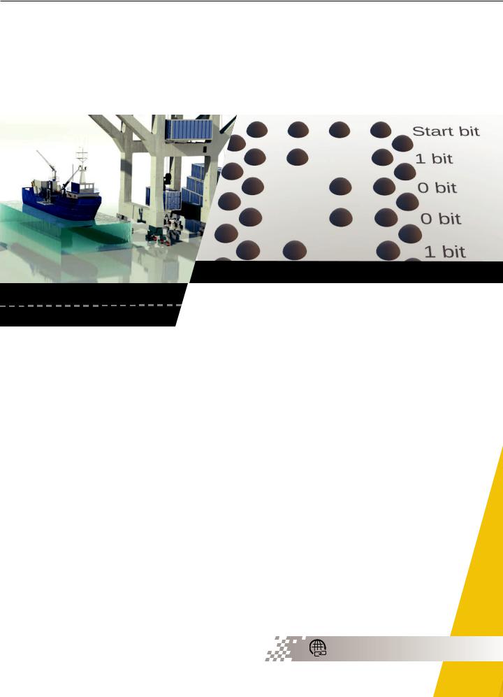
RPS reads coded paint drop bit patterns on road.
The success of autonomous vehicles depends on both changes in the vehicles themselves and the transportation infrastructure. Autodrive is developing technology that uses plastic code markers on roads and rail tracks to precisely locate a vehicle. Such precision can increase the safety and the traffic capacity of infrastructures and reduce energy consumption on railways. It can also
help to avoid automobile collisions and provide a powerful tool to achieve Level 5 autonomous driving. Simulation and modelbased development code is critical in creating the certified embedded software that controls the hardware in these systems.
By Alejandro Badolato,
Founder and CEO,
Autodrive Solutions,
Madrid, Spain
28 I ANSYS ADVANTAGE
vk.com/club152685050 | vk.com/id446425943
“ANSYS SCADE proved to be absolutely critical to Autodrive engineers, saving the company 80 percent in development time in getting RPS to market.”
A 64-bit paint drop code provides precise roadway mapping used by RPS.
centimeter precision. This valuable data can be shared with the central host.
A mapping vehicle will drive on every lane of the city when the paint drops are completed. It will log every 64-bit pattern and create a map of each centimeter of the roadway to serve as a reference map. While such precise mapping of every road may seem prohibitively complex and expensive, existing automated line painting trucks could be easily modified to deposit paint drops instead of lines. Autodrive engineers, taking into account data provided by the Los Angeles Department of Transportation, have determined that the entire 44,900 km of driving lanes in Los Angeles could be coded with paint drops in two months by 50 trucks painting at a rate of 6 km/h.
In everyday operation, a radar unit containing four separate millimeter-wave (mm-wave) radar detectors located under an autonomous car will read the four paint spots in each row as the automobile passes over them. This reading is achieved through the mm-wave radar’s ability to measure the distance to the ground with 0.1 mm accuracy every 50 µs. In this way, each radar is able to obtain a high-detail profile of the ground while the vehicle is running, detecting the presence or absence of a paint-drop due to its thickness.
After reading the entire 64-bit code, the vehicle is located with 1 centimeter accuracy. The road map stored in the memory of the vehicle will anticipate the road
shape ahead and update the position by reading row by row instead of waiting for a complete 64-bit-code read. This is possible because the next 64-bit-code sequence is already known. Therefore, the vehicle can set the optimum trajectory for driving safely using the road shape embedded in the road map.
The extreme accuracy of RPS enables data sharing between vehicles by transferring the vector of each target from one car to another. In this way, the autonomous car can use the information gathered not only by its own sensors but from a vehicle that is driving 100 m ahead, improving the vehicle’s perception. It will also transmit its location to the central host traffic controller, which will use the information from all vehicles to control the flow of traffic in that region.
The Radar Position System
Autodrive’s Radar Position System (RPS) uses the miniaturized, low-cost, high-resolution mm-wave radar sensor developed by the European Union’s SUCCESS consortium in its radar units. The surface-mountable package of this fully integrated 122 GHz radar sensor is 8 mm by 8 mm and includes an SiGe chip along with transmitting and receiving antennas. Four of these sensors are housed in sealed, weatherproof plastic units connected to the chassis under an autonomous vehicle. The system is absolutely secure — it is
Installed Antenna Performance ansys.com/installed-antenna
© 2018 ANSYS, INC. |
ANSYS ADVANTAGE I 29 |
vk.com/club152685050 | vk.com/id446425943
Autonomy on Roadways and Railways (continued)
“Continual speed adjustments could result in a
savings of 20 percent of the 8 billion euro
energy cost of the European train fleet each year.”
|
impossible to jam the radar because it has a very high frequency of 122 |
The lens was essential to |
||
|
GHz and a huge bandwidth of more than 15 GHz. Any manipulation of the |
the operation of the RPS, but |
||
|
track is easily detected as it will generate a mismatch with the recorded |
perhaps even more critical was |
||
|
road map. |
|
|
the development of the embedded |
|
A customized plastic lens had to be developed to focus the radar |
software that must control the |
||
|
waves into a 1-cm circle over the ground to achieve the 1-cm |
hardware flawlessly to meet the |
||
|
positioning accuracy of the RPS. Autodrive engineers used ANSYS |
EU’s rigid certification standards. |
||
|
HFSS SBR+ — the industry-leading tool for simulating installed |
While Autodrive Solutions had a lot |
||
|
antenna performance on electrically large platforms, including |
of experience with radar systems, |
||
|
the applications of predicting installed radiation patterns, field |
they had little with critical real-time |
||
|
distributions and antenna-to-antenna coupling — to successfully |
embedded software. So they turned to |
||
|
design the lens. |
|
|
ANSYS SCADE to generate, validate and |
|
|
|
|
obtain certification for their software. |
|
|
|
|
SCADE proved to be absolutely critical |
|
|
|
to Autodrive engineers working on this |
|
|
|
|
application, saving the company 80 percent |
|
|
|
|
in development time in getting RPS to |
|
|
|
|
market. The engineers focused on the model, |
|
|
|
|
on solving the problem, and let SCADE develop |
|
|
|
|
certifiable software to control the hardware they |
|
|
|
|
developed. If they found after testing that there |
|
|
|
|
was a problem with the model, they simply had to |
|
|
|
|
modify the model to solve the problem. SCADE then |
|
|
|
|
took this model to generate the code with the certified |
|
|
|
|
KCG compiler to provide the traceability and the |
|
|
|
|
documentation required by the certification authorities |
|
|
Four-radar RPS reading paint dot bit pattern on road |
in a few minutes. SCADE-generated software met the |
||
|
|
|
certification standards for embedded software in critical |
|
|
Due to a small wavelength (lambda less |
|
safety applications every time. |
|
|
than 3 mm) and a big simulation volume (100 |
|
Railway Applications |
|
|
lambda by 100 lambda by 400 lambda), the |
|
||
|
problem has to be divided for optimizing |
|
Though it seems less obvious, the railway industry also has |
|
|
computing requirements. A first simulation |
|
challenges that can be solved using autonomous systems. |
|
|
of the patch antennas is obtained using |
|
Determining the precise location of a train on a track is not as |
|
|
the finite element method solver from |
|
easy as it might seem. Because of this, the cost of stopping a |
|
|
ANSYS HFSS. Then the simulation |
|
train accurately, which is required for deploying platform screen |
|
|
results are used to excite the radiating |
|
doors (to prevent people from falling or jumping onto the tracks), |
|
|
source in HFSS SBR+, which leverages |
|
is 0.5 million euros per train station. With the current technology, |
|
|
the asymptotic Shooting and |
|
when a train passes an RFID unit, a preprogrammed braking process |
|
|
Bouncing Ray Plus (SBR+) technique |
is automatically initialized. This process can estimate where the train |
||
|
to efficiently compute accurate |
will stop. The high cost of stopping a train accurately is due to the |
||
|
solutions. |
continuous calibrations required for each train because the braking |
||
30 I ANSYS ADVANTAGE |
ISSUE 1 | 2018 |
vk.com/club152685050 | vk.com/id446425943
process depends on multiples variables such as the number of coaches, the load, the wear of the wheels and so on.
Autodrive Solutions developed a solution similar to the one they created for roadways. In this case, instead of dots of paint, they install bars of plastic either 1-cm or
2-cm high in a cluster at multiple points along the train tracks. A 1-cm-high bar represents a digital 0, and a 2-cm-high
bar represents a digital 1. A cluster of these bars can therefore encode the location of the train on the track in a series of digital bits that can be read by a single RPS unit attached to the bottom of the train’s engine car.
By measuring the time it takes for the train to travel between specific locations, they can determine precisely how fast the train is traveling at each point and apply
a customized braking process tailored to the load of the train. The adaptive braking system gives operators precise control over where the train will come to a stop.
RPS can also increase the amount of traffic that can be safely handled on a given railway by reducing the headway — the distance separating two consecutive trains. In Europe today, a track is divided into segments called “block sections” that have a minimum length of 400 meters; if one train is in a segment, no other train can enter that segment. This 400-meter separation, which is designed for safety, produces bottlenecks
that limit the number of trains traveling through an area. The bottlenecks occur most frequently near train stations and cities, where trains run at slow speeds.
Autodrive’s accurate positioning RPS can reduce the headway by reducing the block section length to only 50 meters, significantly reducing bottlenecks.
Finally, Autodrive’s RPS also increase the energy
efficiency of train systems. Today, European trains travel between two consecutive RFID beacons at a fixed speed. When
the train detects a signal indicating it can speed up or slow down in the next segment, it does so. The RPS can detect when track conditions change at smaller intervals. It can tell if the slope is uphill or downhill
and adjust the speed for these conditions immediately, without waiting for a signal in the next Eurobalise (European Standard RFID signaling device). Continual speed adjustments could result in a savings of
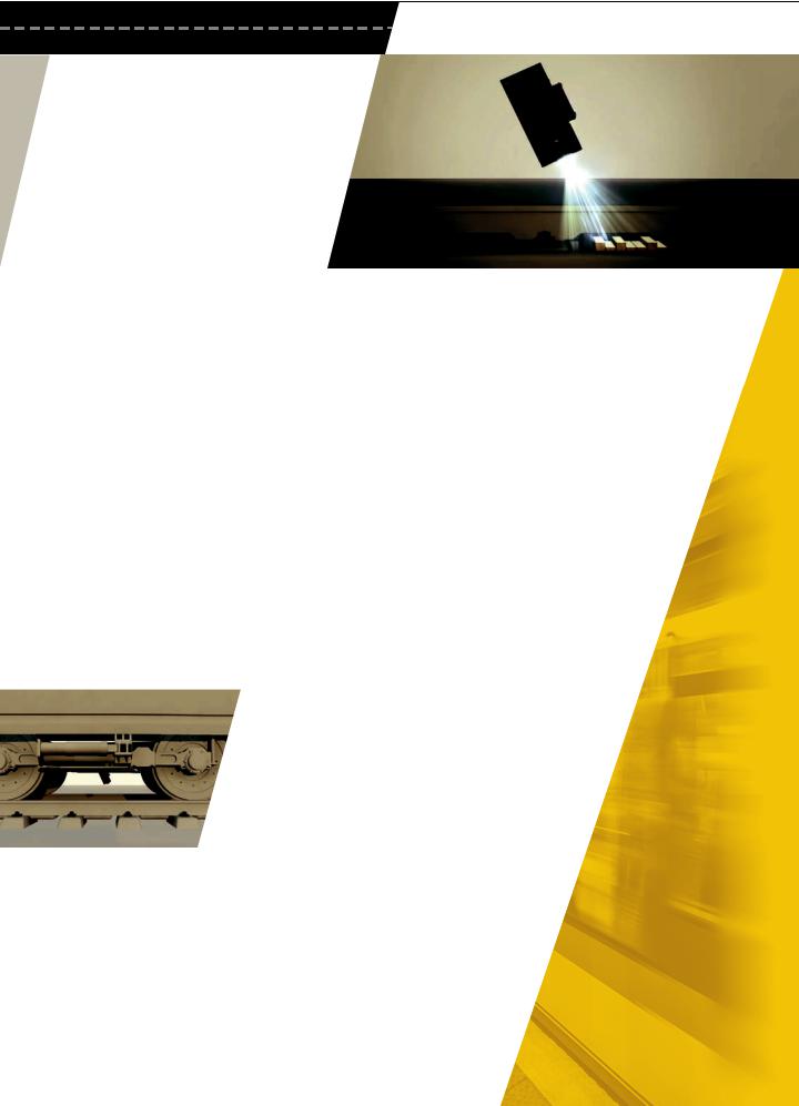
Single RPS railway unit reading height of plastic bars on train tracks
20 percent of the 8 billion euro energy cost of the European fleet each year.
Autodrive has successfully tested a prototype of the RPS in Metro de Madrid. They have also tested the measuring capabilities of the radar in a high-speed train traveling at 330 km per hour.
Using embedded software generated by ANSYS SCADE, Autodrive expects to achieve the SIL4 (Safety Integrity Level 4) certification as specified in standard EN 50128 during 2018, which will allow them to sell their technology on the European railway market soon.
Future Plans
Autodrive Solutions’ RPS has possible future applications for aircraft that are taxiing on a runway and for
optimizing the speed and braking of the Hyperloop. They are collaborating with departments of transportation, as
well as metro and train authorities, in various cities around the world to explore the possibility of using the RPS to improve roadway
and railway transportation safety and efficiency. ANSYS SCADE and ANSYS HFSS SBR+ simulations will be part of every solution they develop throughout the world.
© 2018 ANSYS, INC. |
ANSYS ADVANTAGE I 31 |
vk.com/club152685050 | vk.com/id446425943
SENSOR SIMULATION
|
|
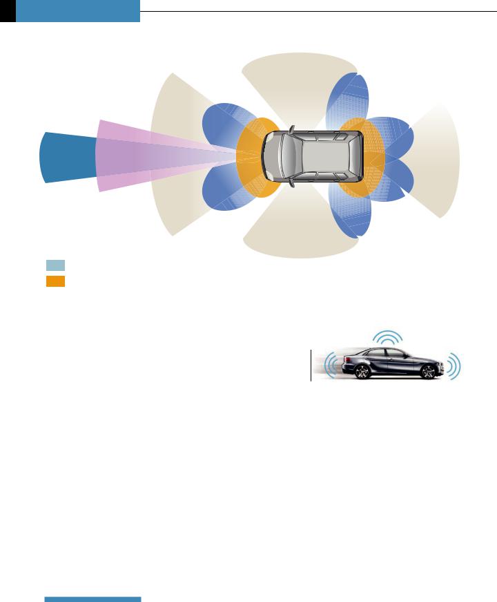
Surround View |
|
|
|
Blind Spot |
|
|
Traffic Sign |
Detection |
|
|
Cross Traffic |
|
|
|
Recognition |
|
|
|
Alert |
|
|
|
|
|
|
Adaptive |
Emergency Braking |
|
Parking |
Pedestrian Detection |
|
Assistance/ |
|
Cruise |
|
||
Control |
Collision Avoidance |
Rear |
Surround View |
|
|
|
|
|
Collision |
|
|
Traffic Sign |
Cross Traffic |
Warning |
|
|
|
||
|
|
Alert |
|
|
|
|
Recognition |
|
|
|
|
|
|
|
|
Long-Range Radar |
|
|
|
|
|
|
|
|
|
LIDAR |
|
|
Surround View |
|
|
|
||
|
Camera |
|
|
|
|
|
|
|
|
|
|
|
|
Short-/Medium-Range Radar
Ultrasound
Autonomous
Vehicle Radar:
Improving Radar Performance with Simulation
By Shawn Carpenter,
Product Manager,
High Frequency Electronics,
ANSYS
Autonomous vehicles require the continued evolution of vehicle sensors — the eyes and ears of the control system that perceive the operational characteristics of the
vehicle and the environment around it. The sensors feed the vehicle control systems with data on the current and developing state of the vehicle’s surroundings. Both operation and safety depend on the accuracy of the sensor system.
Four major classes of vehicular sensors provide the lion’s share of environment sensory data for an autonomous vehicle — visual spectrum cameras, laser-ranging devices (lidars), ultrasound sensors and radio frequency ranging sensors (radar). Automotive radar employs millimeterwave frequencies for long-range object and obstacle detection, as well as for tracking the velocity and direction of the various actors such as pedestrians, other vehicles, guardrails, etc., in the environment around the vehicle.
32 I ANSYS ADVANTAGE |
ISSUE 1 | 2018 |