

ANSYS Polyflow
.pdfvk.com/club152685050 | vk.com/id446425943
To help mitigate this problem, engineers at Corning [2] have been studying the physical mechanism by which exterior wind translates into cabin noise. At highway speeds, the air surrounding a vehicle is disturbed by the vehicle’s front end, the A-pillar (windshield support structure) and side mirrors. This results in turbulent flow that causes fluctuations in the
air pressure field on the outer surface of |
AERODYNAMICS |
|||
the vehicle. These pressure variations |
||||
cause the glazing (windshield and |
|
|
|
|
other window glass) to vibrate, |
|
|
|
|
which in turn excites the cabin air |
|
|
|
|
and generates some of the interior |
|
|
|
|
noise. Another major cause of interior |
|
|
|
|
noise is the wind on the rest of the |
CFD meshing |
|
|
|
|
|
|||
automobile surfaces being transmitted |
|
|
||
|
|
|
||
through the automobile parts to the |
|
|
|
|
cabin (flanking noise). In addition, the |
|
|
|
|
sound generated by tires in contact |
|
|
|
|
with the road and by the operation of |
|
|
|
|
the automobile’s mechanical systems |
Turbulence model |
|||
contributes to cabin noise. |
||||
|
|
|
||
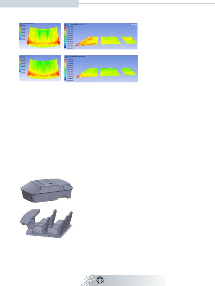
Corning engineers wanted to |
Full-vehicle wind noise model illustrates the combination of aerodynamic |
|||
determine which glass surfaces |
||||
modeling with vibro-acoustic modeling used in the DAVA method. |
||||
were the most important paths |
|
|
|
|
for glazing noise transmission, and also whether lighter-weight glass |
||||
material would have an impact. The team employed a simulation method called deterministic aero-vibroacoustics (DAVA) using fluid and structural analysis tools in ANSYS Workbench. The DAVA process began with a simplified geometry of a common U.S. sport-utility vehicle to reduce the cost of meshing and overall computation. Because the study focused on sound transmission through glazing, detailed vehicle features in the regions surrounding the glass — such as mirrors and the A-pillar — were maintained, while areas around the bumpers and tires were modeled with less detail. Taking advantage of symmetry, the engineers used ANSYS CFD meshing capability to create a computational fluid dynamics (CFD) mesh of 55 million hexcore cells to model the fluid domain surrounding half
of the vehicle geometry. The size of the domain was chosen so that vortex shedding, flow separation and reattachment phenomena could be captured.
Noise Generation |
Hood–windshield step |
A-pillar |
|
|
|||
Once the mesh was complete, Corning’s |
|
|
|
engineering team used the ANSYS Fluent |
|
|
|
CFD solver to simulate the transient |
|
|
|
turbulent flow in the domain. To |
|
|
|
predict the vortices generated by |
|
|
|
80 mph air flow over the vehicle, the |
|
|
|
engineers chose to use the detached |
|
|
|
eddy simulation (DES) model. DES is |
Front tire–bumper gap |
Side mirror |
|
a hybrid formulation that switches |
Main vortex shedding regions from the turbulent flow field using the |
||
between the standard Reynolds- |
|||
Q-criterion, colored by velocity magnitude |
|||
averaged Navier-Stokes (RANS) |
|||
|
|
||
solution and large eddy simulation (LES) modeling based on the mesh |
|||
resolution and distance from the wall. LES is computationally more |
|
||
expensive, and was used in the coarser domain away from the vehicle, while RANS was used to solve the more finely resolved areas at the wall boundaries. The team ran the DES model for 10,000 time steps to simulate
© 2018 ANSYS, INC. |
ANSYS ADVANTAGE I 43 |
vk.com/club152685050 | vk.com/id446425943
A Window into Automotive Noise (continued)
0.5 seconds of actual turbulent flow. Such a small time step was required because the team needed to resolve frequencies up to 5 kHz to cover the wide range of airborne noise. Corning converted the transient data from the time domain to the frequency domain using the fast Fourier transform (FFT) capability, which allowed
them to evaluate the sound pressure levels (SPL) of glazing in the more commonly understood dB scale. This large case required use of ANSYS HPC on Corning’s HPC cluster.
The initial CFD analysis showed greater exterior SPL values at the lower corners of the windshield
and on the front side windows when compared to the rest of the glazing. In a standard windshield design, there is usually a small under-flushing
discontinuity between the glass surface and the A-pillar where the edge of the glass extends under the pillar. The team’s baseline vehicle model considered a design with 5 millimeters of under-flush, which they compared to a modified
“Corning engineers wanted to determine which glass surfaces were the most important paths for glazing noise transmission, and also whether
lighter-weight glass material would have an impact.”
Interior cabin geometry (top) and structures (bottom)
design with a smooth transition (no under-flush) between the windshield and A-pillar. The modified design predictions indicated an exterior noise reduction of up to 5 dB on the front side windows. In addition to the modified geometry, the team ran the simulation twice more at air flow speeds of 60 mph and
30 mph. As expected, the predicted exterior wind noise was reduced as vehicle speed decreased.
Noise Transmission and Propagation
With the exterior SPL predictions in hand, the Corning team used them as inputs in ANSYS Mechanical for the vibro-acoustics analysis. The engineers mapped the pressure onto surfaces of the vehicle body to act as external excitations. The team created a separate mesh for the cabin boundary and interior, with the glass surfaces being shared by the exterior and interior geometries. The interior geometry also included structural bodies for the seats, dashboard, gearbox and steering wheel to better represent sound wave absorption and reflection. Initially, the engineers considered windshield and front side windows composed of two layers of soda lime glass (SLG) laminated together with polyvinyl butyral resin, and monolithic SLG material for all other vehicle glazing. At a typical frequency of interest (1 kHz), the harmonic response simulation predicted that the SPL would be higher at the front end of the vehicle, with most of the noise coming from the windshield and front side windows. The combined simulation time for the ANSYS Mechanical analysis was 300 CPU hours over the range of 21 sampling frequencies.
ANSYS Aero Vibro-Acoustics ansys.com/aero-vibro-acoustics
44 I ANSYS ADVANTAGE |
ISSUE 1 | 2018 |
vk.com/club152685050 | vk.com/id446425943
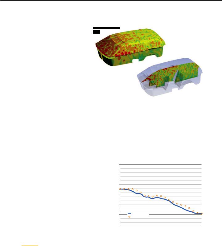
As validation for their results, the team collected SPL measurements from a wind tunnel using a microphone placed at the location of
the driver’s ear in a test vehicle. However, since wind tunnel measurements were of the total interior SPL, the team also needed information about the flanking noise in addition to the glazing noise. They could ignore the tire and mechanical system contributions to the SPL in this study since the test vehicle was stationary and not in operation. To account for the flanki 
noise, the team performed a separate wind tunnel test
with all glass surfaces shielded and then derived the total interior SPL. Overall there was excellent agreement between the simulation results and the experimental SPL data in terms of both trending and magnitude.
As an additional test, Corning analyzed what would happen if windshield and front side windows used a lighter-weight hybrid laminate, with the inner SLG layer replaced by a thinner layer of Gorilla® glass material. Though the simulations showed an acoustic penalty in terms of the glazing noise, the team judged the overall effect to be minimal since flanking noise is the dominant source at highway speeds. For both SLG–SLG and SLG–Gorilla glass laminate materials, using the smooth transition from the windshield to A-pillar compared to the standard under-flush transition
Cabin SPL at 1 kHz shown in overall 3D (top) and cross-section
(bottom) views, with red and orange representing the highest values
“The team estimated that it will reasonably be able to see a
30 to 50 percent improvement in the efficiency of its design and evaluation process, leading to a similar level of process cost savings.”
reduced the perceived cabin SPL for lower frequency (under 500 Hz) exterior noise.
At the end of the process, the Corning group had developed a model that provided powerful analysis for investigating full vehicle noise generation, transmission and propagation. With these initial results, the team estimated that it will reasonably be able to see a 30 to 50 percent improvement in the efficiency of its design and evaluation process, leading to a similar level of process cost savings.
Although different vehicle designs may show different levels of importance for the noise transmission paths, this general DAVA evaluation approach enables the designer to focus on the most critical glazing and optimize the design
120
100
(dB) |
80 |
|
|
Outer Ear |
|
|
|
60 |
|
|
|
at Driver’s |
|
|
|
40 |
|
|
|
SPL |
|
Model |
|
|
20 |
|
|
|
Wind Tunnel |
|
|
|
|
|
|
|
0100 |
1,000 |
10,000 |
References:
[1]J.D. Power. jdpower.com/cars/articles/jd-power- studies/vehicle-dependability-study-top-10-problems-3-year-old- vehicles (01/11/2018)
[2]Yu, C., Automotive Wind Noise Prediction using Deterministic Aero-Vibro-Acoustics Method, 23rd AIAA/CEAS Aeroacoustics Conference, AIAA AVIATION Forum, (AIAA 2017-3206).
© 2018 ANSYS, INC. |
ANSYS ADVANTAGE I 45 |

vk.com/club152685050 | vk.com/id446425943
OIL AND GAS
SURE FOOTING FOR
ONSHORE
DRILLING SITES
When the lifespan of working platforms made of boxes that raise oil workers’ equipment over waterlogged areas did not meet expectations, engineers turned to
ANSYS simulation. The time to develop new boxes has been reduced by 90 percent, and the lifespan is seven times greater than that of the previous design.
By Dewei Wang, Engineer, China National Petroleum Corporation,
Daqing Petroleum Equipment Group, Pumping Unit R&D, Daqing, China
46 I ANSYS ADVANTAGE |
ISSUE 1 | 2018 |
vk.com/club152685050 | vk.com/id446425943
Site preparation is a concern in many onshore drilling and production
projects. For sites in marshlands and regions near riverbanks there is the
added complexity of working in areas with standing water (up to a couple of
centimeters) surrounding the drill site. Water makes for unpleasant working
conditions, shortens equipment life and can have negative impact on the
surrounding environment. One solution is to build a foundation without a
large environmental impact.
To avoid this water issue, China National Petroleum Corporation (CNPC), the third largest oil company in the world, tried to shift the operating season from summer to winter, but this led to an unsustainable rise in heating costs. Another fix was to truck in tons
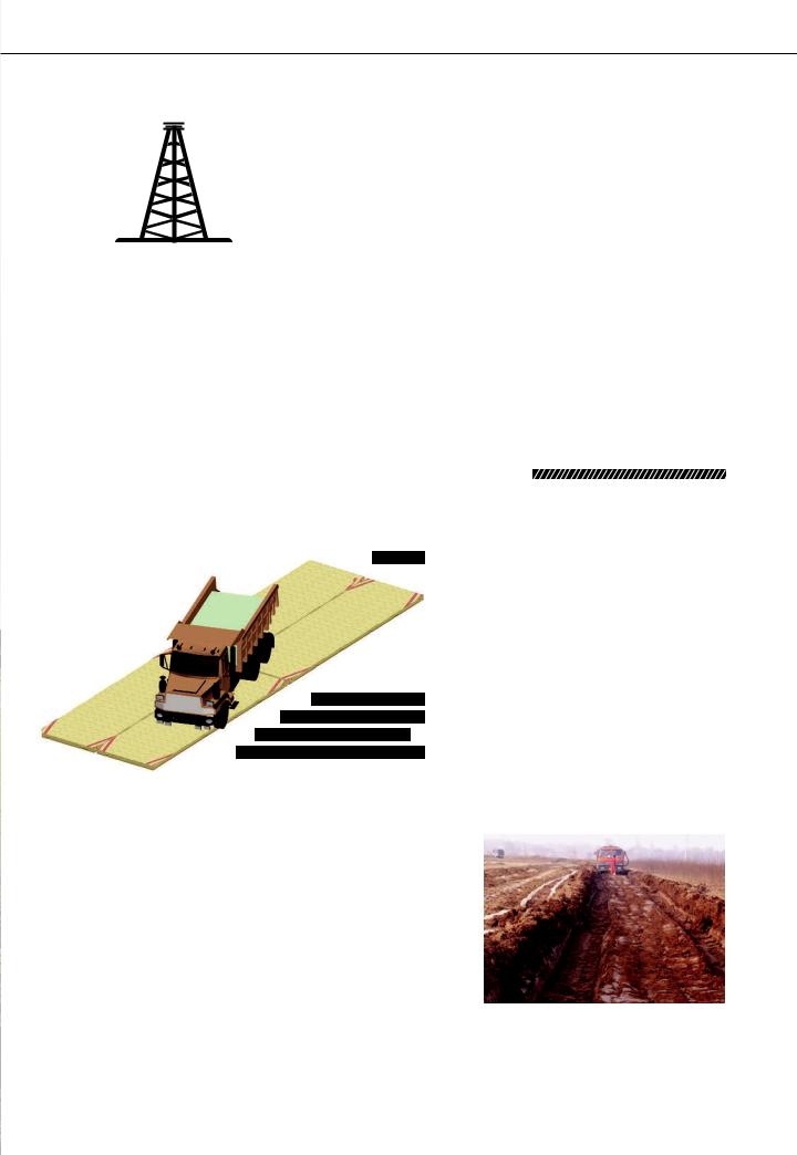
of dirt, which added significantly to the project costs, especially after environmental legislation was introduced in 2015 that requires all dirt that is transported into a site to be removed upon drilling completion. The current solution is to use base boxes composed of rigid steel
mesh and filled with dirt. When joined together, the boxes create a platform that allows workers and machinery to traverse the worksite while remaining above the water. Base boxes substantially reduce the amount of transported dirt that is required and therefore are superior to previous alternatives.
A typical field site has platform made from approximately 200 base boxes strung together into a single set that covers all of the necessary
working locations on a field. These boxes carry workers and trucks weighing 60 tons. When originally designed, these base boxes required several senior engineers to perform manual calculations, which
periments with numerous prototypes. The
 rocess overall required dozens of experienced workers and nearly four months to develop the boxes. The expected design life for the original base boxes was five years, but
  only lasted about two years because the
 strength was degrading faster than expected.
 that had a longer lifespan were required.
Mechanical structural simulation and
Workbench to design, test, iterate and
within ANSYS Workbench, the CNPC design  f the base box for an initial design that they then modify using shape optimization to meet the constraints of the available manufacturing processes. They perform a linear buckling analysis using the static and modal analysis module with
ANSYS Mechanical and determine the load limit for each box structure. The engineers optimize the design to obtain the best balance of strength, material and manufacturing costs. The thickness of the steel plate on the surface of the base box is the largest factor affecting the
strength and cost of the box. For each additional millimeter of thickness in the steel plate, the cost increases by 2.5 percent and the weight increases by 125 kg per square meter. The parametric capability within ANSYS software is used to optimize the final thickness of the steel top sheet.
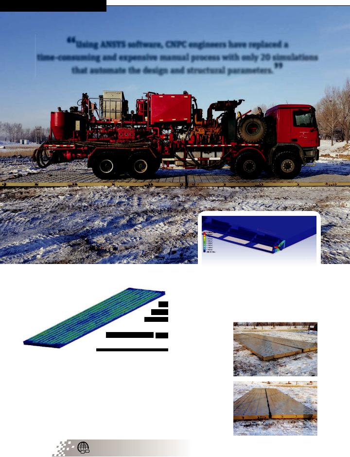
Using ANSYS software, CNPC engineers have replaced
a time-consuming and expensive manual process with only
20 simulations that automate the design and structural parameters. Structural designs are now completed in two weeks, the development cycle is reduced by nearly 90percent, and boxes are brought
© 2018 ANSYS, INC. |
ANSYS ADVANTAGE I 47 |
vk.com/club152685050 | vk.com/id446425943
Offshore Drilling Sites(continued)
“Using ANSYS software, CNPC engineers have replaced a time-consuming and expensive manual process with only 20 simulations that automate the design and structural parameters.”
Four base boxes under a piece of machinery
Simulation of hanging strength load determines if the structure can hold the intended weight.
market three months earlier than in the past. eight of a single base box is reduced by 40 percent.
boxes have an
 15 years and have
in earth procurement
 one year. The weight of decreased by 400 kg, which
reduces the amount of steel by over 70 tons at each well site. This means that related transportation
costs are also cut by 6.8 percent.
Integrated ANSYS solutions have helped CNPC save millions of dollars by enabling it to more fully analyze and optimize base boxes for the applicable well sites. Design cycles now take one-tenth the time of the old manual process, and the environmental impact has been substantially reduced by removing the need to truck thousands
of pounds of dirt in (and then out) for each well site.
Smart Strategies for Structural Simulations |
Base boxes |
ansys.com/structural-simulations |
|
48 I ANSYS ADVANTAGE |
ISSUE 1 | 2018 |
vk.com/club152685050 | vk.com/id446425943
OIL AND GAS
Designing
Modular
Wellheads
By Wen Chun Lee,
Product Design Engineer,
Singapore WEFIC Ocean
Technologies Pte. Ltd,
Singapore
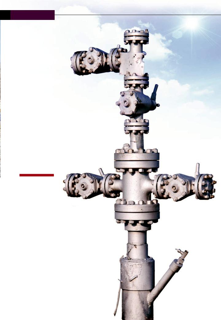
Using the Modular Wellhead System from Singapore WEFIC Ocean Technologies reduces installation time for downhole equipment in the oil and gas industry. Employing a multistage system that accommodates
different casing programs and working pressure, the system is easy to operate, safe and efficient. WEFIC engineers used ANSYS Mechanical to evaluate design alternatives for a key system component followed by physical testing to validate the finite element analysis results. This approach greatly reduced the number of test prototypes required, reducing development time by about 60 percent while ensuring reliability.
© 2018 ANSYS, INC. |
ANSYS ADVANTAGE I 49 |
vk.com/club152685050 | vk.com/id446425943
Designing Modular Wellheads (continued)
The wellhead sits at the surface of an oil or gas well and is the suspension point and pressure seal for the drill string, casing line and production tubing that are lowered into the hole at different
stages of the well’s lifecycle. Two types of equipment are attached to the top of the wellhead to control surface pressure: a blowout
preventer during drilling and a Christmas tree (valves, fittings and spools used
to control the flow out of the well) once drilling is completed. The wellhead’s internal bore contains shoulders upon which the casing and tubing hangers are
used to suspend casing strings and production tubing. While these shoulders
prevent downward movement of the casing and tubing hanger, a mechanism is also required to resist pressure from downhole that would otherwise force the casing and tubing hanger upward, possibly damaging the wellhead and causing seal leakage, which reduces holding pressure. The most common approach to addressing this issue involves fixing the hanger with tie-down screws. This approach requires considerable installation time because of the need to install and torque up the large quantity of tie-down screws.
“Using ANSYS technology made it possible to finalize the design in about 40 percent of the time required in the past.”
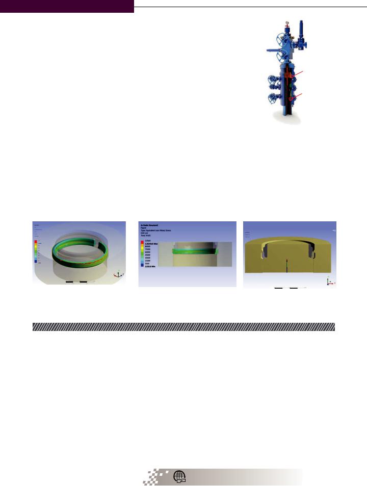
Stress experienced by lock ring under maximum loading
Another view of lock ring stress results
Reaction force to match the pressure rating of the wellhead was generated by applying displacement boundary to move the ring upward.
Singapore WEFIC Ocean Technologies Pte. Ltd. (WEFIC) provides high-tech petroleum equipment and technical services for the oil field engineering industry. The company’s Modular Wellhead (MW-I), which can
be used for both onshore and offshore application, reduces installation time with a lock ring that can be expanded radially until it sits in a groove in the wellhead. Installation is performed using a tool operated through the wellhead, riser and blowout preventer. This provides a significant reduction in installation time, which
reduces drilling expense. Using the company’s previous build-and- test methods, designing the lock ring for a new model wellhead would have required building and testing two to three prototypes, with about two months required for each. Engineers estimate that it would have taken about six months to design the lock ring this way. To design the lock ring for the new wellhead, the company used ANSYS Mechanical to get
the design very close to the final product in only 10 weeks with only
final adjustments required in the prototype phase. This made it possible to bring the product to market much faster.
Lock Ring Design Specifications
The lock ring must support upward forces resulting from pressure of 3,000 to 15,000 pounds per square inch (psi), depending upon the model of wellhead. The rings used on 3,000 and 5,000 psi wellheads interface with a single shoulder on the wellhead, while lock rings on the
Powering Global Prosperity ansys.com/prosperity
50 I ANSYS ADVANTAGE |
ISSUE 1 | 2018 |
vk.com/club152685050 | vk.com/id446425943
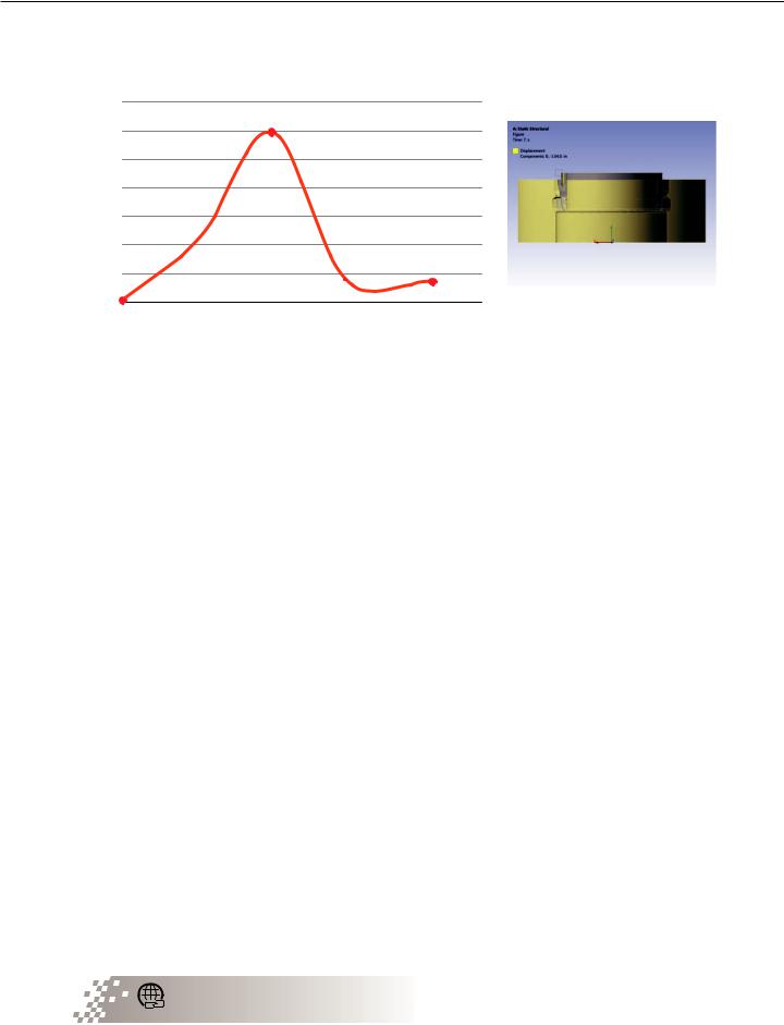
Lock Ring Expansion Force (lbf)
Expansion Force vs. Displacement
7,000
6,000
5,000
4,000
3,000
2,000 
1,000 
0
0.000 0.200 0.400 0.600 0.800 1.000 1.200 Displacement (in)
Maximum ring expansion force was retrieved by applying displacement boundary condition to expand the ring.
10,000 and 15,000 psi models act against multiple shoulders. Lock rings used in all these models must withstand upward forces equal to the pressure rating of the wellhead while respecting material yield limits within a specified margin of safety. The lock ring is split radially, and a rotating tool is used to expand the lock ring into a groove in the wall of the wellhead bore. The tool is operated by hand, so the amount of force required
to expand the ring is limited to approximately 200 foot pounds or less.
In the past, WEFIC engineers built and tested a physical prototype of each design iteration, which took about two months
per iteration. The reduction in oil prices in the past few years spurred the company to look for ways to increase the efficiency of its design processes. WEFIC worked with CAD-IT Consultants to create virtual prototypes with ANSYS simulation software that reduce the number of physical prototypes that need to be built
and tested. The company leveraged ANSYS Mechanical finite element analysis software to guide the
design of a lock ring for a 5,000-psi and 10,000-psi wellhead.
Engineers defined the material of the ring as alloy steel with more than 100,000 psi yield strength.
They needed to calculate both the force required to expand the ring and the stress throughout the ring when a force equal to the pressure rating of the wellhead is applied below the ring. They accomplished these goals by displacing the
ring so that it expands radially at the start of the simulation. When the ring is fully expanded, radial displacement ends and the
maximum force required to expand the ring is recorded. Next, another displacement boundary condition is used to move the ring upward. When the reaction force reaches the pressure rating of the wellhead, the simulation is stopped and the stress and deflection of the ring are evaluated.
Faster Market Deployment
The first design iteration provided acceptable expansion force, but the stress values were above
the design objectives. Engineers created additional design iterations by varying the values
Why Engineering Simulation is Critical for Breakthrough Energy Innovation ansys.com/energy-bei
for the thickness of the ring and the angle of the cross section of the outer diameter of the ring where it contacts the wellhead. Over a series of 10 iterations, they reduced the stress values to below the design specification, while reducing the expansion force and the weight of the locking ring.
Engineers then built and tested a prototype. The test results met all the design specifications and closely matched the simulation results. Using simulation, it took only two weeks to design the lock ring and another two months
to build and test the prototype. Using ANSYS technology made it possible to finalize the design in 10 weeks, which is about
40 percent of the time required in the past. Depending on the drilling conditions, well design and casing program, the WEFIC modular wellhead can save a substantial amount of drilling cost per well by reducing installation time.
This is only one example of how ANSYS tools have enabled WEFIC engineers to achieve a leaner product development process and deliver optimized and cost-effective solutions to the company’s customers
WEFIC is supported by ANSYS Channel Partner CAD-IT Consultants.
© 2018 ANSYS, INC. |
ANSYS ADVANTAGE I 51 |

vk.com/club152685050 | vk.com/id446425943
CONSTRUCTION
Turn Up the
Heat in a Rooftop
Heating Unit
In designing a new rooftop heating unit, AAON engineers needed to deliver higher airflow while maintaining the same footprint as an earlier design. The team used ANSYS computational
fluid dynamics (CFD) software to calculate airflow through the heat exchanger of the unit and iterate to a design that meets energy efficiency, airflow and heat transfer requirements. The use
of simulation in this project saved 60 to 80 hours of physical lab work compared to traditional design methods.
By Chait Johar,
Project Engineer,
AAON Inc.,
Tulsa, USA
52 I ANSYS ADVANTAGE |
ISSUE 1 | 2018 |