

ANSYS Polyflow
.pdfvk.com/club152685050 | vk.com/id446425943
AAON rooftop packaged units incorporate a tubular heat exchanger and air handling system for efficient heating of commercial and industrial buildings. To design the tubular heat exchangers used in rooftop heating units, engineers must maximize the transfer of heat from the hot gas flowing through the tubes to the air
flowing through the cabinet. This delivers a high level of energy efficiency. The unit must also withstand the service conditions of the environment while minimizing cost and size.
In the past, the design process involved building prototypes and performing physical measurements, such as testing the amount of heat that is transferred to the air flowing through the unit. Over the past few years, AAON has transitioned to using upfront simulation to optimize airflow and heat transfer prior to building physical prototypes. Simulation takes less time than building and testing a
prototype, and it provides more complete diagnostic information, enabling engineers to iterate to an optimized design at a faster pace. AAON engineers achieved physical space, air handling and thermal efficiency goals while saving 60 to 80 hours of manual lab work.
Heat Exchanger Design Challenge
In designing the new rooftop unit, engineers had to increase the air handling capacity while maintaining demanding levels of efficiency and the same footprint as the previous-generation product. The hot gas enters the heat exchanger, is divided into internal tubes and is then released out of the unit. Fresh air is brought in for the next combustion cycle to supply oxygen. The shell of the heat exchanger guides air driven by a fan over the tubes. Traditional design methods rely upon handbook formulas and engineering judgment that typically focus on the surface area through which heat is transferred by convection between the hot gas and cooler air flowing through the cabinet. The heat transfer capability and efficiency of the unit are largely dependent upon the flow of air through the heat exchanger tubes: The airflow should be uniformly distributed around the tubes carrying hot gas.
A key limitation of build-and-test methods is that they generally do not account for the flow geometry and thus must make assumptions for the
distribution of flow through the device. Due to these inherent inaccuracies in the traditional design process, soon after an initial concept design is
generated, the lab builds a prototype and puts it through its paces. This process takes about eight working days. At this stage, the
results are rarely good enough to meet product requirements, so the engineering team embarks on an iterative process of rebuilding and retesting the prototype. Engineers place
thermocouples on the exterior of the tubes, which provide an accurate measure of the thermal
performance of the prototype. But it is not practical to accurately measure the airflow
around the tubes, so these tests provide very little diagnostic information on how flow patterns are impacting
thermal performance.
ANSYS CFD Heat Transfer ansys.com/heat-transfer
© 2018 ANSYS, INC. |
ANSYS ADVANTAGE I 53 |
vk.com/club152685050 | vk.com/id446425943
Turn Up the Heat (continued)
Unit skeleton with only the heat exchanger tubes (8 tubes) and the fan
Simulation Now Drives Design Process
Over the past few years, AAON has transitioned to a new approach in which engineers use simulation to evaluate more design iterations in less time. Simulation provides more diagnostic information and iterates quickly to an optimized design. In designing the new RQA-B rooftop unit, engineers needed to move more heat and more air through a unit that occupies the same footprint but is taller than existing units. The new unit had to achieve an energy efficiency of 81 percent to be certified in all the regions in which it is being marketed.
Engineers created an initial design iteration and modeled the unit in ANSYS CFX computational fluid dynamics software. A master’s student at
“Simulation takes less time than building and testing a prototype and provides more complete diagnostic
information, enabling engineers to iterate to an
optimized design at a faster pace.”
Montana State University–Bozeman used physical testing to determine the axial, radial and tangential vector components of the airflow generated by different centrifugal fan sizes and speeds as a function of distance along the fan’s axis of rotation. These values were used as boundary conditions in the CFD model. The wall function approach was applied to model the boundary layer profile with a reduced cell count. Inflation layers were employed in the fluid domain near the tubes to provide a sufficiently fine mesh to accurately capture this region, where the flow experiences rapid changes in velocity, pressure and temperature. The placement of the first node in the mesh at the end of the tubes is particularly important. A nondimensional distance based on local cell fluid velocity called y+ ensures
Initial run showing air leaving the fan and exiting the cabinet. Much of the air did not pass through the heat exchanger tubes.
Baffles were added to divert the airflow and improve flow distribution.
54 I ANSYS ADVANTAGE |
ISSUE 1 | 2018 |
vk.com/club152685050 | vk.com/id446425943
that simulation accuracy in this area is acceptable. With the k-epsilon turbulence model that was used in this case, a y+ value of less than 100 is recommended. AAON engineers tweaked the mesh to keep y+ below 100.
AAON Reduces Physical Prototyping
The simulation results showed that the energy efficiency of the initial design was well below the required levels. AAON engineers also built a prototype of the initial design and used it to validate the simulation
results. Looking at the flow and temperature distribution in the cabinet and tubes, AAON engineers could see that a significant proportion of the air flowed past the heat exchanger tubes into the outlet without ever coming into contact with them. Based on these results, AAON engineers added baffles to the cabinet to redirect flow that had been bypassing the tubes. Using simulation, they were able to digitally explore different
baffle positions and geometries, along with different positions of the tubes relative to the sheet.
Each simulation run took 6 to 8 hours on a single core, so AAON engineers set up multiple runs when they left work in the evening. They are now using a computer with 4 cores, which has reduced the solution time to 1.5 to 2 hours. Guided by the flow simulation results, engineers rapidly iterated to a design that more efficiently routes air through the cabinet. The average air velocity through the heat exchanger tube faces increased by almost 25 percent, and the temperature into the outlet went up several degrees with the same flow rate through the cabinet. Engineers built a prototype of the optimized design, and the results closely matched the simulation results, providing an efficiency of 82 percent. AAON is currently ramping up production of the new rooftop unit and preparing to bring it to market. The AAON test lab manager estimated that, in this one application, simulation saved 60 to 80 hours of physical lab work, representing a substantial cost savings. Simulation also generated incremental revenues by bringing the product to market earlier than would have been possible using the build-and-test method.
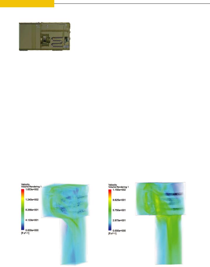
Flow velocity plot for initial design shows much of the air is flowing through the cabinet perimeter.
Flow velocity plot for final design with baffles added shows much more air is flowing through the tubes.
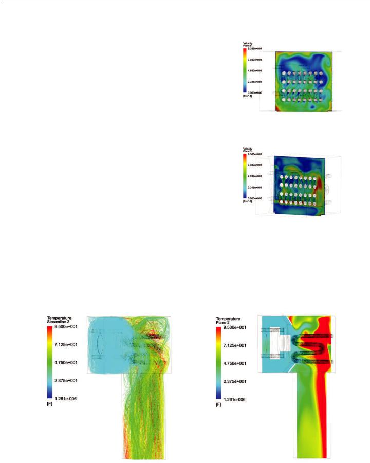
Streamlines depict the temperature changes through the cabinet.
Temperature on a cross section of the unit shows air temperature rising downstream of the cabinet.
© 2018 ANSYS, INC. |
ANSYS ADVANTAGE I 55 |
vk.com/club152685050 | vk.com/id446425943
NEWS
Simulationinthe
ANSYS 19 TAMES PRODUCT COMPLEXITY AND SPURS PRODUCTIVITY
ANSYS 19 empowers engineers to develop groundbreaking products, from autonomous vehicles to smarter devices to more electric aircraft, at an unprecedented pace. With enhancements across the entire industry-leading portfolio — from structures to fluids and from systems and semiconductors to electromagnetics — longtime users will notice dramatic improvements in time to solution, while new users can take advantage of state-of-the-art functionality. ANSYS 19 helps engineers manage complexity and enhance productivity, so that engineering and design teams achieve more accurate answers across the broadest range of applications — making simulation even more pervasive.
|
|
REAL-TIME DIGITAL EXPLORATION |
TEENS SEARCH FOR WAY TO IMPROVE |
newelectronics, February 2018 |
MAGNETIC RESONANCE IMAGES |
The commercial release of ANSYS Discovery Live |
CBC, October 2017 |
empowers millions of engineers around the world |
High-school students are using ANSYS simulation to |
to confidently simulate designs in real time quickly |
develop MRI technology for noninvasive blood testing. |
and more economically. Discovery Live is expanding |
By using MRI technology, the students can determine |
Pervasive Engineering Simulation — enabling |
the composition of blood without having to penetrate |
engineers to pose what-if questions upfront in the |
the skin. |
design process to rapidly explore thousands of design |
|
options and to receive immediate feedback. |
|
|
ADDITIVE MANUFACTURING PRESENTS |
|
AN OPPORTUNITY TO DISRUPT THE |
|
SUPPLY CHAIN |
|
Auto Tech Review, October 2017 |
|
ANSYS CEO Ajei Gopal provides insight into Pervasive |
|
Engineering Simulation, additive manufacturing and |
|
automotive megatrends in this interview. |
. . . . . . |
Simulation now pervades |
ANSYS ACQUIRES ADDITIVE |
“the entire product lifecycle. |
MANUFACTURING SIMULATION |
It is not just for the |
LEADER 3DSIM |
validation phase.” |
3DPrint.com, November 2017 |
—Dr. Ajei Gopal, |
ANSYS has acquired 3DSIM, a developer of powerful |
CEO, ANSYS |
simulation software for metal additive manufacturing. |
|
This has created a combined simulation solution |
|
that is now the industry’s only complete additive |
|
manufacturing simulation workflow. Additive |
|
manufacturing is the most rapidly growing and |
|
disruptive segment in the engineering market. |
|
. . . . . . |
|
56 I ANSYS ADVANTAGE
vk.com/club152685050 | vk.com/id446425943
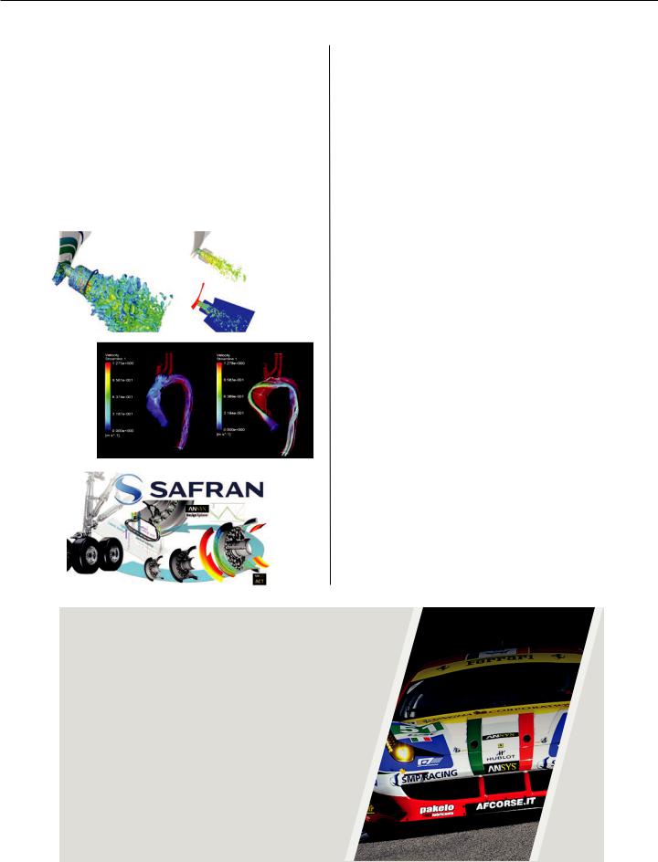
2018 ANSYS HALL OF FAME
DEMONSTRATES PERVASIVE
ENGINEERING SIMULATION
Every year, the ANSYS Hall of Fame Competition reveals the wide range of exciting uses for our software solutions from organizations around the world. From huge multinational corporations to small, creative startups, the commercial world employs engineering simulation to deliver reliable products to market quickly. And students, instructors and academic researchers leverage simulation to expand engineering knowledge.
Delphi
FTGM
Safran
CAE TURNS TO HIGH-PERFORMANCE COMPUTING
HPC Yearbook 2017-18, January 2018
In this interview, Wim Slagter of ANSYS explains the value of HPC technology for computer-aided engineering. As the barriers to HPC are reduced, more companies are able to leverage this technology.
“HPC is helping manufacturers cut costs and create new revenue streams because they can design completely new products they had not previously considered.”
—Wim Slagter,
Director of HPC and Cloud Alliances, ANSYS
. . . . .
ANSYS STARTUP PROGRAM GIVES AFFORDABLE CAE, HPC AND CLOUD TO THE MASSES
Engineering.com, October 2017
Rescale and ANSYS are spearheading a simulation and cloud computing program that enables startups to quickly and cost-effectively bring their innovative products to market.
. . . . .
BENCHMARK AN ANSYS MODEL FOR FREE
Digital Engineering, October 2017
To determine how your structural mechanics or fluid dynamics model performs on an HPC system (rather than your workstation), ANSYS has teamed with HPC partners. Through this program, you can benchmark your own model to determine the hardware solution that delivers the best return on your software and hardware investment.
ANSYS SUPPORTS FERRARI ENDURANCE RACING WINS
Today’s Motor Vehicles, December 2017
Securing its fifth WEC constructor’s title and twenty-fourth overall, Ferrari uses ANSYS computational fluid dynamics (CFD) solutions to maintain best-in-class endurance-oriented aerodynamic performance.
“ANSYS enables our team to quickly test multiple configurations between each lap and provides accurate insight — empowering our team to improve our speed and reliability in real time.”
—Ferdinando Cannizzo,
GT Technical Coordinator, Ferrari Competizioni
© 2018 ANSYS, INC. |
ANSYS ADVANTAGE I 57 |
vk.com/club152685050 | vk.com/id446425943
ANSYS, Inc.
Southpointe
2600 ANSYS Drive
Canonsburg, PA U.S.A. 15317
Send address corrections to AdvantageAddressChange@ansys.com

vk.com/club152685050 | vk.com/id446425943
ANSYS 19.1 — Технические требования к программно-аппаратным комплексам и лицензионная политика в области HPC
© ANSYS, Inc., ЗАО «КАДФЕМ Си-Ай-Эс», 2018

vk.com/club152685050 | vk.com/id446425943 |
|
|
Содержание |
|
|
1 |
Введение............................................................................................................................................................................. |
4 |
2 |
Порядок подбора комплектующих рабочих станций и серверов ................................................................................. |
4 |
3 |
Архитектура центральных процессоров серверов.......................................................................................................... |
4 |
4 |
Оперативная память .......................................................................................................................................................... |
5 |
5 |
Подсистема хранения данных .......................................................................................................................................... |
5 |
|
5.1. Стандартные решения ............................................................................................................................................... |
5 |
|
5.2. Параллельные файловые системы........................................................................................................................... |
5 |
|
5.3. Альтернативные решения для кластеров................................................................................................................ |
6 |
6 |
Использование сопроцессоров для ускорения расчетов............................................................................................... |
6 |
|
6.1. Использование профессиональных NVIDIA GPGPU ................................................................................................ |
6 |
|
6.2. Использование непрофессиональных GPGPU от NVIDIA........................................................................................ |
7 |
|
6.3. Использование Intel MIC для ускорения расчетов.................................................................................................. |
7 |
|
6.4. Использование профессиональных AMD GPU ........................................................................................................ |
7 |
|
6.5. Рекомендации для ANSYS Mechanical...................................................................................................................... |
7 |
|
6.6. Рекомендации для ANSYS Fluent .............................................................................................................................. |
8 |
7 |
Поддерживаемые GPU для вывода графики................................................................................................................... |
9 |
8 |
Интерконнект ..................................................................................................................................................................... |
9 |
|
8.1. Mellanox Infiniband................................................................................................................................................... |
10 |
|
8.2. Intel Omni-Path.......................................................................................................................................................... |
10 |
|
8.3. 10 GigE ....................................................................................................................................................................... |
10 |
9 |
Поддерживаемые реализации MPI и их ограничения ................................................................................................. |
10 |
10 Операционные системы серверов ............................................................................................................................... |
10 |
|
|
10.1. Дистрибутивы Windows......................................................................................................................................... |
11 |
|
10.2. Особенности настройки операционных систем Windows.................................................................................. |
11 |
|
10.3. Дистрибутивы Linux ............................................................................................................................................... |
13 |
11 Менеджер и сервер лицензий...................................................................................................................................... |
13 |
|
|
11.1. Основные принципы.............................................................................................................................................. |
13 |
|
11.2. Порты для работы менеджера лицензий ............................................................................................................ |
14 |
|
11.3. Настройка клиентской стороны............................................................................................................................ |
15 |
|
11.4. Проверка открытости портов ................................................................................................................................ |
15 |
|
11.5. Работы старых версий ANSYS после обновления................................................................................................ |
18 |
12 Типовая конфигурация узлов кластера........................................................................................................................ |
18 |
|
13 Система планирования очереди задач........................................................................................................................ |
19 |
|
|
13.1. Общие сведения..................................................................................................................................................... |
19 |
|
13.2. ANSYS Remote Solve Manager ................................................................................................................................ |
19 |
|
13.3. ANSYS RSM Cluster .................................................................................................................................................. |
20 |
2

vk.com/club152685050 | vk.com/id446425943 |
|
14 Работа с удаленными ресурсами и виртуализация .................................................................................................... |
20 |
14.1. Средства доставки удаленных рабочих столов................................................................................................... |
20 |
14.2. Средства организации виртуализованных рабочих мест................................................................................... |
21 |
15 Лицензионная политика для коммерческих продуктов ANSYS ................................................................................. |
21 |
15.1. Встроенные HPC возможности решателей .......................................................................................................... |
22 |
15.2. Лицензии ANSYS HPC (Workgroup)........................................................................................................................ |
22 |
15.3. Лицензии ANSYS HPC Pack ..................................................................................................................................... |
22 |
15.4. Лицензирование использования GPGPU для ускорения расчетов. .................................................................. |
23 |
15.5. Лицензии ANSYS HPC Parametric Pack .................................................................................................................. |
23 |
15.6. Лицензирование ANSYS LS-DYNA.......................................................................................................................... |
24 |
15.7. Optimetrics + DSO.................................................................................................................................................... |
24 |
16 Лицензионная политика для академических продуктов ........................................................................................... |
24 |
17 Документация ANSYS ..................................................................................................................................................... |
24 |
Заключение.......................................................................................................................................................................... |
26 |
3

vk.com/club152685050 | vk.com/id446425943
1 Введение
Материалы данной брошюры актуальны для версии программных продуктов ANSYS 19.1 и ANSYS Electromagnetics Suite 19.1 на 20 января 2018 года. Источники информации – опыт компании ЗАО «КАДФЕМ Си-Ай-Эс» и
официальная документация ANSYS (https://www.ansys.com/Solutions/Solutions-by-Role/IT-Professionals/Platform- Support).
2 Порядок подбора комплектующих рабочих станций и серверов
Существует четкая последовательность создания конфигурации рабочих станций, серверов или узлов кластера для выполнения расчетов. Шаги, описываемые далее следует выполнять строго по порядку.
1.Использовать центральные процессоры на основе архитектуры, выпущенной не позднее за 1 год до момента закупки. Желательно использовать самую новую процессорную архитектуру. Это позволит раскрыть все возможности актуальной версии ПО.
2.Из процессоров выбранной архитектуры отобрать модели с максимальной тактовой частотой – тактовая частота гарантирует более быструю работу ПО. При этом надо помнить, какой лицензионное покрытие вы имеете (сколько ядер на расчет можно задействовать). Возможно оптимальным решением будет не самый высокочастотный процессор, а следующий за ним.
3.После окончательного выбора, сбалансированного по процессорам решения (тактовая частота/количество ядер), обеспечите их необходимым количеством оперативной памяти. В среднем рекомендуется использовать 4 – 8 Гб памяти на ядро. Рекомендуется набрать объем памяти как можно меньшим количеством модулей. При этом надо помнить, о количестве каналов работы с памятью в процессоре – все они должны быть задействованы. Так, например, не рекомендуется оснащать процессор с 4-х канальным контроллером памяти 2-мя или 3-мя планками оперативной памяти. Такая конфигурация не сможет использовать всю вычислительную мощность процессора.
4.Следующим шагом следует оптимизировать дисковую подсистему. Рекомендуется использовать твердотельные накопители. Больше всего они влияют на задачи механики, затем идут задачи электромагнетизма и радиофизики, и меньше всего к дисковой подсистеме чувствительна гидродинамика. Важно, чтобы на быстром дисковом массиве располагалась в первую очередь рабочая папка, а не директории, содержащие код решателя и операционной системы. В некоторых, редких случаях, для задачи механики можно делать виртуальные диски из оперативной памяти (RAM Disk) – тогда необходимо оснастить компьютер двойным или тройным объемом оперативной памяти.
5.Только после оптимизации конфигурации системы по центральному процессору, оперативной памяти и дисковой подсистеме следует приходит к выбору математических сопроцессоров NVIDIA и Intel. В случае NVIDIA необходимо выбирать решения с максимальной производительностью в операциях с двойной точностью и с максимальным объемом памяти.
6.В качестве графического процессора для вывода графики рекомендуется использовать профессиональные решения NVIDIA и AMD. Это существенно увеличит скорость работы графической подсистемы сеточных генераторов и программных продуктов на основе геометрического ядра SpaceClaim.
3 Архитектура центральных процессоров серверов
ПО ANSYS и ANSYS Electromagnetics Suite работает только на серверах стандартной архитектуры Intel-AMD x86-64.
4