

ANSYS Polyflow
.pdfvk.com/club152685050 | vk.com/id446425943
ANSYS also offers solutions for other sensor technologies, such as ultrasound, which is primarily used for parking assistance.
Optimizing Semiconductor Performance
ANSYS also enables the simulation of the semiconductor components that underlie radar systems and
support signal processing. By leveraging the ANSYS semiconductor product suite, these semiconductors can be analyzed along with the surrounding circuitry in a combined chip–package–system design environment.
Semiconductors support much of the functionality of
autonomous vehicles, yet
the sheer number of electronics required can be the source of significant
performance issues. Power loss, electrostatic discharge, electromagnetic interference, and thermal
and structural stresses can all negatively impact product reliability and integrity. For example, a 25 C temperature increase typically leads to a 3-times to 5-times degradation in the expected lifetime of electronic devices.
ANSYS offers a number of specialized solutions, including ANSYS RedHawk 3DIC and PowerArtist, that can optimize the design of
integrated circuits. These solutions help engineers manage electronics density and make intelligent trade-offs among product size, thermal build-up and overall product performance. The product development team can launch vehicles with the confidence that semiconductors will perform as expected in realworld operating environments.
Electronics Reliability: Building Hardware to Last
Advanced electronics hardware is one of the most critical components of any autonomous vehicle, supporting such key capabilities as communication, image and data capture, system control, artificial intelligence,
“As companies race to solve the remaining
engineering challenges and launch innovative,
yet practical, autonomous vehicles, simulation is a competitive imperative.”
© 2018 ANSYS, INC. |
ANSYS ADVANTAGE I 13 |

vk.com/club152685050 | vk.com/id446425943
Navigating Toward Full Autonomy (continued)
<SM1>
|
|
|
|
Enabled |
|
|
|
|
|
|
|
|
|
|
<SM2> |
|
|
|
Active |
|
|
|
|
|
|
|
|
|
<SM3> |
|
|
|
On |
|
|
|
|
|
|
|
|
|
|
StdbyCondition |
|
|
|
|
Local_CruiseSpeed |
2 |
|
1 |
Standby |
Brake > PedalsMin |
|
|
|
|
|
||||
|
|
|
|
|
|
||
|
CruiseRegulation |
ThrottleCmd |
|
|
|
|
|
|
Speed |
|
|
STDBY |
CruiseState |
1 |
Interrupt |
|
|
|
|
|
|
||
On |
|
|
|
1 |
|
INT |
CruiseState |
|
|
|
|
|
|||
ON |
CruiseState |
|
|
|
|
||
|
not StdbyCondition |
|
|
|
|||
1 |
|
|
|
|
1 |
|
|
|
|
|
|
|
|
||
Off |
|
|
|
|
|
Resume |
|
|
|
|
|
|
|
|
|
1 |
Accel > PedalsMin |
|
1 |
|
|
|
|
Off |
Speed < SpeedMin |
|
|
StdbyCondition |
|
|
|
|
|
|
|
|
|
|
|
|
Speed > SpeedMax |
|
|
|
|
|
|
DATA |
|
|
|
|
|
Local_CruiseSpeed |
|
|
Set |
|
|
|
|
|
|
|
|
QuickAccel |
|
|
|
|
|
|
|
|
|
CruiseSpeedMgt |
|
CruiseSpeed |
|
|
|
QuickDecel |
|
|
|
|
|
|
|
Speed |
|
|
|
|
|
product development, SCADE solutions are designed for easy integration with third-party neural network and machine learning software.
In addition to improving the reliability of software code, ANSYS SCADE delivers significant improvements in development time and costs, as compared to manually based code-generation methods. Some customers report that software development time
has been reduced by a factor of three by using ANSYS SCADE, as compared to a process without automatic code generation and verification.
Functional Safety: An Automated Approach
No matter how rigorous the upfront engineering process, any electronic system can fail in the field. Unfortunately, this holds true for autonomous vehicles, where system-level failures can be catastrophic. Engineers need to build in a high degree of functional safety, which ensures that the overall system can respond appropriately should one component fail.
Because autonomous vehicles are composed of a multitude of mechanical parts, electronics, hardware and software, the process of functional safety analysis can be enormously complicated. Manual verification processes can be not only tedious and expensive, but are inherently prone to human error.
To address this problem, ANSYS offers the medini analyze solution family, which automates functional safety analysis and seamlessly integrates this critical activity into overall product development. Instead of working with assumptions about how the vehicle will perform in the event of a functional failure, engineers can evaluate potential failure modes using a fact-based method. They can then design a system-level response that mitigates the effects of that failure mode and protects human safety.
Winning the Race
Today the question is not “Will we see fully autonomous vehicles transform multiple industries in the near future?” but “Who will be first?”
As companies race to solve the remaining engineering challenges and launch innovative, yet practical, autonomous vehicles, simulation is a competitive imperative. ANSYS is building the industry’s only comprehensive solution for simulating the performance of autonomous vehicles over the billions of miles they must be driven, flown or maneuvered.
Whether you are developing an entire vehicle or a component, simulation is relevant to your engineering challenges. ANSYS offers a single, configurable platform for validating vehicle performance against safety requirements. Its open nature integrates autonomous vehicle design into an ecosystem that includes, but is not limited to, high-fidelity physics studies, diverse sensor models, vehicle dynamics, world scenarios, embedded software code development, connectivity optimization, data analytics and functional safety analysis. Simulation software from ANSYS can be configured to a given development environment, hardware-in-the-loop requirements and the vehicle’s unique architecture.
Whatever challenge you are facing related to vehicle autonomy, we hope that you will find inspiration in this issue of ANSYS Advantage, as we profile some of the ground-breaking simulation work being accomplished by customers worldwide who are currently focused on winning this exciting race
References:
[1]USA Today. usatoday.com/story/money/cars/2017/10/06/ nhtsa-2016-deadly-crashes/739842001/ (02/18/2018)
[2]NPR. npr.org/2016/10/20/498406570/tech-human-errors- drive-growing-death-toll-in-auto-crashes (02/18/2018)
[3]RAND Corporation. rand.org/content/dam/rand/pubs/ research_reports/RR1400/RR1478/RAND_RR1478.pdf (02/18/2018)
[4]Waymo. waymo.com/safetyreport/ (02/18/2018)
14 I ANSYS ADVANTAGE |
ISSUE 1 | 2018 |

vk.com/club152685050 | vk.com/id446425943
SOFTWARE AND ALGORITHM DEVELOPMENT
It would be impossible to program a computer to handle every possible driving scenario, so today’s autonomous driving systems feature programs that learn and think like human beings to make the right decision for almost every situation. But how can these programs be verified for safety? The answer is by carefully designing an embedded software architecture that maximizes safety and a simulation platform that bombards autonomous driving software with billions of difficult driving cases to quickly identify its weaknesses.
By Michael Wagner, Chief Executive Officer,
Edge Case Research, Pittsburgh, USA
Bernard Dion, Chief Technical Officer–Systems,
ANSYS
Verifying and validating the ability of autonomous driving systems to operate in a complex environment presents an enormous challenge.
Delivering an autonomous driving system, one that has the ability to understand every conceivable driving situation and make judgments to ensure the safety of
vehicle occupants and pedestrians, is a complex and demanding
task. For example, consider the challenge of developing rules for identifying any imaginable
pedestrian, vehicle or other object that could appear on a city street. Conventional requirements-driven programming methods are not capable of mastering the huge number of potential situations that could occur on today’s roads and highways.
Hands-off autonomous driving systems rely upon deep learning algorithms that can be trained to develop human-like capabilities to recognize patterns without having to be exposed to every possible situation that could arise on a trip to the grocery store. These systems lack the defined detailed requirements
© 2018 ANSYS, INC. |
ANSYS ADVANTAGE I 15 |
vk.com/club152685050 | vk.com/id446425943
Drive Safely (continued)
CONTROLLER
STEERING
CONTROL
LATERAL
DYNAMICS
CAMERA
BRAKE
LONGITUDINAL CONTROL
DYNAMICS
RADAR
ENGINE
CONTROL
Conventional software cannot do the job, so machine learning and deep learning are at the heart of the latest autonomous driving software.
and architecture that are used to validate conventional safetycritical software. Road testing is not a practical verification
method because billions of miles would be required to demonstrate safety and reliability. The ANSYS ADAS/autonomous vehicle open simulation platform integrates physics, electronics, embedded systems and software simulation to accurately simulate complete autonomous driving systems.
By linking the ANSYS simulation platform and ANSYS SCADE model-based development tools with Switchboard™ automated robustness testing technology from Edge Case Research (ECR), together with ANSYS medini functional safety analysis, it is possible
to achieve end-to-end safety in autonomous driving systems, including those that use deep learning.
From ADAS to Autonomous Driving
Advanced driver assistance systems (ADAS) are increasingly being used in today’s automobiles to alert drivers to potential problems or even to take control of the vehicle to avoid a collision.
These safety systems are normally validated using the system and embedded software lifecycle V-model defined in ISO 26262. Using the V-model, developers carefully define the detailed requirements and architecture of the system and then methodically verify the ability of the system
to meet each of the requirements. The ANSYS SCADE Suite complete end-to-end model-based system engineering (MBSE) solution is used in the development of safety-related
systems for leading automobile manufacturers.
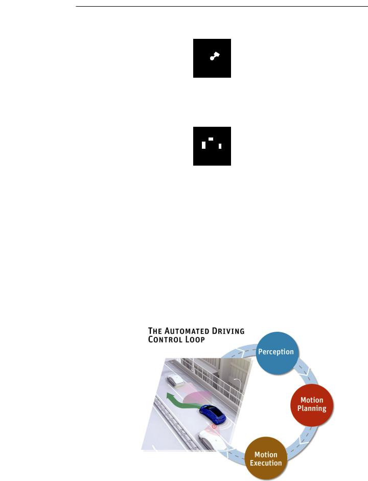
Developing a fully autonomous driving system is much more sophisticated, and must be based on a combination of machine learning/deep learning and control logic to implement the full autonomous vehicle control loop. The control loop is composed of perception (what the car observes), motion planning (what behavior the car is planning)
and motion execution (how the car will complete the plan). This control loop is executed in a cyclic fashion so that the vehicle can respond to constant changes in the environment. But autonomous driving systems based on machine learning can only be released
to the public after developers have demonstrated their ability to achieve extremely high levels of safety. Road testing is clearly an essential part of the vehicle development process, but it is not the answer to safety validation. The problem is that road testing primarily consists of routine occurrences that are not difficult for human or autonomous drivers. Billions of miles of road testing would be required to validate
16 I ANSYS ADVANTAGE |
ISSUE 1 | 2018 |
vk.com/club152685050 | vk.com/id446425943
“Hands-off autonomous driving systems rely
upon deep learning algorithms that can be trained to recognize patterns without having to be exposed
to every possible situation.”
safety, and, even then, a failure or a change of code would potentially require starting over from zero.
Overcoming the Safety
Verification Challenge
The ANSYS ADAS/autonomous vehicle open simulation platform can test many more scenarios
in a fraction of the time and cost required for road testing by incorporating:
•Simulation of driving scenarios, including modeling of both
the virtual world in which the autonomous car is operating and the virtual vehicle itself with accurate sensor simulation (radar, lidar, cameras, GPS, etc.) as well as vehicle dynamics.
•ISO 26262 qualified model-based development tools for control and human machine interface (HMI) software.
•Optimization of the signal integrity, thermal, structural and electromagnetic reliability of
semiconductors and electronics systems.
The integration of all physics, embedded systems, software simulation and code generation enables developers of autonomous systems to accurately simulate
Drive Scenario Model
Creates a model of the virtual world and animates motions of the test car and other objects in a test drive
·3D road and landscape model
·3D models of stationary and moving objects
·Object sensory attributes (e.g., radar reflectivity)
·Object motion definition
·Motion simulation in time domain
Vehicle Dynamics Model
Computes position, velocity and orientation of test vehicle
·Vehicle mechanical model
·Sub-models for vehicle attributes
Vehicle Component Model
Uses actuator inputs and computes response of vehicle subsystems such as brakes and steering
·3D models of vehicle components
·Detailed multiphysics simulation
the complete automated driving control loop on a single platform. The drive scenario model animates the motion of the test car and other vehicles and objects in a test drive. Sensor models observe the surroundings in the
Sensor Models
“Observe” the surroundings in the virtual world of the drive scenario model and output processed sensor signals
· Sensing simulation |
· Signal processing |
|
|
|
|
PMD |
|
Cameras |
|
|
|
Radar |
|
Lidar |
|
|
|
V2X |
|
GPS |
|
|
|
Ultrasonic Sensors
Signal Processing & Sensor Fusion
Identifies objects and driving conditions from sensor data
Control Algorithms and HMI
Makes main control decisions; displays critical information and decisions to the driver
·Software lifecycle, model-based development, software testing, code generation
·ISO26262, functional safety
Simulation of the automated driving control loop
HiL, Rapid Prototyping |
Virtual World |
|
|
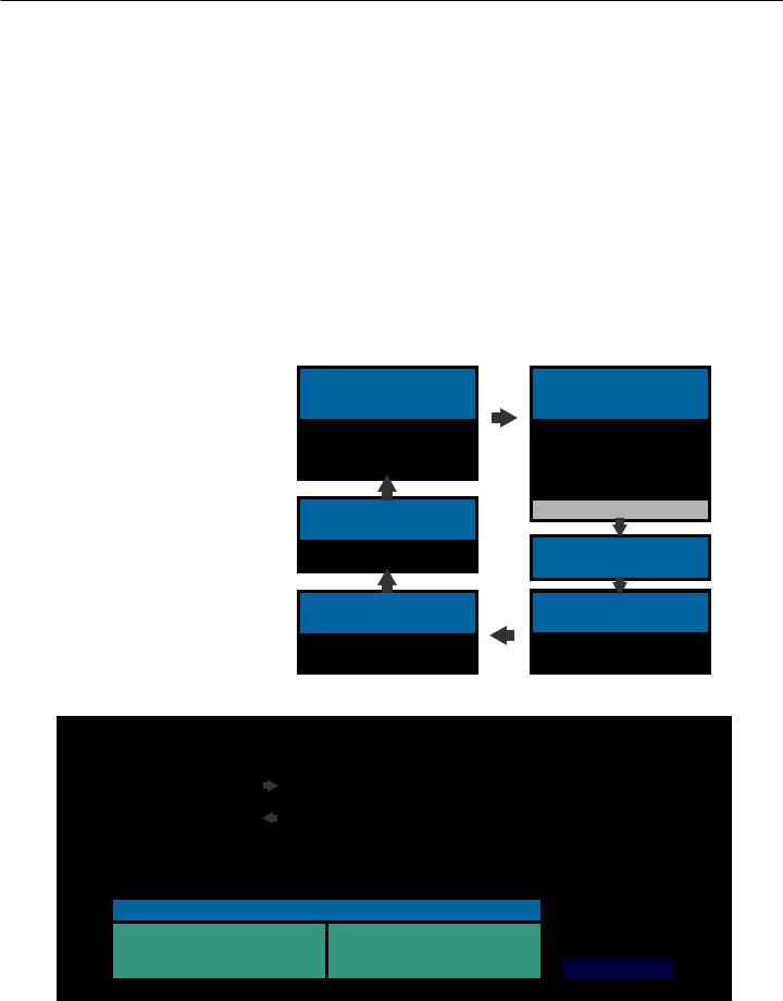
CLOSED-LOOP SIMULATION
Environment |
|
|
Sensor Models: Radar, Camera, Lidar, Ultrasound, Speed, GPS, V2X... |
|
Vehicle |
||||||||||
Traffic Objects |
|
|
|
|
|
AV Software |
|
|
|
|
|
|
|
||
& Behavior |
|
|
Perception |
|
Motion Planning |
|
|
Motion Execution |
|
Virtual |
|||||
|
|
|
|
|
|
||||||||||
|
|
|
|
|
|
|
|
|
|
|
|
|
|
|
|
Motion & Rendering |
|
|
|
|
Vehicle Components & Vehicle Dynamics |
|
|
|
|
|
|||||
|
|
|
|
|
|
|
|
|
|
||||||
|
|
|
|
DATA |
|
|
|
|
|
|
|
VALIDATION |
|
||
|
|
|
|
|
|
|
|
|
|
|
|
||||
|
|
Models: World, Vehicle & Software |
|
|
|
|
|
|
|||||||
|
|
|
|
|
|
|
|
||||||||
|
|
|
|
|
Simulation |
|
|||||||||
|
|
|
|
|
|
|
|
|
|
|
|
|
Results |
|
|
|
|
|
|
|
|
|
|
|
|
|
|
|
|
|
|
|
Physical: |
|
|
|
|
|
Simulation: |
|
|
|
Requirements |
|
|||
|
World & Sensor |
|
|
|
|
|
World & Vehicle |
|
|
|
|
|
|
||
|
|
|
|
|
|
|
|
|
|
|
|||||
Scenarios
Client Network
ANSYS autonomous vehicle simulation architecture
© 2018 ANSYS, INC. |
ANSYS ADVANTAGE I 17 |
vk.com/club152685050 | vk.com/id446425943
Drive Safely (continued)
Unverified Inputs |
|
|
|
|
|
|
|
|
||
|
|
|
Primary |
|
|
|
Safing Gate |
|
|
Verified |
|
|
|
Algorithm |
|
|
|
|
|
|
Primary |
|
|
|
|
|
|
|
|
|
|
Output |
Verified Inputs |
|
|
|
|
|
|
|
|
|
Verified |
|
|
|
|
|
|
|
|
|||
|
|
|
|
|||||||
|
|
|
|
|
|
|
|
|
|
Safing |
|
|
|
|
|
|
|
Safing |
|
|
Output |
|
|
|
|
|
|
|
|
|
|
|
|
|
|
|
|
|
|
Channel |
|
|
|
|
|
|
|
|
|
|
Algorithm |
|
|
|
|
|
|
|
|
|
|
|
|
|
|
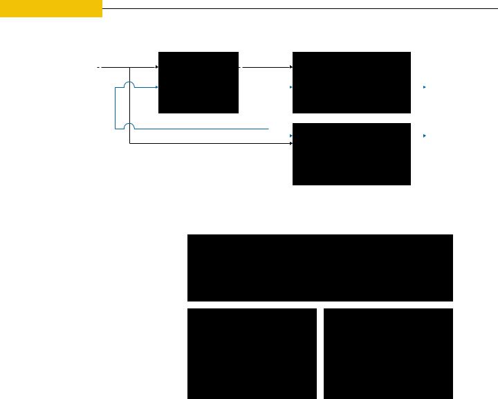
The primary channel produces a long-duration mission with no defined end state, while the safing channel produces a short-duration mission that ends in a safe state.
virtual world and output sensor signals. Signal processing models and deep learning identify objects and driving conditions from sensor data. Control algorithms make control decisions, generate actuator inputs, and display information and decisions to
the passenger/operator. Vehicle component models use actuator inputs and compute the response of vehicle subsystems such as steering and braking. The vehicle dynamics model computes position, velocity and orientation of the test vehicle.
Safe Architecture for Safe Vehicles
While simulation is far faster and more efficient than road testing, it does not on its own answer the question of how to verify the safety of the complex autonomy algorithms used for perception, motion planning and execution functions.
To do this, first engineers must break down the overall autonomous vehicle software architecture into a meaningful set of components based on perception, planning and execution. Next, they must design an architecture that will guarantee safety for each of these components. This architecture
is based on a DOER-CHECKER principle.
|
Unverified Inputs (FA) |
|
Unverified |
|
|
Verified |
||
|
|
|
|
|||||
|
|
|
|
|
|
|||
|
Verified Inputs (FS) |
Algorithm |
Output |
|
Safing Gate |
Output |
||
|
(FA) |
(FA) |
|
(FS) |
(FS) |
|||
|
|
|
|
|
|
|
|
|
|
|
|
|
|
|
|
|
|
|
|
|
|
|
|
|
|
|
Source: Carnegie Mellon University
The algorithm (the “DOER”) can fail arbitrarily (FA) meaning it can do wrong things in the worst possible way.
The safing algorithm for the planning phase
The detailed architecture is composed of a primary algorithm (DOER) that may be extremely complex, undergo frequent updates and be difficult to verify. This primary algorithm is paired with a corresponding safing gate (CHECKER) that verifies that the outputs of the primary
algorithm are correct. If the safing gate detects a problem, a safing channel algorithm takes control. This can be the basis for the twochannel architecture developed by members of the ECR team while at Carnegie Mellon University (see diagram). This architecture comprises a primary channel that produces a long-duration mission and a safing channel that
The safing gate (the “CHECKER”) turns the algorithm into a fail silent (FS) component, only producing correct data or shutting down.
produces a short-duration mission, such as pulling the car to the side of the road.
Using this architecture, the plan can be checked for safety during the planning phase. The primary algorithm need not satisfy safety objectives at the highest level (ASIL D in ISO 26262); rather, this responsibility is allocated
to the safing gate. What makes this possible is that the detailed safety requirements of the safing gates can be established so that their implementation meets the objectives of ISO 26262 at ASIL D. This is depicted by the example shown, in which the car is going to stop because a double-parked car has been detected.
18 I ANSYS ADVANTAGE |
ISSUE 1 | 2018 |
vk.com/club152685050 | vk.com/id446425943
Automated Robustness Testing Identifies and Diagnoses Failures for Perception
Assuring the safety of perception is more complex; it is not possible to create a safing gate to check that perception outputs are correct and safe. Therefore, safety of perception must be validated using different techniques. ECR Switchboard addresses this challenge (and some others) by providing automated robustness testing to find failures.
What is needed to prove perception safety is large-scale exposure to the difficult cases that can challenge autonomous driving systems (and often human drivers). ECR Switchboard uses
a novel algorithm to cut through the potentially endless number of possible tests to quickly find test cases that cause software to fail and understand why the failure occurred. It sifts through the highdimensional input space to identify exceptional queries that are informative for testing the model. It bombards the automated driving system with a mixed stream of nominal and exceptional inputs until a failure occurs. The failures are then diagnosed by generalizing a single fault-triggering input to produce a set of inputs that serve as hints in implicating field-value assignments in triggering the failure. This approach is highly effective at finding edge cases that cause system failures.
Perhaps the greatest challenge remaining in the large-scale deployment of autonomous driving systems is testing and debugging machine learning and deep learning algorithms that work without defined requirements and design to ensure their robustness and safety. ANSYS has leveraged its vast experience in multiple physics simulation and simulating safety-critical embedded software to deliver a complete automatic
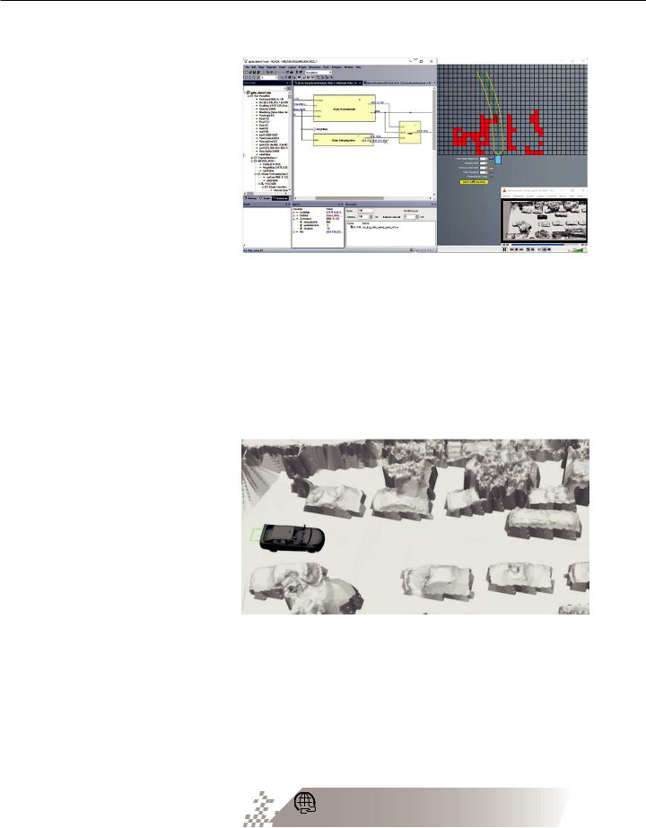
ECR Switchboard identifies perception failure: strong detection becomes extremely weak after barely perceptible environmental changes. The deep-learning algorithm can be augmented under test using any failures the Switchboard finds.
“The ANSYS/ECR partnership can deliver a complete solution to verify and validate the safety of the most advanced autonomous driving systems.”
ECR switchboard finds a path planning failure
driving simulation platform that includes the world’s only ISO 26262–compliant code generator. This platform is now integrated with the ECR Switchboard robustness testing platform, which runs huge numbers of simulation scenarios while biasing toward
difficult scenarios to mitigate residual safety validation risk. This partnership can deliver a complete solution to verify and validate
the safety of the most advanced autonomous driving systems.
Analysis and Development of Safety-Critical Embedded Systems: The Need for an Integrated Toolkit ansys.com/safety-critical
© 2018 ANSYS, INC. |
ANSYS ADVANTAGE I 19 |

As automotive electronics’ role transitions from entertaining the driver to assisting the driver, to taking full control of the vehicle, its reliability is coming under increasing scrutiny. Critical automotive electronic systems need to last more than 10 years, often under hostile underhood
environments where temperatures can range up to 150 C. ANSYS simulation tools enable engineers to simulate, debug and optimize proposed electronic systems designs with respect to issues that might cause an automated driving system to fail. Simulation makes it possible to design robust and efficient electronic systems that meet demanding reliability requirements for autonomous driving applications. This article will focus on the varied aspects of reliability and chip–package–system (CPS) simulations that enable package/system-aware integrated circuit (IC) design and IC-aware package/system design.
20 I ANSYS ADVANTAGE |
ISSUE 1 | 2018 |

vk.com/club152685050 | vk.com/id446425943
Autonomous Driving Reliability Challenges
Today’s drivers increasingly depend upon electronic systems to ensure safety. For example, nearly every car uses an antilock braking system to reduce stopping distance in slippery conditions. The recent proliferation of advanced driver assistance systems (ADAS) capabilities, such as applying the brakes automatically if the vehicle ahead stops or slows suddenly, have further increased the importance of electronics in vehicle safety. Of course, the emergence of autonomous driving systems that understand every conceivable driving situation and make judgments
to ensure the safety of vehicle occupants and pedestrians will further increase the dependence of driver, passenger and
pedestrian safety on automotive electronics.
Many current automotive electronics applications reside on semiconductors based on older process nodes that are relatively easy to validate from a reliability standpoint because of their large feature size and the experience of designers. However, the sensors used in ADAS and autonomous driving technology generate
“Simulation makes it possible to design robust and efficient electronic systems that meet demanding reliability requirements for autonomous driving applications.”
huge amounts of data (40 gigabytes per hour is not unusual) that must be processed at blinding speeds and with low latency. These applications require vast increases in computing power that can be satisfied only by leading-edge semiconductor processes with much smaller feature sizes that are just now reaching the market.
The new generation of integrated circuits, designed in advanced process nodes, pack more transistors into a smaller footprint to deliver the highest possible levels of computing performance. These ICs operate at much lower supply voltages, making them more susceptible to power and signal noise coupling. Another
challenge is that in many cases these semiconductors will need to operate in underhood environments where ambient temperatures can reach up to 135 C, which makes them more susceptible to thermal-induced failures. This thermal challenge is intensified because electronic components in many automotive applications are exposed to water and dirt, so they must be sealed against the elements. This increases the difficulty of providing adequate cooling.
© 2018 ANSYS, INC. |
ANSYS ADVANTAGE I 21 |
vk.com/club152685050 | vk.com/id446425943
Safe Travels (continued)
“The ability to identify and troubleshoot reliability issues with simulation makes it possible to achieve substantial reductions in time to market and to improve reliability.”
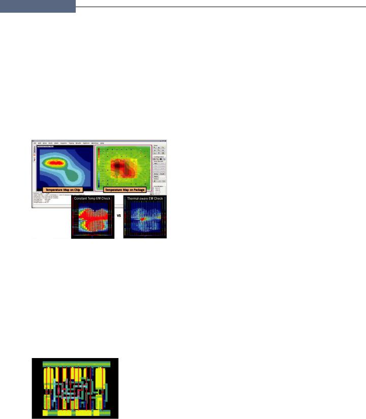
Thermal analysis of chip and package using ANSYS RedHawk-CTA
Wire temperatures used to calculate thermal-aware electromigration
Electromigration
The proliferation of automotive semiconductors based on leading-edge process nodes that enable ADAS and autonomous driving makes electromigration — a
lifetime reliability problem — a critical system design issue. Electromigration (EM) occurs when electrons flow through an integrated circuit and collide with the metal atoms in the
conductors and gradually create an open or a short. Over time, this causes the chip to fail. Chips become more susceptible to EM as their conductor cross section shrinks at each successive process node. EM also exponentially increases as a function of temperature. Advanced 2.5D and 3D integrated circuits are bringing dies closer together, creating the potential for more thermal hot spots.
Typically, the temperature of the individual conductors on a chip is not known, so design engineers assume a uniform worstcase temperature across the chip. This approach was satisfactory at older process nodes, but the faster switching speeds, narrower conductors and higher number of layers within today’s advanced
process nodes greatly increase the number of EM violations when this approach is used. Design teams spend increasing amounts of time evaluating and fixing these violations, many of which are false and would never have been triggered if the simulation had been based on an accurate nonuniform temperature profile.
The ANSYS RedHawk platform addresses these challenges by accurately determining the increase in temperature around the devices and metals to accurately predict EM violations. This increase in temperature is modeled using the Joule self-heat and thermal coupling principles between metal conductors inside a chip. The device temperature is a function of the amount of current consumed by each transistor as well as the proximity to neighboring transistors. Process parameters from the foundry combined with thermal characteristics
of the metals and dielectrics used on the die are used to accurately predict the localized temperature changes.
The temperature profile is used to perform thermal-aware EM checks based on the actual temperatures experienced by each wire on the chip. This approach greatly reduces the number of EM violations while providing much more diagnostic information than was available in the past to aid in addressing them. Engineers can zero in on the EM violations that really matter and can fix these violations faster. The result is a significant reduction in time to market and a lower risk of EM failure.
Thermal Performance
Thermal effects are another major concern in ensuring the reliability of critical automotive semiconductors. At the die and package level, engineers need to ensure that the temperatures across the chip do not exceed maximum operating temperatures at any point. Furthermore, they must evaluate thermal cycles during operation that generate deformation on the die and package because of differences in the coefficients of thermal expansion (CTEs) between the wafer and the metal layer. Thermal cycles at the board level can also generate stress due to differences
22 I ANSYS ADVANTAGE |
ISSUE 1 | 2018 |