


TABLE 6.27 List of Resolver and Synchro Suppliers
Company |
Location |
Phone number |
Types of resolvers |
|
|
|
|
API Harowe |
West Chester, PA |
(800) 566-5274 |
Brushless frameless, housed, & |
|
|
|
heavy-duty units |
Admotec, Inc. |
Norwich, VT |
(802) 649-5800 |
Rotasyn solid rotor resolvers |
Neotech, Inc. |
Hatfield, PA |
(215) 822-5520 |
Housed brush & brushless units |
Vernitron Corp. |
San Diego, CA |
(800) 777-3393 |
Brushless, segment, brushed, & |
|
|
|
housed units |
Servo Systems |
Montville, NJ |
(973) 335-1007 |
Brushed & brushless units |
American Electronics |
Fullerton, CA |
(714) 871-3020 |
Housed units |
Computer Conversions |
East Northport, NY |
(516) 261-3300 |
Explosion proof & specialty units |
Poltron Corp. |
Gaithersburg, MD |
(301) 208-6597 |
Resolvers |
Tamagawa Trading Co. |
Tokyo, Japan |
011-81-37-383-175 |
Brushless frameless & housed units |
MPC Products |
Skokie, IL |
(800) 323-4302 |
Housed resolvers |
Transicoil, Inc. |
Trooper, PA |
(800) 323-7115 |
Housed brushless & brushed |
|
|
|
resolvers |
Litton Poly-Scientific |
Blacksburg, VA |
(800) 336-2112 |
Brushed and brushless resolvers |
Kearfott Guidance & |
Wayne, NJ |
(973) 785-6000 |
Brushed & brushless resolvers |
Navigation Corp. |
|
|
|
Novatronics, Inc. |
Stratford, Ontario, Canada |
(519) 271-3880 |
Resolvers |
Muirhead Vactric |
Lake Zurich, IL |
(847) 726-0270 |
Resolvers |
|
|
|
|
Therefore, the approximate settling time for a large step would be 94 ms. This is an approximation. Synchros and resolvers are used in a wide variety of dynamic conditions. Understanding how the converter reacts to these input changes will allow one to optimize the bandwidth and maximum tracking rate for each application. Table 6.27 provides a list of resolver and synchro suppliers.
Further Information
Synchro/Resolver Conversion Handbook, 4th ed., Bohemia NY: ILC Data Device Corp., 1994.
Analog Devices, Inc., Analog-Digital Conversion Handbook, 3rd ed., Englewood Cliffs, NJ: Prentice-Hall, 1986.
Synchro & Resolver Conversion, East Molesey, UK: Memory Devices Ltd., 1980.
6.11 Optical Fiber Displacement Sensors
Richard O. Claus, Vikram Bhatia, and Anbo Wang
The objective of this section is to present a rigorous theoretical and experimental analysis of short gage length optical fiber sensors for measurement of cyclical strain on or in materials. Four different types of sensors are evaluated systematically on the basis of various performance criteria such as strain resolution, dynamic range, cross-sensitivity to other ambient perturbations, simplicity of fabrication, and complexity of demodulation process. The sensing methods that would be investigated include well-established technologies, (e.g., fiber Bragg gratings), and rapidly evolving measurement techniques such as longperiod gratings. Other than the grating-based sensors, two popular versions of Fabry–Perot interferometric sensors (intrinsic and extrinsic) will be evaluated for their suitability. A theoretical study of the cross-sensitivities of these sensors to an arbitrary combination of strain vectors and temperature, similar to that proposed by Sirkis in his SPIE paper in 1991 [1], will be developed.
The outline of this section is as follows. The principle of operation and fabrication process of each of the four sensors are discussed separately. Sensitivity to strain and other simultaneous perturbations such as temperature are analyzed. The overall cost and performance of a sensing technique depend heavily on the signal demodulation process. The detection schemes for all four sensors are discussed and compared
© 1999 by CRC Press LLC

on the basis of their complexity. Finally, a theoretical analysis of the cross-sensitivities of the four sensing schemes is presented and their performances are compared.
Strain measurements using optical fiber sensors in both embedded and surface-mounted configurations have been reported by researchers in the past [2]. Fiber optic sensors are small in size, immune to electromagnetic interference, and can be easily integrated with existing optical fiber communication links. Such sensors can typically be easily multiplexed, resulting in distributed networks that can be used for health monitoring of integrated, high-performance materials and structures. Optical fiber sensors for strain measurements should possess certain important characteristics. These sensors should either be insensitive to ambient fluctuations in temperature and pressure, or should have demodulation techniques that compensate for changes in the output signal due to the undesired perturbations. In the embedded configuration, the sensors for axial strain measurements should have minimum cross-sensitivity to other strain states. The sensor signal should itself be simple and easy to demodulate. Nonlinearities in the output demand expensive decoding procedures or require precalibrating the sensor. The sensor should ideally provide an absolute and real-time strain measurement in a form that can be easily processed. For environments where large strain magnitudes are expected, the sensor should have a large dynamic range while at the same time maintaining the desired sensitivity. A discussion of each of the four sensing schemes individually, along with their relative merits and demerits, follows.
Extrinsic Fabry–Perot Interferometric Sensor
The extrinsic Fabry–Perot interferometric (EFPI) sensor, proposed by Murphy et al., is one of the most popular fiber optic sensors used for applications in health monitoring of smart materials and structures [3]. As the name suggests, the EFPI is an interferometric sensor in which the detected intensity is modulated by the parameter under measurement. The simplest configuration of an EFPI is shown in Figure 6.99.
The EFPI system consists of a single-mode laser diode that illuminates a Fabry–Perot cavity through a fused biconical tapered coupler. The cavity is formed between an input single-mode fiber and a reflecting single-mode or multimode fiber. Since the cavity is external to the lead-in/lead-out fiber, the EFPI sensor is independent of transverse strain and small ambient temperature fluctuations. The input fiber and the reflecting fiber are aligned using a hollow-core silica fiber. For uncoated fiber ends, a 4% Fresnel reflection results at both ends. The first reflection, R1, called the reference reflection, is independent of the applied perturbation. The second reflection, R2, termed the sensing reflection, is dependent on the length of the cavity, d, which in turn is modulated by the applied perturbation. These two reflections interfere (provided 2d < Lc, the laser diode’s coherence length), and the intensity I at the detector varies as a function of the cavity length:
æ |
4p |
ö |
|
|
I = I0 cosç |
|
d÷ |
(6.117) |
|
l |
||||
è |
ø |
|
where, I0 is the maximum value of the output intensity and λ is the laser diode center wavelength. The typical EFPI transfer function curve is shown in Figure 6.100. Small perturbations that result in
operation around the quiescent-point or Q-point of the sensor lead to a linear variation in output intensity. A fringe in the output signal is defined as the change in intensity from a maximum to a maximum or from a minimum to a minimum. Each fringe corresponds to a change in the cavity length
by one half of the operating wavelength, λ. The change in the cavity length, |
d, is then employed to |
|||
calculate the strain ε using the expression: |
|
|||
e = |
Dd |
|
(6.118) |
|
L |
||||
|
|
|||
© 1999 by CRC Press LLC
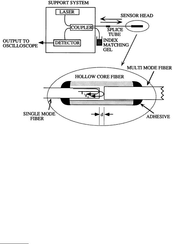
FIGURE 6.99 A simple configuration of an extrinsic Fabry–Perot interferometric (EFPI) sensing system.
where, L is defined as the gage length of the sensor and is typically the distance between two points where the input and reflecting fibers are bonded to the hollow-core fiber. Matching of the two reflection signal amplitudes allows good fringe visibility in the output signal.
The EFPI sensor has been extensively used for measuring fatigue loading on F-15 aircraft wings, detection of crack formation and propagation in civil structures, and cure and lifetime monitoring in concrete and composite specimens [2, 4]. The temperature insensitivity of this sensor makes it attractive for a large number of applications. The EFPI sensor is capable of measuring sub-Angstrom displacements with strain resolution better than 1 microstrain and a dynamic range greater than 10,000 µε. Although the change in output intensity of the EFPI is nonlinear corresponding to the magnitude of the parameter being measured, for small perturbations its operation can be limited to that around the Q-point of the transfer function curve. Moreover, the large bandwidth available with this sensor simplifies the measurement of highly cyclical strain. The EFPI sensor is capable of providing single-ended operation and is hence suitable for applications where access to the test area is limited. The sensor requires simple and inexpensive fabrication equipment and an assembly time of less than 10 min. Additionally, since the cavity is external to the fibers, transverse strain components that tend to influence intrinsic sensors through the Poisson’s effect have negligible effect on the EFPI sensor output. The sensitivity to only axial strain and insensitivity to input polarization state have made the EFPI sensor the most preferred fiber optic sensor for embedded applications [1]. Thus, overall, the EFPI sensing system is very well suited to measurement of small magnitudes of cyclical strain.
© 1999 by CRC Press LLC

FIGURE 6.100 A typical EFPI transfer function curve.
FIGURE 6.101 An intrinsic Fabry-Perot interferometric sensor (IFPI).
Although a version of the EFPI sensor that provides absolute output has been demonstrated, it lacks the bandwidth typically desired during the measurement of cyclical strain [5]. We have also recently proposed a small cavity length/high finesse EFPI sensor for measurement of small perturbations [6]. This configuration has a simple output that can be demodulated using an optical filter/photodetector combination.
Intrinsic Fabry–Perot Interferometric Sensor
The intrinsic Fabry–Perot interferometric (IFPI) sensor is similar in operation to its extrinsic counterpart but significant differences exist in the configurations of the two sensors [7]. The basic IFPI sensor is shown in Figure 6.101. An optically isolated laser diode is used as the optical source to one of the input arms of a bidirectional 2 × 2 coupler. The Fabry–Perot cavity is formed by fusing a small length of a single-mode fiber to one of the output legs of the coupler. As shown in Figure 6.101, the reference (R) and sensing (S) reflections interfere at the detector face to provide a sinusoidal intensity variation. The cavity can also be obtained by introducing two Fresnel reflectors — discontinuities in refractive index — along the length of a single fiber. Photosensitivity in germanosilicate fibers has been used in the past to fabricate broadband reflectors that enclose an IFPI cavity [8]. Since the cavity is formed within an optical
© 1999 by CRC Press LLC