

Laboratory work 3 Error correction principle of convolutional code with the threshold decoding algorithm
Objective: To study the coding and decoding principle of convolutional code with the threshold decoding algorithm
Laboratory emulator:
After running the program “HP VEE” and opening the file “DeKoder 0 2 5 6” you can see interface like fig. 3.3.
For simplifying, verification of corrective properties of single and double errors is executed when receiving zero-sequence. This is possible because CvC is linearity. Therefore, appearing unit bits in the zero-sequence 00 00 00 ... 00 corresponds to the errors in the input of decoder. In this case the correction of errors can be seen in the output sequence, if it only contains null bits.
This decoder correct single and double errors because dmin = 5. To check this you need in the windows "Информационные символы" and "Проверочные символы" enter the number of distorted binary symbols.
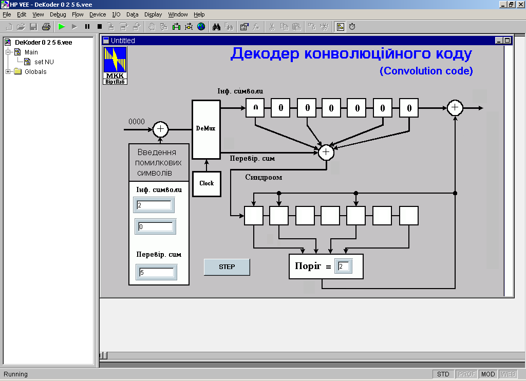
Figure 3.3 - The interface of laboratory work
For example, the numbers 2, 0 and 5 (zero means no error symbols) correspond to the received sequence 00 10 00 00 01 00, where errors in the second information bit and in the fifth check bit.
Performing multiple clicking on the button "Step", you can see the leading of bits in the information register Rg2 0100000, 0010000, 0001000, etc., the forming of the syndrome sequence in the register Rg3 and correction of error information bit with the help of output signal of threshold device.
As
you can see in fig. 3.3, syndrome register S0
will be equal to “0” in the case, when check bits of
the received sequence
![]() and the sequence of local check symbols
and the sequence of local check symbols
![]() are equal. Wise versa, if
are equal. Wise versa, if
![]() ,
S0
= 1, and it shows that there is an error in the received sequence.
So, the content of the cell S0
on the i-th
clock cycle:
,
S0
= 1, and it shows that there is an error in the received sequence.
So, the content of the cell S0
on the i-th
clock cycle:
S0i = D0i + D2i + D5i + D6i +
Cells of the Rg3: S3, S4, S6 are filled with usual shift:
S3i = S2i-1 S4i = S3i-1 S6i = S5i-1,
and another cells, according to influence from the threshold device, is calculated as:
S1i = S0i-1 TD i-1 S2i = S1i-1 TD i-1 S5i = S4i-1 TD i-1.
At the output of the decoder on each step, content of the cell D6 is added modulo 2 to the output of TD:
ai = D6i TDi.
In fig. 3.4 there is a listing of information and syndrome registers states at the correction of the double error 00 10 00 10 00 00 00 00.
|
D0 |
D1 |
D2 |
D3 |
D4 |
D5 |
D6 |
|
TD |
ai |
S0 |
S1 |
S2 |
S3 |
S4 |
S5 |
S6 |
0 |
0 |
0 |
0 |
0 |
0 |
0 |
0 |
|
0 |
0 |
0 |
0 |
0 |
0 |
0 |
0 |
0 |
1 |
1 |
0 |
0 |
0 |
0 |
0 |
0 |
|
0 |
0 |
1 |
0 |
0 |
0 |
0 |
0 |
0 |
2 |
0 |
1 |
0 |
0 |
0 |
0 |
0 |
|
0 |
0 |
0 |
1 |
0 |
0 |
0 |
0 |
0 |
3 |
1 |
0 |
1 |
0 |
0 |
0 |
0 |
|
0 |
0 |
0 |
0 |
1 |
0 |
0 |
0 |
0 |
4 |
0 |
1 |
0 |
1 |
0 |
0 |
0 |
|
0 |
0 |
0 |
0 |
0 |
1 |
0 |
0 |
0 |
5 |
0 |
0 |
1 |
0 |
1 |
0 |
0 |
|
0 |
0 |
1 |
0 |
0 |
0 |
1 |
0 |
0 |
6 |
0 |
0 |
0 |
1 |
0 |
1 |
0 |
|
0 |
0 |
1 |
1 |
0 |
0 |
0 |
1 |
0 |
7 |
0 |
0 |
0 |
0 |
1 |
0 |
1 |
|
1 |
0 |
1 |
1 |
1 |
0 |
0 |
0 |
1 |
8 |
0 |
0 |
0 |
0 |
0 |
1 |
0 |
|
0 |
0 |
1 |
0 |
0 |
1 |
0 |
1 |
0 |
9 |
0 |
0 |
0 |
0 |
0 |
0 |
1 |
|
1 |
0 |
1 |
1 |
0 |
0 |
1 |
0 |
1 |
10 |
0 |
0 |
0 |
0 |
0 |
0 |
0 |
|
0 |
0 |
0 |
0 |
0 |
0 |
0 |
0 |
0 |
|
↓ |
|
↓ |
|
|
↓ |
↓ |
|
Output of TD |
|
↓ |
↓ |
|
|
↓ |
|
↓ |
|
Syndrome adder modulo 2 |
|
← |
Input of threshold device |
|||||||||||||
Figure 3.4 – Illustration of the error correction by the CvC decoder (14, 7). Errors are in the second and in the fourth information bits.
On the 7-th clock cycle the decoder corrects the first error information bit, as the content of the syndrome register is 1110001. The input of the TD is S0+S1+S4+S6 = 1 + 1 + 0 + 1 = 3 > 2, that’s why the output of TD is “1”. Note that the content of the cells S18 = S07 1, S28 = S17 1, S58 = S47 1. As a result on the eighth step the syndrome register contents is set to 1001010. At the ninth clock cycle it will be 1100101 and decoder corrects the following error.
Laboratory task:
To run the program “HP VEE” and open the file “DeKoder 0 2 5 6”.
To check the correctness of the home task (form after fig. 3.5).
To check the corrective ability of the CvC (14, 7) for numbers incorrectly received code symbols given in the table 3.5.
Table 3.5 – Error correction of CvC (14, 7)
Multiplicity of the errors |
2 |
2 |
3 |
2 |
3 |
2 |
1 |
1 |
Numbers of information bits |
2 and 3 |
2 and 0 |
2 and 5 |
0 and 5 |
4 and 5 |
0 and 5 |
0 and 5 |
0 and 0 |
Number of check bit |
0 |
3 |
3 |
2 |
1 |
4 |
0 |
3 |
Corrective ability (+/–) |
|
|
|
|
|
|
|
|
Home task
To learn items 1.3.1 – 1.3.2 of this teaching manual.
To write down the answers to the general questions.
To draw a functional diagram of the coder and decoder with threshold decoding algorithm CvC (14, 7).
To fill a form shown in fig. 3.5 according to the variant in the table 3.4.
|
D0 |
D1 |
D2 |
D3 |
D4 |
D5 |
D6 |
|
TD |
ai |
S0 |
S1 |
S2 |
S3 |
S4 |
S5 |
S6 |
0 |
|
|
|
|
|
|
|
|
|
|
|
|
|
|
|
|
|
1 |
|
|
|
|
|
|
|
|
|
|
|
|
|
|
|
|
|
2 |
|
|
|
|
|
|
|
|
|
|
|
|
|
|
|
|
|
3 |
|
|
|
|
|
|
|
|
|
|
|
|
|
|
|
|
|
4 |
|
|
|
|
|
|
|
|
|
|
|
|
|
|
|
|
|
5 |
|
|
|
|
|
|
|
|
|
|
|
|
|
|
|
|
|
6 |
|
|
|
|
|
|
|
|
|
|
|
|
|
|
|
|
|
7 |
|
|
|
|
|
|
|
|
|
|
|
|
|
|
|
|
|
8 |
|
|
|
|
|
|
|
|
|
|
|
|
|
|
|
|
|
9 |
|
|
|
|
|
|
|
|
|
|
|
|
|
|
|
|
|
10 |
|
|
|
|
|
|
|
|
|
|
|
|
|
|
|
|
|
11 |
|
|
|
|
|
|
|
|
|
|
|
|
|
|
|
|
|
12 |
|
|
|
|
|
|
|
|
|
|
|
|
|
|
|
|
|
13 |
|
|
|
|
|
|
|
|
|
|
|
|
|
|
|
|
|
Figure 3.5 – Form for home task
Table 3.4 – Personal variant for home task
For each person |
Number of brigade |
|||||||
1 |
2 |
3 |
4 |
5 |
6 |
7 |
8 |
|
1 |
1, 0 |
3, 5 |
5, 0 |
2, 3 |
1, 5 |
1, 6 |
4, 5 |
2, 6 |
2 |
1, 7 |
2, 4 |
1, 4 |
4, 6 |
3, 4 |
3, 0 |
2, 7 |
4, 0 |
3 |
1, 3 |
1, 2 |
3, 6 |
2, 0 |
6, 0 |
2, 5 |
5, 6 |
3, 7 |
General questions:
Which classes do convolutional codes with threshold decoding algorithm belong to?
Describe the main parameters of convolutional codes.
Determine the main parameters of CvC (14, 7).
What is perfect difference set?
Which property of the perfect DS is used in threshold decoding?
Describe the work of the CvC coder.
Describe the work of the convolutional decoder with threshold decoding method.
When is unit bit formed on the output of the TD?
Why is the feedback of the TD used?
Protocol content:
Subject
Objective.
Executed home task.
Table 3.5 according to laboratory task.
Conclusion about how many errors this decoder corrects and why don’t all triple errors correct.