

Introduction to 3D Game Programming with DirectX.9.0 - F. D. Luna
.pdf54Chapter 1
Delete—This template function is designed as a convenience function to delete an object on the free store and set the pointer to null.
WndProc—The window procedure declaration for the main application window
1.5.2 Sample Framework
By sample framework we are referring to the general way that we structure the sample applications of this book. For each sample we consis-
tently implement three functions, not counting the message procedure |
||
|
|
F |
and WinMain. These three functions are used to implement the code |
||
specific to the particular sample. They are:Y |
||
|
|
M |
|
bool Setup()—This functionLis where we set up anything that |
|
|
A |
|
|
needs to be set up for this sample, such as allocating resources, |
|
|
checking device capabilities, and setting application states. |
|
|
E |
|
|
void Cleanup()—This function is where we free anything that |
|
|
T |
|
|
we allocated in the Setup function, such as deallocating memory. |
|
|
bool Display(float timeDelta)—This function is where |
|
|
we implement all of our drawing code and code that occurs on a |
|
frame-by-frame basis, such as updating object positions. The parameter timeDelta is the time elapsed between each frame and is used to sync animations with the frames per second.
1.5.3 Sample: D3D Init
As stated, the sample application creates and initializes a Direct3D application, and then clears the screen to black. Note that we make use of our utility functions to simplify initialization. The complete project can be found on this chapter’s page on the book’s web site.
Note: This sample closely follows the ideas discussed in Tutorial 1 in the DirectX SDK documentation. You may wish to read Tutorial 1 after this chapter to gain a different perspective.
We start out by including d3dUtility.h and instantiating a global variable for the device:
#include "d3dUtility.h"
IDirect3DDevice9* Device = 0;
Next we implement our framework functions:
bool Setup()
{
Team-Fly®

Direct3D Initialization 55
return true;
}
void Cleanup()
{
}
We don’t have any resources or things to set up in this sample, so the Setup and Cleanup methods are empty.
bool Display(float timeDelta)
{
if( Device )
{
Device->Clear(0, 0, D3DCLEAR_TARGET | D3DCLEAR_ZBUFFER, 0x00000000, 1.0f, 0);
Device->Present(0, 0, 0, 0);// present backbuffer
}
return true;
}
The Display method calls the IDirect3DDevice9::Clear method, which clears the back buffer and depth/stencil buffer to the color black and 1.0, respectively. Notice that we only perform the drawing code if the application is not paused. The declaration of
IDirect3DDevice9::Clear is:
HRESULT IDirect3DDevice9::Clear( DWORD Count,
const D3DRECT* pRects, DWORD Flags,
D3DCOLOR Color, float Z,
DWORD Stencil
);
Count—Number of rectangles in the pRects array
pRects—An array of screen rectangles to clear. This allows us to only clear parts of a surface.
Flags—Specifies which surfaces to clear. We can clear one or more of the following surfaces:
D3DCLEAR_TARGET—The render target surface, usually the back buffer
D3DCLEAR_ZBUFFER—The depth buffer
D3DCLEAR_STENCIL—The stencil buffer
Color—The color we wish to clear the render target to
Z—The value we wish to set the depth buffer (z-buffer) to
Stencil—The value we wish to set the stencil buffer to
P a r t I I

56 Chapter 1
After the surfaces have been cleared, we present the back buffer by calling the IDirect3DDevice9::Present method.
The window procedure method handles a couple of events; namely it allows us to exit the application by pressing the Escape key.
LRESULT CALLBACK d3d::WndProc(HWND hwnd, UINT msg, WPARAM wParam, LPARAM lParam)
{
switch( msg )
{
case WM_DESTROY: ::PostQuitMessage(0); break;
case WM_KEYDOWN:
if( wParam == VK_ESCAPE ) ::DestroyWindow(hwnd);
break;
}
return ::DefWindowProc(hwnd, msg, wParam, lParam);
}
Finally, WinMain performs the following steps:
1.Initializes the main display window and Direct3D
2.Calls the Setup routine to set up the application
3.Enters the message loop using Display as the display function
4.Cleans up the application and finally releases the IDirect3DDevice9 object
int WINAPI WinMain(HINSTANCE hinstance, HINSTANCE prevInstance, PSTR cmdLine,
int showCmd)
{
if(!d3d::InitD3D(hinstance,
800, 600, true, D3DDEVTYPE_HAL, &Device))
{
::MessageBox(0, "InitD3D() - FAILED", 0, 0); return 0;
}
if(!Setup())
{
::MessageBox(0, "Setup() - FAILED", 0, 0); return 0;
}
d3d::EnterMsgLoop( Display );
Cleanup();
Device->Release();

Direct3D Initialization 57
return 0;
}
As you can see, our sample template structure is quite clean with our utility function handling the window and Direct3D initialization processes. For almost every sample program in this book, our task is to fill out the implementations for the Setup, Cleanup, and Display functions.
Note: Remember to link in d3d9.lib, d3dx9.lib, and winmm.lib if you are building these samples on your own.
1.6 Summary
|
|
II |
|
Direct3D can be thought of as a mediator between the programmer |
|||
rt |
|||
and the graphics hardware. The programmer calls a Direct3D func- |
|||
Pa |
|||
tion, which in turn, indirectly, has the physical hardware perform |
|||
the operation by interfacing with the device’s HAL (Hardware |
|
||
|
|||
Abstraction Layer). |
|
||
The REF device allows developers to test features that Direct3D |
|
||
exposes but are not implemented by available hardware. |
|
||
Component Object Model (COM) is the technology that allows |
|
||
DirectX to be language independent and have backward compatibil- |
|
||
ity. Direct3D programmers don’t need to know the details of COM |
|
||
and how it works; they only need to know how to acquire COM |
|
||
interfaces and release them. |
|
||
Surfaces are special Direct3D interfaces used to store 2D images. |
|
||
A member of the D3DFORMAT enumerated type specifies the pixel |
|
||
format of a surface. Surfaces and other Direct3D resources can be |
|
||
stored in several different memory pools as is specified by a mem- |
|
||
ber of the D3DPOOL enumerated type. In addition, surfaces can be |
|
||
multisampled, which creates a smoother image. |
|
||
The IDirect3D9 interface is used to find out information about |
|
||
the system’s graphics devices. For example, through this interface |
|
||
we can obtain the capabilities of a device. It is also used to create |
|
||
the IDirect3DDevice9 interface. |
|
||
The IDirect3DDevice9 interface can be thought of as our soft- |
|
||
ware interface for controlling the graphics device. For instance, |
|
||
calling the IDirect3DDevice9::Clear method will indirectly |
|
||
have the graphics device clear the specified surfaces. |
|
||

58Chapter 1
The sample framework is used to provide a consistent interface that all sample applications in this book follow. The utility code provided in the d3dUtility.h/cpp files wrap initialization code that every application must implement. By wrapping this code up, we hide it, which allows the samples to be more focused on demonstrating the current topic.

Chapter 2
The Rendering
Pipeline
The primary theme of this chapter is the rendering pipeline. The rendering pipeline is responsible for creating a 2D image given a geometric description of the 3D world and a virtual camera that specifies the perspective from which the world is being viewed.
Figure 2.1: The left image shows some objects set up in the 3D world with a camera positioned and aimed. The image on the right shows the 2D image created based on what the camera “sees.”
Objectives
To find out how we represent 3D objects in Direct3D
To learn how we model the virtual camera
To understand the rendering pipeline—the process of taking a geometric description of a 3D scene and generating a 2D image from it.
59

60 Chapter 2
2.1 Model Representation
A scene is a collection of objects or models. An object is represented as a triangle mesh approximation, as Figure 2.2 illustrates. The triangles of the mesh are the building blocks of the object that we are modeling. We use the following terms all interchangeably to refer to the triangles of a mesh: polygons, primitives and mesh geometry. (Although triangles are primitives, Direct3D also supports line and point primitives. However, since lines and points aren’t useful for modeling 3D solid objects, we omit a discussion of these primitive types. We do discuss some applications of points in Chapter 14.)
Figure 2.2: A terrain approximated by triangles
The point where two edges on a polygon meet is a vertex. To describe a triangle we specify the three point locations that correspond to the three vertices of the triangle (see Figure 2.3). Then to describe an object, we specify the triangles that make it up.
Figure 2.3: A triangle defined by its three vertices

The Rendering Pipeline 61
2.1.1 Vertex Formats
The previous definition of a vertex is correct mathematically, but it is an incomplete definition when used in the context of Direct3D. This is because a vertex in Direct3D can consist of additional properties besides a spatial location. For instance, a vertex can have a color property as well as a normal property (colors and normals are discussed in Chapters 4 and 5, respectively). Direct3D gives us the flexibility to construct our own vertex formats; in other words it allows us to define the components of a vertex.
To create a custom vertex format, we first create a structure that holds the vertex data that we choose. For instance, below we illustrate two different kinds of vertex formats; one consists of position and color, and the second consists of position, normal, and texture coordinates (see Chapter 6, “Texturing”).
struct ColorVertex |
|
{ |
|
float _x, _y, _z; |
// position |
DWORD _color; |
|
}; |
|
struct NormalTexVertex |
|
{ |
|
float _x, _y, _z; |
// position |
float _nx, _ny, _nz; |
// normal vector |
float _u, _v; |
// texture coordinates |
}; |
|
Once we have the vertex structure completed, we need to describe the way that the vertices are formatted by using a combination of flexible vertex format (FVF) flags. Using the previous two vertex structures, we have the following vertex formats:
#define FVF_COLOR (D3DFVF_XYZ | D3DFVF_DIFFUSE)
Put into words, the above says that the vertex structure that corresponds to this vertex format contains a position property and a diffuse color property.
#define FVF_NORMAL_TEX (D3DFVF_XYZ | D3DFVF_NORMAL | D3DFVF_TEX1)
The above says that the vertex structure that corresponds to this vertex format contains position, normal, and texture coordinate properties. One restriction that must be taken into consideration is that the
order in which you specify the flexible vertex flags must be the same order in which you specify the data in the vertex structure.
Look up D3DFVF in the documentation for a complete list of the available vertex format flags.
P a r t I I

62 Chapter 2
2.1.2 Triangles
Triangles are the basic building blocks of 3D objects. To construct an object, we create a triangle list that describes the shape and contours of the object. A triangle list contains the data for each individual triangle that we wish to draw. For example, to construct a rectangle, we break it into two triangles, as seen in Figure 2.4, and specify the vertices of each triangle.
Figure 2.4: A rectangle built from two triangles
Vertex rect[6] = {v0, v1, v2, // triangle0
v0, v2, v3}; // triangle1
Note: The order in which you specify the vertices of a triangle is important and called the winding order. See section 2.3.4 for information.
2.1.3 Indices
Often the triangles that form a 3D object share many of the same vertices, as the rectangle in Figure 2.4 illustrates. Although only two vertices are duplicated in the rectangle example, the number of duplicate vertices can increase as the detail and complexity of the model increases. For instance, the cube in Figure 2.5 has eight unique vertices, but many of them would be duplicated to form the triangle list for the cube.
Figure 2.5: A cube defined by triangles
The Rendering Pipeline 63
To solve this problem we introduce the concept of indices. It works like this: We create a vertex list and an index list. The vertex list consists of all the unique vertices, and the index list contains values that index into the vertex list to define how they are to be put together to form triangles. Returning to the rectangle example, the vertex list would be constructed as follows:
Vertex vertexList[4] = {v0, v1, v2, v3};
Then the index list needs to define how the vertices in the vertex list are to be put together to form the two triangles.
WORD indexList[6] = {0, 1, 2, // triangle0
0, 2, 3}; // triangle1
Put into words, the indexList definition says to build triangle0 from elements zero (vertexList[0]), one (vertexList[1]), and two (vertexList[2]) of the vertex list and build triangle1 from elements zero (vertexList[0]), two (vertexList[2]), and three (vertexList[3]) of the vertex list.
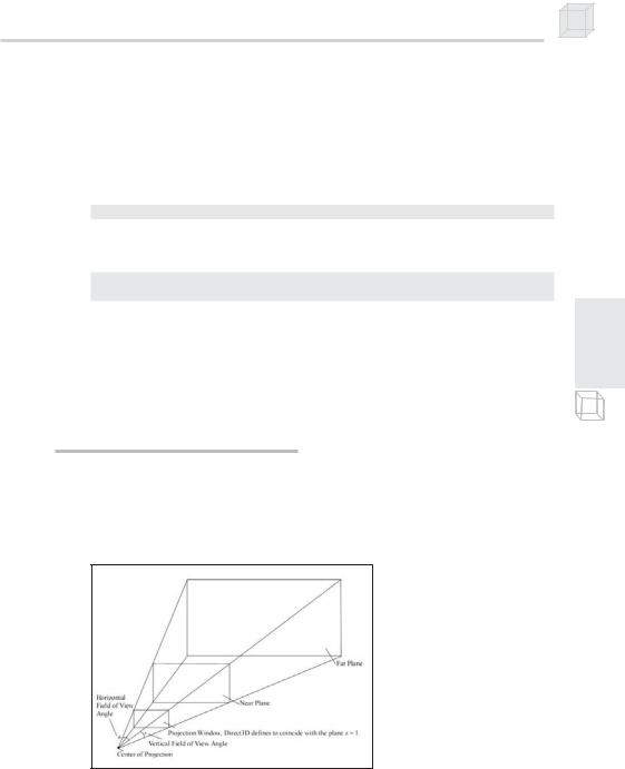
2.2 The Virtual Camera
The camera specifies what part of the world the viewer can see and thus what part of the world for which we need to generate a 2D image. The camera is positioned and oriented in the world and defines the volume of space that is visible. Figure 2.6 shows a diagram of our camera model.
P a r t I I
Figure 2.6: A frustum that defines the volume of space that the camera “sees”
The volume of space is a frustum and defined by the field of view angles and the near and far planes. The reasons for using a frustum should be made clear when you consider that your monitor screen is rectangular. Objects that are not inside this volume cannot be seen and should be