

02 BOPs / Woods D.R 2008 rules-of-thumb-in-Engineering-practice (epdf.tips)
.pdf5.25 Spiral Classifiers 181
5.24
Rake Classifiers
Superceded by hydrocyclones. (Sections 5.22 and 5.9)
5.25
Spiral Classifiers
x Area of Application
Bird number (mass of solids with a e0.1 density variation from the cut density) I 15; particle cut diameter i 50 mm but usually 1000 to 20 000 mm.
x Guidelines
Two types: cut diameter i 200 mm use high weir configuration; cut diameter I 200 mm use submerged spiral. Size based on the target exit overflow concentration and “limiting” particle diameter. Diameter of the limiting particle should have a settling velocity double that of the cut diameter (cut diameter is about 70 % of the limiting diameter).
Separation efficiency is 50 %; that is, use double the cross section area obtained from the settling velocity of the “limiting” particle diameter.
Capacity 2 to 250 kg/s.
Underflow solids capacity is a function of the spiral diameter and solids density; independent of the separation. Angle of inclination 16h.
High weir: 1 m2 pool area produces about 5 kg/s dry solids in the overflow with 400 mm limiting diameter or about 280 mm cut diameter and 30 % concentration. Submerged weir: 1 m2 pool area produces about 0.5 kg/s dry solids in the overflow with 150 mm limiting diameter or about 100 mm cut diameter and 16 % concentration.
For both configurations, increasing the area by a factor of 10 increases the amount of overflow solids by 10 with the same cut and limiting diameters and overflow concentrations.
Rotational speed increases with the cut diameter.
x Good Practice
Feed concentration between 10 to 50 % w/w solids. Dilution water is the important operating variable.

1825 Heterogeneous Separations
5.26
Jig Concentrators
x Area of Application
Bird no. (mass of solids with a e0.1 density variation from the cut density) I 15; relative density ratio 2 to 2.5 and particle diameter 2 to 10 mm. Feed concentration 1.5 to 30 % w/w.
x Guidelines
Loading 1 to 8 kg/s m2 with loading increasing with increase in particle diameter. Power 1 kW/m2 and water usage 13 L/s m2.
x Good Practice
Keep feedrate constant. Add surge and storage tanks to aid control. Keep feed free from a high portion of fines.
5.27
Table Concentrators
x Area of Application
Bird number (mass of solids with a e0.1 density variation from the cut density) I 15; relative density ratio i 2 to 2.5; usual particle diameter 70 to 2000 mm; only one valuable mineral. Tilting frames: density ratio 2.5 and particle diameter i 50 mm ranging to density ratio of 1.25 with particle diameter i 5 mm. Holman slimes table for I 70 mm.
x Guidelines
7 to 12 m2 per unit; 6h incline; usual capacity 0.03 to 0.06 kg/s m2. The higher the Bird no., the lower the capacity, power 0.15 kW/m2; wash water 0.1 to 0.3 L/s m2.
x Good Practice
Constant mass feedrate and constant physical properties.
5.28
Sluice Concentrators
x Area of Application
Bird number (mass of solids with a e0.1 density variation from the cut density) I 15; relative density ratio i 1.8; usual particle diameter 400 to 3000 mm; only one valuable mineral.

5.30 Screens 183
x Guidelines
Humphreys and Reichert Spiral: capacity/unit: 0.25 to 1.5 kg/s to handle particle diameters 75 mm to 2 mm.
x Good Practice
Constant feedrate and constant diameter of heavy particles.
5.29
Dense Media Concentrators, DMS
x Area of Application
Systems with a narrow range of particle size but with a range in densities. Bird number (mass of solids with a e 0.1 density variation from the cut density) 15 i Bi i 25; relative density ratio i 1.25 to 1.5; usual particle diameter i 10 mm.
x Guidelines
Choose media with density between desired cuts. For media with density 1.2 to 2.2 use magnetite; for 2.9 to 3.4 use ferrosilicon. Use mixtures for intermediate densities: 2.5 to 15 kg/s m2 of pool area.
x Good Practice
Prescreen feed to eliminate fines and clay. Consider DMS before liberation grinding.
5.30 Screens
(see also Section 5.7 for liquid–solid separation) Screens can be used to:
–wash or dewater, see Section 5.7.
–scalp: remove 5 % of oversize and have i 50 % half size.
–screen: remove fines I 425 mm.
–size or separate: choice depends on particle size: coarse i 4.75 mm; intermediate size between 425 and 4750 mm and fines between 45 and 425 mm; see filters, Section 5.14, centrifugal filters, Section 5.13 and expellers, Section 5.17.
x Area of Application
Grizzly: particle diameter 15 to 30 cm and i 30 cm; Use: primarily to scalp, screen fines.
– rod grizzly: particle diameter 8 to 30 cm. Use: primarily to scalp.
Rod deck screen: particle diameter 0.75 to 8 cm. Use: scalp, dewater and separate. Sieve bend: particle diameter: 45 to 2000 mm; Use: dewater, separate intermediate and fines: 45 to 4750 mm.

184 5 Heterogeneous Separations
Revolving screen: Trommel particle diameter 3 mm to 50 cm; feed solids concentration 5 to 25 %. Use: separation.
Revolving screen: centrifugal: particle diameter: 400 to 1200 mm; Use: dewater, separate intermediate diameters and use high speed for fines.
Revolving screen: probability: particle diameter I 6 mm; Use: separate intermediate and fines 45 to 4750 mm.
High speed vibrating horizontal screen (600 to 3000 rpm with low amplitude
I 2.5 cm): 3 to 100 mm. Use for dense granular materials i 0.3 Mg/m3 Use: wash, dewater, scalp, screen fines, separate coarse.
High speed vibrating inclined screen (600 to 7000 rpm with low amplitude
I 2.5 cm): 200 to 100 000 mm. Use for dense granular i 0.3 Mg/m3. Use: wash, scalp and separation of wide range of particle diameters.
Low speed oscillating screen (25 to 500 rpm with 15 to 30 mm amplitude): 74 to 12 000 mm especially for lower density solids; although some suppliers recommend this for only i 12 000 mm. Use: separate.
Gyratory in plane of the screen (500 to 600 rpm; 5h inclination): fine separations particle diameter 50 to 4000 mm.
x Guidelines
Screen: efficiency 85 to 95 %; length/width of screen 2:1 to 1.5:1; rate of travel of solids along the screen face 0.3 to 0.5 m/s. The flux of solids passing through the screen is about: for coarse particle diameters, 2 to 5 kg/s m2; for intermediate particle diameters 0.4 to 4 kg/s m2; for fine particle diameters 0.08 to 0.4 kg/s m2 with fluxes decreasing as the density decreases.
Trommels: rotational speed should be slow enough that the particles free fall (about 45 % of the transition rpm). L/D = 2:1 to 5:1; residence time 30 to 60 s with flux rates of 0.03 to 0.1 kg/s m2.
x Good Practice
If damp or sticky, predry or use heater above the screen to reduce moisture to I 3 %. Avoid resonance frequencies. Usual angle of operation is 12 to 18h; for wet, inclined vibrating screen to 7 to 11h. Capacity decreases if the angle of inclination is too high. Blinding is mainly caused by material that is 1 to 1.5 times the hole size. Feed thickness should not exceed 4 q aperture size for 1.6 Mg/m3; and not exceed 2 to 3 q aperture size for 0.8 Mg/m3.
x Trouble Shooting
“Capacity decreases”: angle of inclination too high/blinding.
References
Turner, J. et al., 1999 (June), HP, 119. Woods, D. R., 1994, Process Design and Engi-
neering Practice, Prentice Hall, Englewood Cliffs, NJ.

6 Reactors
In this chapter the focus is on reactors. First we introduce the general factors that affect the selection of the reactor. In Section 6.2 are given general guidelines. Section 6.3 considers details for different types of reactions that affect the size of the reactor. The rest of the chapter discusses some specifics about the different types of reactor. Section 6.4 considers burners. Plug flow tubular reactors, PFTR, are considered in Sections 6.5 to 6.26. Stirred tanks reactors, STR, are considered in Section 6.27 to 6.33. Finally Sections 6.34 to 6.37 explore combining reactors with other unit operations such as distillation, extrusion, membranes and vacuum pumps.
6.1
Factors Affecting the Choice of Reactor
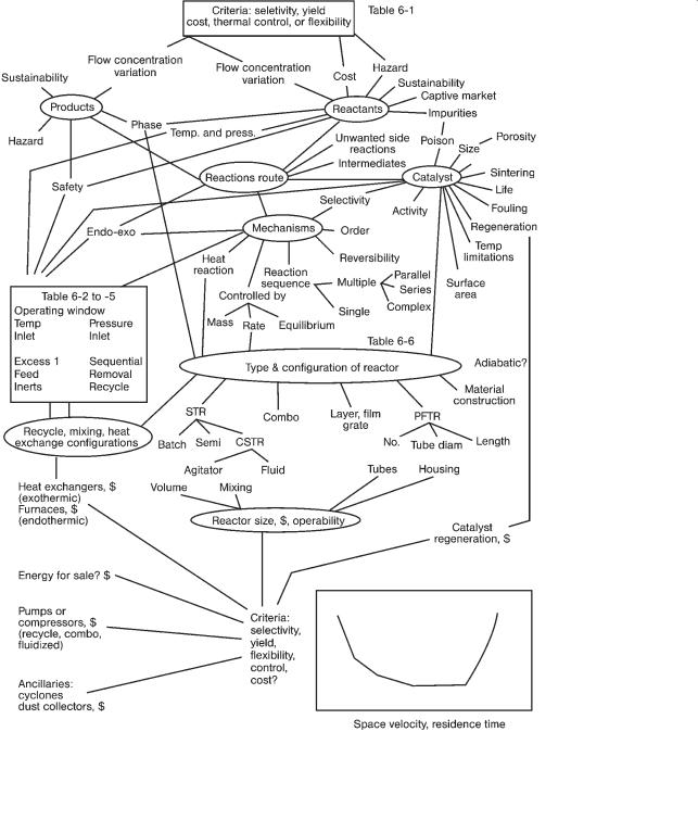
The general selection procedure or “sizing map” for reactors is given in Fig. 6.1. In this map we start at the upper left-hand side by considering the products: issues of sustainability, the impact on the environment and the hazards associated with the product. Naturally we need to know the production capacity or flow and concentration or purity of the product. The final selection of the reactor is an optimization based on the selected design criteria and is shown in the bottom right-hand corner of Fig. 6.1. Unlike the sizing of most process equipment, where the optimization function is cost, for reactors the optimization criteria may be selectivity, yield, flexibility, ability to control, cost or health and safety. The design criterion is usually selectivity or cost but Table 6.1 provides guidelines for selecting the criterion. The design variable is usually the contact time in the reactor.
To move through the sizing process we consider various reactants, top RHS of Fig. 6.1 and select possible reaction routes from the chemistry, understand competing and unwanted side reactions, select the phases and decide if a catalyst should be used. As illustrated on the RHS of Fig. 6.1, having a catalyst introduces questions of selectivity, activity, size, porosity, life, contaminants and poisons that interfere with the catalyst’s function and temperature limitations. Our choice of reaction route also sets the heat release from the reaction; highly exothermic or
Rules of Thumb in Engineering Practice. Donald R. Woods
Copyright c 2007 WILEY-VCH Verlag GmbH & Co. KGaA, Weinheim
ISBN: 978-3-527-31220-7
186 6 Reactors
Figure 6.1 Sizing map.

6.1 Factors Affecting the Choice of Reactor 187
Table 6.1 Criteria for selecting reactor.
Criterion to use: If the following issues apply:
|
Cost of raw |
Ease of |
Reactions |
Variability in |
|
materials |
recovery of |
|
demand, feed- |
|
|
unreactea |
|
stocks, product |
|
|
feed |
|
specifications |
|
|
|
|
|
Selectivity |
cheap |
easy |
multiple reactions producing byproducts |
|
Yield |
expensive |
difficult |
|
|
Flexibility |
|
|
|
great variation |
Cost |
|
|
single reaction |
|
Thermal control |
|
|
highly exothermic |
|
Health and |
|
|
Highly endothermic or exothermic |
|
safety; environ- |
|
|
reactions, see Table 6-3. Hazardous |
|
mental, hazards. |
|
|
reactions: azides, peroxides, perchlorates |
|
|
|
|
or nitro compounds. Reactions of the type*: |
|
|
|
|
decomposition, nitration, oxidation, |
|
|
|
|
polymerization, alkylation, amination, |
|
|
|
|
combustion, condensation, diazotization, |
|
|
|
|
halogenation or hydrogenation. |
|
* Only some of the reactions in each type pose a hazard.
endothermic? Highly exothermic reactions sensitize us to the concern for reactor safety and reliability.
Thus we are led, through an iterative process, to the selection of the conditions for operating the reactor (called the operating window and shown midway on the LHS of Fig. 6.1). Start first with the chemistry of the target and unwanted competing reactions. Use Le Chatelier’s principle, then equilibrium considerations and finally reaction rates – if needed – to suggest temperatures and pressures that will maximize the target reaction and minimize the unwanted reactions. Use Table 6.2 to select the use of recycle, inerts or excess reactants and temperature. The overall theme is to have the desired reaction to proceed quickly and safely. A major consideration is that many reactions are highly exoor endothermic.
A highly endothermic reaction may extinguish the reaction before it is complete. Highly exothermic reactions require a strategy for the safe control of the heat release. Three options to control the heat release are: (i) dilute the reactants or add inerts so that the heat release is slower and more manageable, (ii) use undiluted reactants and control the rate of reaction (or mass transfer) by using lower temperatures and (iii) use undiluted reactants and control the heat removal via reactor design and process control to manage the non-adiabatic operation. Usually we select options 2 or 3. Table 6.3 lists a range of dimensionless groups that can be used to identify the amount of heat released, the speed of the reaction and the

188 6 Reactors
Table 6.2 Selecting operating window with respect to temperature, inerts and recycle.
Heat of reaction |
Reversible |
Order of irre- |
Inlet temperature |
Control of temperature |
|
|
reaction? |
versible reactions |
|
|
|
|
|
|
|
adiabatic |
non-adiabatic |
|
|
|
|
|
|
endothermic |
yes |
|
T = (Max. catalyst |
add inerts |
Use method to |
|
|
|
temp. – 25 hC) |
|
add heat? |
|
no |
Order of the target |
|
add excess of |
|
|
|
(a1) i order of |
|
one reactant |
|
|
|
the undesired (a2) |
|
|
|
exothermic |
yes |
|
|
add inerts and |
Use configura- |
(typical of many |
|
|
|
recyle |
tion or methods |
reactions in the |
|
|
|
|
to remove heat. |
liquid phase) |
|
|
|
|
|
|
no |
Order of target |
T = (Max. catalyst |
|
|
|
|
reaction (a1) |
temp. – 25 hC) |
|
|
|
|
i order of the |
|
|
|
|
|
undesired (a2) |
|
|
|
|
|
|
|
|
|
cooling capacity of the system. Consider the product of DTad+ with the Arrhenius number to be a measure of the heat released. If the product is i 5 to 10 for irreversible reactions, then there is the potential for a thermal runaway reaction. Considering the relative importance of the speed of the reaction and the cooling capacity: if the ratio of the Damkohler number to the modified Stanton number is I 0.1, then a batch reactor is probably safe. But if the ratio is i 1, then a batch reactor is likely to be unsafe; a semibatch operation will allow the gradual addition of the reactants to better control the heat release. The combination of Tables 6.2 and 6.3 gives starting guidelines for the range of temperature. Table 6.4 adds another perspective for the selection of the temperature.
Table 6.5 gives guidelines for selecting the pressure for the operating window. The pressure and temperature affect the strength of the material. For example, Fig. 6.2 shows the code design for pressure vessels, coded 300, 400, 600, 1500 and 2500 for carbon steel. At temperatures above 350 hC, the strength of carbon steel decreases so that carbon molybdenum steels are preferred. Also shown in this figure are the behaviors of steel alloys: austenitic steels and chrome molybdenum.
Ideally, we prefer an operating window between 20 and 250 hC and 0.1 to 1 MPa so that we can use water as a coolant and steam for heating. This window is shown in Fig. 6.2. Also plotted (as data points) are the operating conditions for a variety of commercial reactions. Many fall in the ideal target window. If a catalyst is used this adds additional temperature constraints to the constraints posed by the strength of materials. Those reactions at the higher temperatures tend to be homogeneous reactions.

6.1 Factors Affecting the Choice of Reactor 189
Table 6.3 Parameters related to hazard and reactor safety.
|
Word definition |
Equation |
Significant value |
So what? |
|
|
|
|
|
Heat of reaction, |
Highly exothermic |
|
i 150 MJ/kmol |
safety concern |
DHreact |
or highly endother- |
|
|
|
|
mic |
|
|
|
DT+ad. Dimension- |
adiabatic tempera- |
= heat of reaction q |
safe if |
If i 50 hC, explore |
less Adiabatic tem- |
ture change ac- |
mol fraction major |
DTad I 50 hC |
options to design |
perature increase, |
companying com- |
reactant at inlet/ |
|
the reactor and |
where the adiabatic |
plete consumption |
average gaseous |
|
manage the heat |
temperature rise |
of the reactant |
molar heat capacity |
|
release. |
DTad = (Tad – To) |
without regard to |
= (–DHreact ) xAo/cpT |
|
|
is divided by the |
equilibrium con- |
|
|
|
inlet temperature |
siderations divided |
= (–DHreact ) cAo/rG |
|
|
|
by inlet tempera- |
cpT |
|
|
|
ture |
|
|
|
Arrhenius number, Arr no.
Arr no. (DT+ad.)
Thermal reaction number or Excessive heat generation (some authors assign this the symbol b and others gb)
Damkohler no. dimensionless reaction rate
modified Stanton no. or cooling capacity
activation energy |
E/ RT |
typical range is |
Used in reaction |
divided by the ideal |
where E = activation |
10–40, and 5–30 |
rates and in safety |
gas constant q ab- |
energy |
for gas–solid |
analysis as part |
solute temperature |
|
or liquid–solid |
of the Thermal |
|
|
reactions |
Reaction no. |
adiabatic tempera- |
(E/RT) (DTad/T) |
range 1–50; safe if |
If i 10, explore op- |
ture increase q |
|
I 5 to 10 |
tions to design the |
heat generation |
(Arr) (DT+ad.) |
|
reactor and manage |
potential |
|
|
the heat release. |
rate of reaction/ |
equation depends |
Combine Da with |
Da/St I 1 then ok |
rate of convection |
on the rate expres- |
Stanton no; Da/St. |
to use batch; |
|
sion |
|
if i 1 use semibatch |
heat transfer |
UAt/Vr cp |
|
|
ability/sensible |
|
|
|
heat sink |
where U = overall |
|
|
|
heat transfer coeffi- |
|
|
|
cient, |
|
|
|
A = area |
|
|
|
t = time |
|
|
|
V = volume |
|
|
|
r = density |
|
|
|
cp = heat capacity |
|
|

190 6 Reactors
Table 6.4 Selecting operating temperature.
Range
Must operate so that the correct phase is present.
Want to select temperature that minimizes the significant side reactions.
Want to operate from 20–250 hC to minimize utility cost by using water and steam.
For adiabatic |
For reversible exothermic or some |
For endothermic reactions or |
|
irreversible catalytic, optimize |
irreversible exothermic |
|
to select best temperature. Recall |
|
|
that high selectivity and high |
|
|
yield are usually very sensitive to |
|
|
temperature. |
|
then the minimum is set by:
For gases, must be i dew point. For liquids, i freezing temperature.
Prefer the minimum temperature for exothermic (LeChatelier, F) but the rate of reaction is reduced
then midway is set by:
For non-adiabatic gas catalytic operation, by the jacket temperature.
then the maximum is set by:
For liquids, I boiling temperature. and use
25 hC less than the following max. catalyst temperature, exothermic adiabatic reaction temperature, or
temperature limitations of the materials of construction.
Table 6.5 Select operating pressure.
Range: usually I 100 MPa
Must operate so that the correct phase is present.
Want to select a pressure that minimizes significant side reactions. Want to operate from 0.1–1 MPa to minimize utility cost.
Want to use the minimum possible pressure or the least vacuum
Use the minimum
If reversible and more moles are produced as product than moles of reactants (LeChatelier, F). If the target reaction is of lower order than the undesired reactions.
If large volume of gas needs to be compressed for recycle.
Maximum is suggested by
the maximum feed pressure of reactants. the cost of recycle.
the pressure limitations of the materials of construction.
the pressure drop across device or through the catalyst bed.
If reversible and more moles as reactants than as products (Le Chatelier, F).
If target reaction is of higher order than the undesired reactions.
If the main reaction is slow.