

02 BOPs / Woods D.R 2008 rules-of-thumb-in-Engineering-practice (epdf.tips)
.pdf4.2 Distillation 91
Fundamentals: use simplified McCabe–Thiele diagram to help understand what is going on and especially for trouble shooting.
In many mass transfer operations two different concepts are used frequently: the theoretical stage or the transfer unit. To size tray contactors, we usually use “the theoretical stage”. The theoretical stage is the amount of contacting needed for the exit streams to leave with equilibrium concentrations. To determine the total height of “contacting” we estimate the number of theoretical stages, NTS and then multiply by the height of a theoretical stage, HETS (some authors call this HETP). For distillation, HETS = tray spacing/tray efficiency. Since the tray spacing is usually 0.6 m and the tray efficiency is usually 60 %, HETS = 1 m. In general, HETS for trays is in the range 0.6–1.2 m.
To size continuous contactors, (such as packed columns, bubble columns, solvent extraction devices), we usually use the concept of transfer unit. The transfer unit is defined as the amount of contacting necessary for one phase to receive an enrichment equal to the average driving force in that phase. To calculate the number of transfer units needed, NTU, we need to establish the average driving force for mass transfer throughout the whole piece of equipment. This requires knowledge of the driving force at the inlet and exit of the unit. To determine the total height of “contacting” we multiply the number of transfer units NTU by the height of a transfer unit, HTU. Care is needed with the units of measurement (usually mole fractions, y and x are used) and the phase of interest since we define the transfer unit in terms of that phase of interest. Thus, we have the NTU based on the overall gas phase mass transfer, NTUOG , or we can define the transfer unit in terms of the liquid phase, NTUOL.
Is there any relationship between theoretical stage and transfer units? Yes. In general, if the operating and equilibrium lines diverge with increasing concentrations, then NTU i NTS and vice versa. However, for distillation, the lines diverge in the column below the feed and the lines converge above the feed. The net result is that as an approximation NTU = NTS and HETS = HTU. (Such simplifications do not apply for absorption, stripping and other mass transfer operations. Details are given in Sections 4.8, and 4.9.)
x Area of Application
Liquid feed concentration 15 to 80 % w/w; avp i 1.2; with materials not temperature sensitive, negligible solids, non-foaming, 99+ % purity possible for both product streams. Maximum column diameter 12 m or feedrate = 300 kg/s; maximum height 35 m. Details of gas–liquid contacting, in general, are given in Section 1.6. This method of contacting gases with liquids via trays or packing is also used for gas absorption, Section 4.8; gas desorption or stripping, Section 4.9; gas–liquid separations, Section 5.1; and reactions, Sections 6.15 and 6.16.
Configurations include ordinary, vacuum, molecular (small capacity and very high vacuum I 3.5 kPa, usually for material with molar mass 250 to 1200), cryogenic (operating at temperatures I –100 hC), steam stripping (steam provides direct heating or “inert” steam is added to provide very high “vacuum” when used with organics that are immiscible with water), extractive (solvent is added to the
92 4 Homogeneous Separation

4.2 Distillation 93
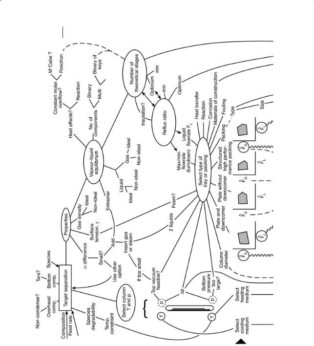
Figure 4.1 Sizing map for distillation.

94 4 Homogeneous Separation
top of the column), azeotropic distillation (solvent is added to the feed to the column), HIGEE (unique spinning tray design) and reactive (reaction and distillation are combined, for example for selective catalytic hydrogenation of C4 to C6, Section 6.35). The operation can be batch or continuous.
The internals are usually trays, random packing or structured packing.
x Guidelines
Distillation is usually the first choice for homogeneous separation ($).
The issues for sizing distillation columns, and the types of internals, are summarized in Fig. 4.1.
Prefer to remove the most valuable as distillate ($,C). Prefer to remove components one by one as overhead ($,C). Prefer separations that give equimolar splits ($).
Set the column pressure to try to use water as the coolant and steam as the energy source ($).
Overhead concentrations 95–99 % mol (J).
In selecting the internals: for ordinary distillation at I 100 kPa, select (i) structured packing, (ii) random packing. For distillation at 0.1–0.4 MPa, use foaming, fouling and $ as criteria. For distillation at i 0.4 MPa select (i) trays.
Qualitatively:
Trays: high pressure drop/HETS, high liquid holdup, low liquid/vapor ratio, can handle some fouling, high liquid loads, use care if foams, relatively high HETS, $ low.
Random packing: medium pressure drop/HETS, medium liquid holdup, wide range in liquid/vapor ratio, not for fouling, high vapor loads, OK for foams, medium HETS, $ medium. Use for columns I 1 m diameter; OK for viscous liquids. Structured packing: low pressure drop/HETS, low liquid holdup, not for fouling, high vapor loads, OK for foams, low HETS, $ high. Not for viscosities i 2 mPa s, pressures i 200 kPa.
A general comparison of the properties, relative to other gas–liquid contact devices is given in Table 1.1, Section 1.6.1.
x If trays are selected, then calculate the number of theoretical stages, NTS, required.
Tray options: valve: usually cheaper than sieve, use for large diameter columns at moderate to high pressures, moderate turndown ratio. Usually about 120 to 140 valves per active m2.
sieve: use for large diameter columns at moderate to high pressures, moderate turndown ratio, residence time for sieve tray plus downcomer 2–20 s. Dp/HETS = 0.4–1 kPa; HETS = 0.6–1.2 m.
bubble cap: use for columns with small liquid flowrate, high turndown ratio, heat transfer needed internally. Residence time 20–30 s.
Downcomer: unaerated liquid velocity 0.5 m/s; head loss via underflow clearance I 0.3 kPa. Allow 3 s liquid residence time and extend to 6 s for foaming systems. Weir overflow velocity = 5–20 L/s m of outlet weir.

4.2 Distillation 95
x If packings are selected, then calculate the number of transfer units, NTU, required or number of theoretical stages (NTS).
–conventional random dumped packings: Pall rings, Tellerettes, raschig rings, beryl or intalox saddles, lessing rings. Prefer Pall rings and Tellerettes; if ceramic, use saddles. Usually use 5 cm diameter slotted rings for vapor flowrates i 950 dm3/s; use 2.5 cm or smaller for vapor flowrates I 230 dm3/s. Dp/HETS = 0.15–0.3 kPa. Dp/m of packing = 0.08–0.65 kPa/m or 0.32–0.65 kPa/m for moderate to high pressure distillation and 0.08–0.16 kPa/m for vacuum operation. HETS: HETS = 0.4–1.5 m; HETS 0.45–0.8 m for small diameter columns; 0.60–1.1m for i 1 m diameter.
–high performance structured packing: Hypac, Flexipac, Gauze, Glitsch grid, Leva film:
Dp/HETS = 0.001–0.5 kPa; very small superficial gas velocity. HETS = 0.1–0.8 m.
To estimate the NTS, number of theoretical stages:
1. Estimate minimum reflux ratio from the Underwood equation, or as an approximation if the distillate is almost pure:
1
Rmin = (a – 1)(xLK,Feed)
Select operating reflux ratio at 1.2 to 1.5 times minimum ($). For vacuum distillation, usually the reflux ratio is i 10:1 especially for packed columns.
2. Estimate the minimum number of theoretical stages using the Fenske equation, or as approximations:
Douglas’s, T = absolute temperature for overhead distillate, D, and for the bottoms, W.
TD + TW |
|
Nm = 3(TW – TD) |
|
Latour’s: x = mol fraction. |
|
Nm = 0.11 TW – TD log10 |
xW(1 – xD) |
TD + TW |
xD(1 – xW) |
The number of theoretical trays = twice the minimum number, Nm.
3. For trays: estimate the actual number of trays using the following tray efficiencies:
–Sieve, valve, or plate trays, tray efficiency 60 % (F); pressure drop 0.7 to 1.4 kPa/ tray or 0.3–0.65 kPa/theoretical stage. HETS = tray spacing/tray efficiency, usually = 0.6/0.6 = 1 m. The usual range is 0.6–1.2 m.
–Sieve, valve, or plate trays, the tray efficiency decreases as the viscosity of the liquid (at column conditions) increases; at 0.2 mPa s, tray efficiency = 60 %; at 1 mPa s, tray efficiency = 16 % (F).

964 Homogeneous Separation
4.For trays: estimate the column height by the number of actual trays q 0.6 m tray spacing plus 1.2 m at the top and 1.8 m at the bottom.
5.For trays: estimate the column diameter with trays assume acceptable superficial vapor velocity
0.3m/s for high pressure operation
0.9 m/s for atmospheric operation
2.5 m/s for vacuum I 13 kPa.
or superficial density-weighted vapor flowrate, F factor, of 1.2 to 1.4 m/s (kg/m3)0.5 or boilup rate = 1.35 kg/s m2. The superficial gas velocity = F/(vapor density)0.5
The superficial, density-weighted vapor velocity, “k”, is used to size the diameter of distillation columns, absorbers, Section 4. 8, gas–liquid separators or knock out pots, Section 5.1, and face velocity to demisters, Section 9.1. For convenience, values of “k” are given in Table 4.1 for different applications.
L/D I 30; maximum height 55 m limited by windload.
Tray column without downcomers: superficial gas velocity 0.5–3 m/s; kL 0.01– 0.04 m/s; area/unit volume 100–200 m2/m3; kL a = 1–8 1/s; liquid holdup = 0.5–0.7.
Table 4.1 Density-weighted vapor flowrate or “capacity factor”, m/s, for different types of separations and contacting
Type of contacting |
Value of “k”, m/s |
Value of F factor; |
Comment |
|
|
m/s (kg/m3)0.5 |
|
|
|
|
|
Distillation: trays |
0.025–0.06 usual |
1.2–1.8; 0.3–2.5 |
|
|
0–0.15 |
|
|
|
0.009–0.075 “typical” |
|
|
Distillation: |
0.009–0.09 “typical” |
0.6–3.5; 0.3–2.9 |
|
random packing |
|
|
|
Distillation: |
0.003–0.14 “typical” |
0.5–2.5; 0.12–4.4 |
|
structured packing |
|
|
|
Absorption, trays |
|
1.2–1.8 |
with allowance of 1.5 m space above top tray |
Absorption, |
0.051 |
0.6–3.5 |
|
random packing |
|
|
|
Knock out pots |
0.03 to 0.12 with the |
|
usual value 0.07–0.09. |
For horizontal vessels, higher values of k can be used. Use smaller values of k when the drop size in the mist is expected to be smaller.
Demister |
0.06–0.12 with usual |
|
|
0.106 |
|
|
0.106 |
for operating pressure 0.7 MPa and “k” |
|
|
decreases by 0.003 for each increase in |
pressure by 0.7 MPa. Application: knock out pot + demister on suction of compressor for natural gas.

4.2 Distillation 97
3. For packing: estimate the height of packing from the NTU q HTU (or NTS q HETS). For distillation HTU z HETS because mass transfer resistance is in the gas phase, or kL/kG i i 1.
For conventional dumped packing: column diameter/packing diameter i 15; use 2.5 cm packing for gas flowrates about 250 dm3/s; use 5 cm diameter packing for gas flowrates i 1000 dm3/s;
In general HETS = 0.3 to 1.8 m; 2.5 cm Pall rings: HETS = 0.4 to 0.8 m; 5 cm Pall rings, HETS = 0.7 to 0.9 m.
Split total height into self-supported sections: plastic packings: 3 to 4.5 m max. height to prevent weight from collapsing the packing; metal packings: 6 to 7.5 m height max.
Use liquid distributors every 5 to 10 tower diameters of height with at least one every 6 m. Distributors have 30 to 50 discharge nozzles/m2 for diameters I 1 m.
5. For packing: estimate the column diameter: for conventional random packing: acceptable superficial vapor velocity, expressed as a percentage of gas flooding velocity is for intalox saddles, 80 % of flooding; surface areas 50 to 700 m2/m3 with increasing values as the diameter decreases.
for raschig rings 60 % of flooding. for Pall rings 90 % of flooding.
or 1.4 to 2.2 m/s or superficial gas density-weighted velocity, F, of 0.6 to 3.5 m/s (kg/m3)0.5.
Superficial mass ratio weighted velocity for flooding = 0.35 m/s.
The liquid loading must be sufficient to wet the packing; which is 0.015 to 4 kg/ s m of wetted periphery of the packing (0.015 to 4 L/s m ) or superficial liquid loading of 3 to 35 L/m2 s . Must be at least 0.5 L/m2 s. If there is insufficient liquid, then increase the size of packing to reduce the area per unit volume.
Flooding at the density ratio weighted superficial vapor velocity, “k”, of 0.1 m/s. Dp for moderate to high pressure 0.3–0.6 kPa/m packing height; for vacuum
0.08–0.16 kPa/m and see Section 2.1.
HETS |
|
|
packing size, cm |
HETS, m |
|
2.5 |
0.46 |
(vacuum operation, 0.67) |
3.8 |
0.67 |
(vacuum operation, 0.82) |
5 |
0.91 |
(vacuum operation, 1.06) |
Packed column: superficial gas velocity 0.1–1 m/s; kL 0.003–0.02 m/s; area/unit volume 20–350 m2/m3; kLa = 0.06–7 1/s; liquid holdup = 0.05–0.1.
If structured packing is selected; design for 70 to 80 % of flooding; for foaming use 40 % of flooding. Usual liquid flowrate of 0.007 to 5 L/s m2. Usual gas den- sity-weighted superficial velocity of 0.5 to 2.5 m/s (kg/m3)0.5. Dp/HETS = 0.01 to 0.05 kPa. If the Dp i 1.2 to 1.6 kPa/m, then the packing is flooded. HETS 0.12 to 0.45 m. with this increasing to 1.8 m for high liquid capacity Glitsch grid. “k” or density-weighted velocity = 0.3 m/s for flexigrid structured packing; = 0.5 m/s for structured packing.

98 4 Homogeneous Separation
For extractive distillation, the solvent should have a boiling temperature 50 to 100 hC higher than those of the products with solubility parameters and molar volume similar to those of one product but different from the other. Related additional units include decanters, Section 5.3.1 and strippers, Section 4. 9.
For azeotropic distillation, additional units include decanters (see Section 5.3.1) and strippers, Section 4.9.
For molecular distillation, 0.2 to 0.5 g/s m2 with about 4.5 m2/unit. 80 to 90 % efficient.
For steam distillation, for direct heating 25 to 120 kg/m3. For inert steam added, flowrate calculated.
For HIGEE, residence time 0.1–1 s; voidage 90–95 %; 2 m diameter max., area per volume 2000–5000 m2/m3. 1000 rpm; film thickness 100 mm. Overall heat transfer coefficient U = 10 kW/m2 K. See also Reactive distillation, Section 6.35.
For batch distillation, size based on cycle time: fill, distill, discharge bottoms, clean.
for avp = 2, NTS = 10; reflux ratio 20:1 avp = 4, NTS = 6; reflux ratio 12:1
avp = 10, NTS = 3; reflux ratio 7.5:1 To convert TS to height of packing
1 TS = 1 m of i 5 cm dumped Pall rings or saddles 1 TS = 0.9 m of 4 cm dumped Pall rings or saddles
1 TS = 0.6 m of I 2.5 cm dumped Pall rings or saddles
1 TS = 0.15 m of structured mesh packing in column of diameter I 0.3 m 1 TS = 0.3 m of structured mesh packing in column of diameter i 0.3 m as the
more volatile species is removed, the separation becomes progressively more difficult.
too low a reflux gives unattainable product regardless of the number of trays. gives high purity recovery from a small concentration of a low boiling species in
a single operation.
keep the reflux holdup I 10 to 15 % of the initial batch charge.
x Good Practice
Prefer the use of low holdup internals or HIGEE (H). Prefer a distillation sequence to minimize inventory of hazardous material (H). Select materials of construction to promote wetting: select critical surface tension of the solid to be i the surface tension of the liquid. If the surface tension of the distillate i surface tension of the bottoms (surface tension negative) prefer the use of trays to packings to minimize potential for liquid film breakup. If the surface tension of the distillate I surface tension of the bottoms (surface tension positive), the foam above trays might be unexpectedly stable.
For trays, add 10 % more trays or two trays to improve operability. Weir height: 5 cm with length 75 % of the tray diameter to provide a liquid weir overflow rate i 5 and I 20 L/s m of weir into the downcomer. Usually use 15 L/s m, For lower flows use a picket weir. Overall downcomer area should be i 5 % total tray area. For foaming liquids increase downcomer area by 50 %.The downcomer exit

4.2 Distillation 99
should be at least 1.2 cm below the top edge of the outlet weir. Include four, 6 mm diameter weep holes in each tray for shutdown drainage. For packing, water test the liquid distributor for good liquid distribution before startup.
x Trouble Shooting
The relationship between the symptom and the causes partly depends on the control system used. Check the auxiliaries to see if they are at fault: reboilers and condensers, see Sections 3.2 and 3.3; vacuum, see Section 2.2; pumps, see Section
2.3. For packed towers, 80 % of the causes are liquid maldistribution. |
|
|
“Dp across the column |
i i design (i half the column height), reflux |
flowrate |
i i usual; DT across |
column I design, overhead composition contains |
heavies |
i design; surges in the liquid overhead, bottoms level low or fluctuates, bottoms pressure i design, higher column pressure and higher temperature profile below the flooded portion of the column the temperature profile i design and “all trays below the flood are dry” and bottoms composition off spec“: [ jet flooding]*.
“Dp across the column i i design, reflux flowrate gradually increasing; DT across column I design, overhead composition contains heavies i design; bottoms level low or fluctuates, bottoms pressure i design, and higher temperature profile below the flooded portion of the column the temperature profile i design and “all trays below the flood are dry”: [downcomer flooding]*.
“Dp across the column i design”: instrument fault/high boilup rate/steam flow to reboiler i design.
“Dp across the column I design”: instrument fault/[low boilup rate]*, see Section 3.3/dry trays/low feedrate/feed temperature too high.
“Feed flowrate I design”: instrument fault/pump problems, see Section 2.3/filter plugged/column pressure i design/feed location higher than design. “Temperature of feed i design”: instrument fault/preheater fouled/feed flowrate low/heating medium temperature I design, see heaters, Section 3.3. “Temperature of bottoms I design”: instrument fault/[low boilup]* see Section 3.3/ loss of heating medium/steam trap plugged, see Section 5.1/feed rate to column i design/feed concentration of low boilers (overheads) i design/feed distributor fouled.
“Temperature of bottoms i design”: instrument fault/[column pressure i design]*/ high boilup/overhead condenser vent plugged/insufficient condensing, see Section 3.3.
“Temperature at top i design”: instrument fault/bottom temperature i design/reflux too low/distillate feed forward too high/column pressure high/[ flooding]*.
“Temperature at top i design and overhead composition contaminated with too many heavies”: vapor bypassing caused by excessive vapor velocities (high boilup) or not enough liquid on tray or packing, or downcomers not sealed, or sieve holes corroded larger than design and tray weeps/reflux too low/feed contains excessive heavies.
“Temperature at top I design”: instrument fault/control temperature too low/[low boilup]* see Section 3.3.
“All temperatures falling simultaneously”: [low boilup]*.

100 4 Homogeneous Separation
“All temperatures rising simultaneously:” pressure rising.
“Overhead off spec”: poor tray or packing efficiency/liquid maldistribution (weirs not level, low liquid load and backmixing/not enough trays or packing/loss of efficiency/high concentration of non-condensibles/missing tray/collapsed tray/liquid entrainment/liquid bypass and weeping/liquid or gas maldistribution/excessive inerts from upstream/buildup of trace/purge not sufficient from recycle.
“Overhead contaminated with heavies and excessive reflux rate and high boilup rate”: inadequate gas-liquid contact/insufficient liquid disengagement from vapor/presence of noncondensibles in feed. “Overhead and bottoms off spec and decreases across column in both DT and Dp ”: [dry trays]*.
“Overhead and bottoms off spec”: bypass open on reflux control valve. “Overhead and bottoms off spec, decrease in DT across column and perhaps Dp increase and cycling of liquid in the bottoms”: [damaged tray]*. “Level of bottoms i design”: bottoms pump failure, see Section 2.3/bottoms line plugged. and see implications for reboiler, Section 3.3. “Level in bottoms i design” and [column pressure i design]*/high boilup/overhead condenser vent plugged. “Level in bottoms i design and pressure increase in kettle reboiler and surges“: foaming, inerts/leaks in kettle reboiler/undersized reboiler. See also Section 3.3. “Bottoms off spec”: loss of tray efficiency/contamination of bottoms from pump (from light oil lubricant in bottoms pump or forced circulation reboiler)/transient vapor puff from horizontal thermosyphon reboiler, see Section 3.3. “Distillate flow too low”: feed rate low/feed composition of overhead species low/[low boilup]*/reflux too high/overhead control temperature too low. “Bottoms and overhead flowrates I design”: [ flooding]*/excessive entrainment/[ foaming]*/excessive Dp but not flooded/plugging and fouling/liquid maldistribution. “Distillate flow too high:” feedrate high/feed composition of overhead species high/reflux ratio too low. “Water hammer in column”: process fluid above the tube sheet of a thermosyphon reboiler. “Cycling of column temperatures:” controller fault. “Product contamination”: leaking valves/crud left in storage tanks/ crud left in dead legs in piping/corrosion products/unexpected chemical reactions/sampling fault/analysis fault/unexpected solubility effects. “Separation performance of column decreases”: trace amounts of water/trace amounts of water trapped in column/[bumping resulting in tray damage]*.
“Cycling (30 s – several minutes duration) steam flow, cycling pressure on the process side and, for columns, cycling Dp and cycling level in bottoms”: instrument fault/condensate in instrument sensing lines/surging/[ foaming]* in kettle and thermosyphon/liquid maldistribution/steam trap problems, see Section 5.1, with orifice Dp across trap I design/temperature sensor at the feed zone in a distillation column/collapsed tray in a distillation column.
[Bumping resulting in tray damage]*: trace amounts of water.
[Column pressure i design]*: [high boilup]*/overhead condenser vent plugged. [Damaged trays]*: leak of water into high molar mass process fluid/large slugs of water from leaking condensers or steam reboilers/startup with level in bottoms i design/attempt to overcome flooding by pumping out bottoms at high rate/ too rapid a depressurization of column/unexpected change in phase.