


Ä |
|
2.2/2.5L ENGINES 9 - 47 |
|
(5)Turn crankshaft until number one cylinder is at Top Dead Center (TDC). The timing marks on the chain sprocket should line up with the parting line on the left side of number one main bearing cap. (Fig. 21).
(6)Place chain over crankshaft sprocket so that the nickel plated link of the chain is over the timing mark on the crankshaft sprocket (Fig. 21).
(7)Place balance shaft sprocket into the timing chain (Fig. 17) so that the timing mark on the sprocket (yellow dot) mates with the (lower) nickel plated link on the chain.
(8)With balance shaft keyways pointing up (12 o'clock) slide the balance shaft sprocket onto the nose of the balance shaft. The balance shaft may have to be pushed in slightly to allow for clearance.
Fig. 21 Balance Shaft Timing
THE TIMING MARK ON THE SPROCKET, THE (LOWER) NICKEL PLATED LINK, AND THE ARROW ON THE SIDE OF THE GEAR COVER SHOULD LINE UP WHEN THE BALANCE SHAFTS ARE TIMED CORRECTLY.
(9) If the sprockets are timed correctly install the balance shaft bolts and tighten to 28 Nzm (250 in. lbs.). A wood block placed between crankcase and crankshaft counterbalance will prevent crankshaft and gear rotation.
CHAIN TENSIONING
(1)Install chain tensioner loosely assembled.
(2)Position guide on double ended stud making sure tab on the guide fits into slot on the gear cover. Install and tighten nut/washer assembly to 12 Nzm (105 in. lbs.).
(3)Place a shim 1mm (.039 inch) thick x 70mm (2.75 inch) long or between tensioner and chain. Push tensioner and shim up against the chain. Apply firm pressure (5.5 to 6.6 lbs.) directly behind the adjustment slot to take up all slack (chain must have shoe radius contact as shown in Fig. 22).
(4)With the load applied, tighten top tensioner bolt first, then bottom pivot bolt. Tighten bolts to 12 Nzm (105 in. lbs.), Remove shim.
(5)Install carrier covers and tighten screws to 12 Nzm (105 in. lbs.).
Fig. 22 Chain Tensioner Adjustment
INTERMEDIATE SHAFT SERVICE
REMOVAL
CAUTION: The oil pump and distributor must be removed before attempting to remove intermediate shaft.
(1)Hold sprocket with Tool C-4687 and adaptor Tool C-4687-1 when removing or installing screw (Fig. 23).
(2)See Timing System and Seals for intermediate seal removal and replacement.
(3)Remove retainer screws (Fig. 24).
(4)Remove retainer and lay aside.
(5)Remove intermediate shaft.

9 - 48 2.2/2.5L ENGINES |
|
Ä |
|
Fig. 23 Removing/Installing Intermediate Shaft
Sprocket
Fig. 24 Intermediate Shaft Retainer
Fig. 25 Intermediate Shaft Retainer Sealing
INSTALLATION
(1)Lubricate distributor drive gear when install-
ing.
(2)Apply Mopar Gasket Maker as shown in (Fig.
25)and install intermediate shaft retainer.
Fig. 26 Intermediate Shaft Bushing, Front
Fig. 27 Intermediate Shaft Bushing−Rear
Fig. 28 Intermediate Shaft Journal Specifications
(3) Install retaining screws and torque to 12 Nzm (105 in. lbs.).
INTERMEDIATE SHAFT BUSHING SERVICE
(1)Remove front bushing using Special Tool C-4697-2 with Special Tool Handle C-4171 (Fig.26).
(2)Install front bushing using Special Tool C-4697-1 and Special Tool Handle C-4171 until tool is flush with block.
(3)Remove rear bushing using Special Tool C-4686-2 and Special Tool Handle C-4171 (Fig. 27).
(4)Install rear bushing using Special Tool C-4686-1 and Special Tool Handle C-4171 until tool is flush with block.
Ä |
|
2.2/2.5L ENGINES 9 - 49 |
|
CYLINDER BLOCK, PISTON AND CONNECTING
ROD ASSEMBLY SERVICE
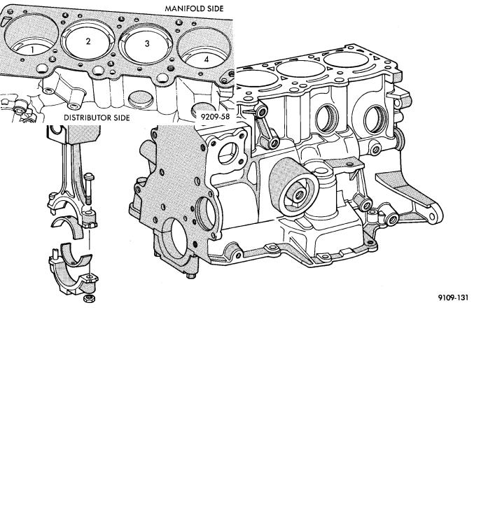
Fig. 1 Cylinder Block, Piston and Connecting Rod Assembly
PISTON AND CONNECTOING ROD−REMOVAL
(1) Remove top ridge of cylinder bores with a reliable ridge reamer before removing pistons from cylinder block. Be sure to keep tops of pistons covered during this operation. Mark piston with matching cylinder number (Fig. 2).
Fig. 2 Piston Marking
(2)Remove oil pan. Ensure connecting rods and connecting rod caps for cylinder identification. Identify them if necessary (Fig. 3).
(3)Valve relief toward manifold side of engine. Turbocharged engine pistons will have arrow towards front of engine.
Fig. 3 Identify Connecting Rod to Cylinder
(4)Squirt hole on connecting rod must face timing belt end of engine.
(5)Pistons and connecting rods must be removed from top of cylinder block. Rotate crankshaft so that each connecting rod is centered in cylinder bore.
(6)Remove connecting rod cap. Install connecting rod bolt protectors on connecting rod bolts (Fig. 4). Push each piston and rod assembly out of cylinder bore.
Be careful not to nick crankshaft journals.
(7)After removal, install bearing cap on the mating
rod.

9 - 50 2.2/2.5L ENGINES |
|
Ä |
|
Fig. 4 Connecting Rod Protectors
CYLINDER BLOCK CLEANING AND
INSPECTION
(1)Clean cylinder block thoroughly and check all core hole plugs for evidence of leaking.
(2)If new core plugs are installed, Refer to Engine Core Oil and Cam Plugs.
(3)Examine block and cylinder bores for cracks or fractures.
CYLINDER BORE INSPECTION
The cylinder walls should be checked for out-of- round and taper with Tool C-119 (Fig. 5). The cylinder bore out-of-round is 0.050 mm (.002 inch) maximum and cylinder bore taper is .125 mm (.005 inch) maximum. If the cylinder walls are badly scuffed or scored, the cylinder block should be rebored and honed, and new pistons and rings fitted. Whatever type of boring equipment is used, boring and honing operation should be closely coordinated with the fitting of pistons and rings in order that specified clearances may be maintained. Refer to Honing Cylin-
Fig. 5 Checking Cylinder Bore Size
der Bores outlined in the Standard Service Procedures for specification and procedures.
Measure the cylinder bore at three levels in directions A and B (Fig. 5). Top measurement should be 10mm (3/8 inch.) down and bottom measurement should be 10mm (3/8 inch.) up from bottom of bore. Refer to (Fig. 6) for specifications.
SIZING PISTONS
Piston and cylinder wall must be clean and dry. Piston diameter should be measured 90 degrees to piston pin at size location shown in (Fig. 7). Cylinder bores should be measured halfway down the cylinder bore and transverse to the engine crankshaft center line shown in (Fig. 5). Refer to (Fig. 6) for specifica-
Fig. 6 Piston Size Location and Clearance Chart
Ä |
|
2.2/2.5L ENGINES 9 - 51 |
|
Fig. 7 Piston Installation and Sizing Information
Fig. 8 N.A. (Naturally Aspirated) Pistons
tions. Correct piston to bore clearance must be established in order to assure quiet and economical operation.
Fig. 9 2.2L Turbo III and 2.5L Turbo I Pistons
Chrysler engines use pistons designed specifically for each engine model. Clearance and sizing locations vary with respect to engine model.
Pistons and cylinder bores should be measured at normal room temperature, 70°F. (21°C).
Fig. 10 Piston Pin Lock Ring Removal
Notch−Turbocharged Engine