

If you want help about Do this
A particular topic From the Help Topics dialog box, click the
Index tab.
A form or field On the Aspen Plus toolbar, click the What’s
This button then click the field or form.
A dialog box Click the Help button on the dialog box.
The item the cursor or
mouse pointer is on Press F1.
Keeping Help On Top
To keep the Help window on top of any other open windows:
1 In the Help window, click the Options button or menu.
2 Point to Keep Help On Top, and then click On Top.
Using the Back Button
Use the Back button to move back through help screens you have seen. If there is no previous topic to view, the Back button is unavailable. Back keeps a complete record of all the help topics
you view. This list is cleared each time you exit help.
Searching for Help on a Topic
You can find specific information quickly by searching for it. To
search for a topic or keyword:
1 From the Help menu, click Help Topics, then From the Help
Topics dialog box, click the Index tab.
The Index dialog box appears.
2 Start typing a word or phrase to display a list of index entries
that match what you are looking for.
3 Click Display or double-click on the entry in the list. Either the topic appears, or a dialog box containing a list of topics appears.
Displaying Help on Dialog Boxes,
Forms and Sheets
To access online Help that gives you an overview of a dialog box, form or sheet:
Click the Help button on the dialog box, form or sheet.
– or –
Press F1 on the dialog box, form or sheet.
Displaying Help on Screen Elements
To access online Help on buttons, fields, commands on menus, and similar screen elements:
Click the What's This button on the window toolbar and then click the element.
– or –
Select
the element, then press F1
![]() or
or![]()
Getting Step by Step Help
To get help on preparing, specifying, and running simulations, and reviewing results:
1 From the Help Topics dialog box, click the Contents tab.
2 Double-click Using Aspen Plus, then click the topic you want.
Getting Reference Information
To obtain reference information:
From the Help Topics dialog box, click the Contents tab, then
click the appropriate topic.
Getting Printed Information
You can:
Print help topics
Obtain printed Aspen Plus documentation
Printing Help
To print a help topic:
1 Make sure the printer settings are correct.
To check this, Click Start, then point to Settings then Printers.
2 Display the Help topic you want to print.
3 Click the Print button.
– or –
Click the Options button, then click Print Topic.
– or –
From the File menu, click Print Topic.
Printing Popup Help
To print popup help windows:
1 Click with the right mouse button on the Help window.
2 From the popup menu, click Print Topic.
Getting Printed Documentation
You can print all of the Aspen Plus manuals from the Documentation CD supplied with Aspen Plus. The manuals are available in Adobe portable document format (.pdf).
The Aspen Plus documentation set is listed below:
Aspen Plus Installation Guide for Windows This guide provides instructions on installation of Aspen Plus.
Aspen Plus Getting Started Building and Running a Process Model
This tutorial includes several hands-on sessions to familiarize you with Aspen Plus. The guide takes you step-by-step to learn the full power and scope of Aspen Plus. Aspen Plus Getting Started Modeling Processes with Electrolytes This tutorial includes several hands-on sessions to familiarize you with simulating electrolyte systems with Aspen Plus. Aspen Plus Getting Started Modeling Petroleum Processes This tutorial includes several hands-on sessions to familiarize you with simulating petroleum processes with Aspen Plus. Aspen Plus Getting Started Customizing Unit Operation ModelsThis tutorial includes several hands-on sessions to familiarize you with the customization of unit operation models with Aspen Plus.
Aspen Plus Reference Manuals The Aspen Plus reference manuals provide detailed technical reference information. The manuals include background information about the unit operation models, available physical properties methods and models, tables of Aspen Plus databank parameters, equations, and a wide range of other reference information. The set comprises:
Unit Operation Models
User Models
System Management
System Administration Guide
Summary File Toolkit
Input Language Guide
Linking to Aspen Tech Home Page
For additional information about AspenTech products and services, check the AspenTech World Wide Web home page on the Internet
at:
http://www.aspentech.com/
Contacting Aspen Plus Technical
Support
AspenTech customers with a valid license and software maintenance agreement can register to access the Online Technical Support Center at http://support.aspentech.com/
This web support site allows you to:
Access current product documentation
Creating a Process Flowsheet
To define a process flowsheet:
1 From the View menu, ensure that PFD mode is turned off.
Otherwise, the blocks and streams you place graphically, do
not become part of your simulation model.
2 Select the unit operation blocks and place them in the Process
Flowsheet Window.
3 Connect the streams to the blocks.
After placing blocks and streams, you can:
Delete blocks and streams
Rename the blocks and streams
Change stream connections
You can also improve the appearance of your flowsheet in many
different ways. For more information, see Modifying the
Flowsheet.
Mouse Pointer Shapes
When you are defining your flowsheet, the shape of the mouse pointer changes, indicating the particular mode Aspen Plus is in:
|
Pointer Shape
|
Function |
Use
|
|
|
Select mode |
Click an object to select it. Click and hold an object to enter Move mode. Click and drag to select a region or to move or resize a region (The pointer changes to the Resize shape). Insert mode Click to place a model of the type selected in the |
|
|
Insert mode |
Click to place a model of the type selected in the Model Library Note After placing each block, you remain in Insert Mode until you click the Select Mode button
Library. |
|
|
Connect mode |
Click a port to connect the stream to it Click a blank area of the flowsheet to to place a feed or product |
|
|
Move mode |
Click and hold to move the port to a desired location |
|
|
Port move mode |
Click and hold to move the port to a desired location Drag the port away from the model to enter Disconnect mode |
|
|
Disconnect mode |
Click and hold on a stream while dragging it away from a block to disconnect it. Release the mouse button to enter Connect mode |
|
|
Resize mode |
Click and drag to resize a model or region |
Placing Blocks
To place a unit operation block in a simulation flowsheet:
1 Click a model category tab in the Model Library to display a list of models in that category.
2 In the Model Library, select the unit operation model that you want to place in your process flowsheet. To choose a different icon for the model, click the down arrow, and click an icon to select it. The icon you select will remain the default icon when placing that model, until you change the icon.
3 Click and hold down the mouse button on the unit operation model, and drag it to the Process Flowsheet window.
4 The mouse pointer is in the shape of a box with an arrow, which indicates that only one block will be placed.
5 In the Process Flowsheet window, release the mouse button
where you want to place the block.
If you have switched off Automatically Assign Block Names, you are prompted to enter the Block ID. For more information on IDs, see Options for Naming Blocks and Streams. The icon
that you selected appears on the flowsheet.
6 Continue creating your flowsheet. To place another block repeat steps 1 through 4.
When you place or move blocks, the center of the block icon snaps to a grid location if Snap to Grid is enabled on the Grid/Scale tab of the Tools Options dialog box.
Placing Multiple Blocks
To place multiple blocks of the same type in the flowsheet:
1 Click a model category tab in the Model Library to display a list of models in that category.
2 In the Model Library, select the unit operation model that you want to place in your process flowsheet. To choose a different icon for the model, click the down arrow, and click an icon to
select it. The icon you select will remain the default icon when placing that model, until you change the icon.
3 Click the unit operation model (click the icon then release the mouse button.)
The pointer appears in the shape of a crosshair, representing Insert mode.
4 In the Process Flowsheet window, click where you want to place the block. The icon that you selected appears on the If you have switched off Automatically Assign Block Names,
you are prompted to enter the Block ID. For more information on IDs, see Options for Naming Blocks and Streams. The icon that you selected appears on the flowsheet.
5 Continue creating your flowsheet
|
If you want to |
Do this |
|
Place another block for the same model |
Click in a new location on the flowsheet |
|
Place a block for a different model |
Repeat steps 1 to 4. |
|
Stop placing blocks |
Click
the Select Mode button
|
When you place or move blocks, the center of the block icon snaps to a grid location if Snap to Grid is enabled on the Grid/Scale tab of the Tools Options dialog box.
Placing Streams and Connecting Blocks
To place a stream:
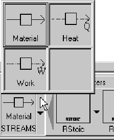
1 Click the STREAMS icon on the left side of the Model Library.
2 If you want to select a different stream type (Material, Heat or Work), click the down arrow next to the icon and choose a different type.
Move the mouse pointer to the Process Flowsheet window. For each block in the Process Flowsheet window, all ports that are compatible with that stream type are highlighted Ports.
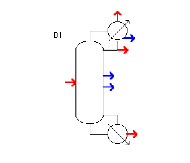
Ports that must have at least one stream connected are shown in red. Other optional ports are shown in blue. If you position the mouse over a displayed port, the arrow is highlighted and a text box with the description of the port appears.
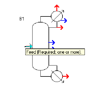
3 Click a highlighted port to make the connection.
If
the port is not at the location you want it, click and hold the mouse
button on the port. When the mouse pointer changes to the port move
shape
![]() drag to relocate the port on the icon.
drag to relocate the port on the icon.
4 Repeat step 4 to connect the other end of the stream. Only those ports that you can connect the other end of the stream to remain highlighted. For example, if you connect a stream to an outlet port, inlet ports remain highlighted but outlet ports are no longer highlighted.
If you have switched off Automatically Assign Stream Names, then you will be prompted for a Stream ID.
5 To place one end of the stream as either a process flowsheet feed or product, click a blank part of the Process Flowsheet window.
If the stream’s source is already connected, then a product will be placed. If the stream’s destination is already connected, then a feed will be placed. By default, if you click a blank part of the window before connecting either stream end, a feed is placed.
6 To stop
placing streams click the Select Mode button![]() in the upper left corner of the Model Library:
in the upper left corner of the Model Library:
To cancel connecting the stream at any time, press ESC or click the right mouse button.
To place another stream of the same type, repeat steps 4 through 6.
To place a stream of a different type, repeat steps 2 through 6.
Placing Streams and Connecting Blocks Using Drag and Drop
You can also use drag and drop to connect streams. The procedure is similar to the one described above.
1 Select the stream type you want, by clicking the Material Stream icon in the Model Library or using the down arrow next to the icon to select a Heat or Work stream.
2 Click and hold down the mouse button on the stream icon.
3 Move the cursor to the Process Flowsheet Window.
The compatible ports are highlighted.
4 Release the mouse button on:
A port to make a connection
A blank part of the flowsheet to place a feed
5 Move the mouse and click:
Another highlighted port to connect the other end of the
stream
A blank part of the flowsheet to place a product
Using Heat and Work Streams
You can define heat and work streams to transfer heat and power between blocks, or for duty and power specifications. For example, you can use a work stream to transfer power from a turbine to a compressor.
When creating a heat or work stream:
Select the heat or work icon from the Model Library.
Use a port labeled Heat Stream(s) or Work Streams(s).
Heat and work streams appear as dashed lines in the flowsheet.
Using PseudoProduct Streams
You can define pseudoproduct streams to represent column internal flows, compositions, thermodynamic conditions streams for some unit operations models.
Pseudoproduct streams from one block may be an inlet to another block. Using a pseudo-stream as a block inlet results in an imbalance in the overall flowsheet material and energy balance
report.
To define a pseudoproduct stream:
When creating the stream select a port labeled Pseudo Streams.