

Advanced Wireless Networks - 4G Technologies
.pdfPreface
The major expectation from the fourth generation (4G) of wireless communication networks is to be able to handle much higher data rates, which will be in the range of 1Gb in the WLAN environment and 100 Mb in cellular networks. A user, with a large range of mobility, will access the network and will be able to seamlessly reconnect to different networks, even within the same session. The spectra allocation is expected to be more flexible, and even flexible spectra sharing among the different subnetworks is anticipated. In such a ‘composite radio environment’ (CRE), there will be a need for more adaptive and reconfigurable solutions on all layers in the network. For this reason the first part of the book deals with adaptive link, MAC, network and TCP layers including a chapter on crosslayer optimization. This is followed by chapters on mobility management and adaptive radio resource management. The composite radio environment will include presence of WLAN, cellular mobile networks, digital video broadcasting, satellite, mobile ad hoc and sensor networks.
Two additional chapters on ad hoc and sensor networks should help the reader understand the main problems and available solutions in these fields. The above chapters are followed by a chapter on security, which is a very important segment of wireless networks.
Within the more advanced solutions, the chapter on active networks covers topics like programmable networks, reference models, evolution to 4G wireless networks, 4G mobile network architecture, cognitive packet networks, the random neural networks based algorithms, game theory models in cognitive radio networks, cognitive radio networks as a game and biologically inspired networks, including bionet architecture.
Among other topics, the chapter on networks management includes self-organization in 4G networks, mobile agent-based network management, mobile agent platform, mobile agents in multioperator networks, integration of routing algorithm and mobile agents and ad hoc network management.
Network information theory has become an important segment of the research, and the chapter covering this topic includes effective capacity of advanced cellular network, capacity of ad hoc networks, information theory and network architectures, cooperative transmission in wireless multihop ad hoc networks, network coding, capacity of wireless networks using
xx PREFACE
MIMO technology and capacity of sensor networks with many-to-one transmissions. Two additional chapters, energy efficient wireless networks and QoS management, are also included in the book.
As an extra resource a significant amount of material is available on the book’s companion website at www.wiley.com/go/glisic in the form of three comprehensive appendices: Appendix A provides a review of the protocol stacks for the most important existing wireless networks, Appendix B presents a comprehensive review of results for the MAC layer and Appendix C provides an introduction to queueing theory.
The material included in this book is a result of the collective effort of researchers across the globe. Whenever appropriate, the reference to the original work, measurement results or diagrams is made. The lists of references includes approximately 2000 titles.
Discussions and cooperation with Professor P. R. Kumar, of the Coordinated Science Laboratory, University of Illinois at Urbana-Champaign, had a significant impact, especially on the network information theory material presented in the book. Professor Imrich Chlamtac, of University of Texas at Dallas helped a great deal with the material regarding bioinspired nets. Professor Carlos Pomalaza-Raes, of Indiana-Purdue University, USA, inspired the presentation on ad hoc and sensor networks. Professor Kaveh Pahlavan of Worchester Polytechnic Institute, Massachusetts, inspired the presentations of the WLAN technology. Dr. Moe Win of Massachusetts Institute of Technology provided a set of original diagrams on Ultra Wide Band Channel measurements.
The author would also like to thank Professor P. Leppanen, J.P. M¨akel¨a, P. Nissinaho and Z. Nikolic, for their help with the graphics.
Savo G. Glisic
Oulu

1
Fundamentals
1.1 4G NETWORKS AND COMPOSITE RADIO ENVIRONMENT
In the wireless communications community we are witnessing more and more the existence of the composite radio environment (CRE) and as a consequence the need for reconfigurability concepts. The CRE assumes that different radio networks can be cooperating components in a heterogeneous wireless access infrastructure, through which network providers can more efficiently achieve the required capacity and quality of service (QoS) levels. Reconfigurability enables terminals and network elements to dynamically select and adapt to the most appropriate radio access technologies for handling conditions encountered in specific service area regions and time zones of the day. Both concepts pose new requirements on the management of wireless systems. Nowadays, a multiplicity of radio access technology (RAT) standards are used in wireless communications. As shown in Figure 1.1, these technologies can be roughly categorized into four sets:
Cellular networks that include second-generation (2G) mobile systems, such as Global System for Mobile Communications (GSM) [1] , and their evolutions, often called 2.5G systems, such as enhanced digital GSM evolution (EDGE), General Packet Radio Service (GPRS) [2] and IS 136 in the USA. These systems are based on TDMA technology. Third-generation (3G) mobile networks, known as Universal Mobile Telecommunications Systems (UMTS; WCDMA and cdma2000) [3] are based on CDMA technology that provides up to 2 Mbit/s. In these networks 4G solutions are expected to provide up to 100 Mbit/s. The solutions will be based on a combination of multicarrier and space– time signal formats. The network architectures include macromicroand picocellular networks and home (HAN) and personal area networks (PAN).
Broadband radio access networks (BRANs) [4], or wireless local area networks (WLANs) [5], which are expected to provide up to 1 Gb/s in 4G. These technologies are based on orthogonal frequency division multiple access (OFDMA) and space–time coding.
Advanced Wireless Networks: 4G Technologies Savo G. Glisic
C 2006 John Wiley & Sons, Ltd.

2 FUNDAMENTALS
Sensor networks
PLMN
PSTN
Ad hoc networks
IP Network
Cellular network macro/micro/ Pico/PAN
TDMA IS 136 |
|
|
|
|
Network |
|
|||
Cellular |
|||||||||
EDGE, GPRS |
|
|
Reconfigur |
|
|||||
network |
|
|
|
||||||
UMTS |
Access |
|
|
ation |
|
||||
WCDMA |
|
|
|
|
|
||||
|
|
|
|
& |
|
||||
up to 2MBit/s |
|
|
|
|
|||||
cdma2000 |
|
|
|
|
Dynamic |
|
|||
MC CDMA |
|
|
|
|
Spectra |
|
|||
Space-Time |
|
|
|
|
Allocation |
|
|||
diversity |
DVB |
|
|
|
|
||||
|
|
|
|
|
|
||||
4G (100Mb) |
|
|
|
|
|
|
|||
|
|
|
|
|
|
||||
|
|
|
|
|
|
|
|
|
|
|
|
|
|
|
|
|
|
|
|
satellite |
|
|
|
|
|
|
Reconfigurable |
||
|
|
|
|
|
|
|
Mobile |
||
|
|
|
|
|
|
|
Terminals |
||
|
|
|
|
|
|
|
|
|
|
Figure 1.1 Composite radio environment in 4G networks.
Private Network
IEEE 802.11 2.4GHz (ISM)
BRAN/
FHSS &
WLAN DSSS
Access  5GHz
5GHz
WLAN, WPAN OFDM > 10 Mbit/s
Hiperlan and IEEE 802.x 54 Mb (indoor) Hiperaccess
(wider area) Hiperlink 155 Mb
Space–time–frequency
coding,
WATM
UWB/impulse radio
IEEE 802.15.3 and 4
4G (1 Gbit)
Digital video broadcasting (DVB) [6] and satellite communications.
Ad hoc and sensor networks with emerging applications.
Although 4G is open for new multiple access schemes, the CRE concept remains attractive for increasing the service provision efficiency and the exploitation possibilities of the available RATs. The main assumption is that the different radio networks , GPRS, UMTS, BRAN/WLAN, DVB, and so on, can be components of a heterogeneous wireless access infrastructure. A network provider (NP) can own several components of the CR infrastructure (in other words, can own licenses for deploying and operating different RATs), and can also cooperate with affiliated NPs. In any case, an NP can rely on several alternative radio networks and technologies to achieve the required capacity and QoS levels, in a cost-efficient manner. Users are directed to the most appropriate radio networks and technologies, at different service area regions and time zones of the day, based on profile requirements and network performance criteria. The various RATs are thus used in a

4G NETWORKS AND COMPOSITE RADIO ENVIRONMENT |
3 |
complementary manner rather than competing with each other. Even nowadays a mobile handset can make a handoff between different RATs. The deployment of CRE systems can be facilitated by the reconfigurability concept, which is an evolution of software-defined radio [7, 8]. CRE requires terminals that are able to work with different RATs and the existence of multiple radio networks, offering alternative wireless access capabilities to service area regions. Reconfigurability supports the CRE concept by providing essential technologies that enable terminals and network elements to dynamically (transparently and securely) select and adapt to the set of RATs, that is most appropriate for the conditions encountered in specific service area regions and time zones of the day. According to the reconfigurability concept, RAT selection is not restricted to those technologies pre-installed in the network element. In fact, the required software components can be dynamically downloaded, installed and validated. This makes it different from the static paradigm regarding the capabilities of terminals and network elements.
The networks provide wireless access to IP-based applications, and service continuity in light of intrasystem mobility. Integration of the network segments in the CR infrastructure is achieved through the management system for CRE (MSCRE) component attached to each network. The management system in each network manages a specific radio technology; however, the platforms can cooperate. The fixed (core and backbone) network will consist of public and private segments based on IPv4 and IPv6-based infrastructure. Mobile IP (MIP) will enable the maintenance of IP-level connectivity regardless of the likely changes in the underlying radio technologies used that will be imposed by the CRE concept. Figures 1.2 and 1.3 depict the architecture of a terminal that is capable of operating in a CRE context. The terminals include software and hardware components (layer 1 and 2 functionalities) for operating with different systems. The higher protocol layers, in accordance with their peer entities in the network, support continuous access to IP-based applications. Different protocol busters can further enhance the efficiency of the protocol stack. There is a need to provide the best possible IP performance over wireless links, including legacy systems.
|
|
|
Application |
|
|
|
|
Enhanced for TMS interactions and |
|
Terminal management |
||||
Information flow synchronization |
||||
system |
|
|||
|
||||
•Network discovery support
•Network selection
• |
Mobility management |
|
|
|
|
|
|
|
Transport layer |
|
|
|
|
|
|
|
||||||||
|
intersystem (vertical) |
|
|
|
|
|
|
|
|
TCP/UDP |
|
|
|
|
|
|
|
|||||||
|
handover |
|
|
|
|
|
|
|
|
|
|
|
|
|
|
|
||||||||
• |
QoS monitoring |
|
|
|
|
|
|
|
|
|
|
|
|
|
|
|
|
protocol |
|
|||||
|
|
|
|
|
|
|
|
|
|
|
|
|
|
|
|
|||||||||
• Profile management |
|
|
|
|
|
|
|
|
|
|
|
|
|
|
|
boosters & |
|
|||||||
|
|
|
|
|
|
|
|
|
|
|
|
|
||||||||||||
|
user preferences, |
|
|
|
|
|
|
|
|
Network layer |
|
|
|
conversion |
|
|||||||||
|
terminal characteristics |
|
|
|
|
|
|
|
|
|
|
|||||||||||||
|
|
|
|
|
|
|
|
|
|
|
|
|
|
|
|
|||||||||
|
|
|
|
|
|
|
|
|
|
|
|
|
IP Mobile IP |
|
|
|
|
|
|
|
||||
|
|
|
|
|
|
|
|
|
|
|
|
|
|
|
|
|
|
|
|
|||||
|
|
|
|
|
|
|
|
|
|
|
|
|
|
|
|
|
|
|
|
|
|
|
|
|
|
|
|
|
|
|
|
|
|
|
|
|
|
|
|
|
|
|
|
|
|
|
|
|
|
|
|
|
|
|
|
|
|
|
|
|
|
|
|
|
|
|
|
|
|
|
|
|
|
|
|
|
|
|
|
|
|
|
|
|
|
|
|
|
|
|
|
|
|
|
|
|
|
|
|
|
|
|
|
|
|
|
|
|
|
|
|
|
|
|
|
|
|
|
|
|
|
|
|
|
|
|
|
|
|
|
|
|
|
|
|
|
|
|
|
|
|
|
|
|
|
|
|
|
|
|
|
bandwidth |
|
|
|
|
|
|
|
|
|
|
|
|
|
|
|
|
|
|
|
|
|
|
|
|
|
|
GPRS support |
|
|
|
UMTS support |
|
WLAN/BRAN |
|
|
|
DVB-T |
||||||||||
|
|
reasignment |
|
|
|
|
|
|
|
|
||||||||||||||
|
|
|
|
protocol |
|
|
|
protocol |
|
Support protocol |
|
|
Support protocol |
|||||||||||
|
|
|
|
|
|
|
|
|
|
|||||||||||||||
|
|
|
|
|
Layers 2/1 |
|
|
Layers 2/1 |
|
Layers 2/1 |
|
|
|
Layers 2/1 |
||||||||||
|
|
|
|
|
|
|
|
|
|
|
|
|
|
|
|
|
|
|
|
|
|
|
|
|
Figure 1.2 Architecture of a terminal that operates in a composite radio environment.

4 FUNDAMENTALS
(a)
Terminal management system
• Network discovery support
• Network selection
•Mobility management intersystem (vertical) handovers
•QoS monitoring
•Profile management
• Functionality for software download, installation, validation
•Security, fault/error recovery
•Reconfiguration commands
•Monitoring information
Application
enhanced for TMS interactions and information flow synchronization
|
|
Transport layer |
|
|||
|
|
TCP/UDP |
|
|||
|
|
|
|
|
|
|
|
|
|
|
|
|
|
|
|
Network layer |
|
|||
|
|
IP, Mobile IP |
|
|||
|
|
|
|
|
|
|
|
|
|
|
|
|
|
|
|
|
|
|
|
|
Interface |
|
Active |
|
|
Repository |
|
|
configurations |
|
|
|||
|
|
|
|
|
||
Reconfigurable modem |
|
|||||
Protocol busters and conversion
Bandwidth reassignment
Software components for |
RAT-specific and generic |
|
software components and |
||
communication through |
||
parameters |
||
the selected RATs |
||
|
(b) |
|
|
|
|
|
|
|
|
Fixed |
|
|
RAN2 |
RAN2 |
RAN2 |
RAN2 |
RAN2 |
RAN2 |
Frequency |
|
|
|
|
Frequency |
RAN1 |
RAN1 |
RAN1 |
RAN1 |
RAN1 |
RAN1 |
|
|
Contiguous |
|
||
RAN2 |
RAN2 |
RAN2 |
RAN2 |
RAN2 |
RAN2 |
|
|
|
|
|
Frequency |
RAN1 |
RAN1 |
RAN1 |
RAN1 |
RAN1 |
RAN1 |
|
|
Fragmented |
|
||
RAN3 |
RAN3 |
RAN3 |
RAN3 |
RAN3 |
RAN3 |
RAN2 |
RAN2 RAN1 |
RAN2 |
RAN2 |
RAN2 |
RAN3 RAN2 |
RAN1 |
RAN1 |
RAN1 |
RAN1 |
RAN1 |
RAN1 |
Time or region |
Time or region |
Time or region |
Figure 1.3 (a) Architecture of terminal that operates in the reconfigurability context.
(b)Fixed spectrum allocation compared to contiguous and fragmented DSA.
(c)DSA operation configurations: (1) static (current spectrum allocations);
(2) continuous DSA operations; (3) discrete DSA operations.

4G NETWORKS AND COMPOSITE RADIO ENVIRONMENT |
5 |
(c)
217 |
230 |
470 |
|
|
|
|
854 |
880 |
960 |
|
|
|
|
|
1710 |
|
1880 |
1900 |
|
|
||||
|
|
|
|
|
|
|
|
|
|
|
|
|
|
|
|
|
|
|
|
|
|
|
|
UMTS |
DAB |
|
|
T-DVBand |
TVAnalog |
|
|
|
GSM |
|
|
• • • |
|
GSM |
|
|
|
|
|||||||
|
|
|
|
|
|
|
|
|
|
|
|
|
|
|
|
|
|
|
|
|
||||
|
|
|
|
|
|
|
|
|
|
|
|
|
|
|
|
|
|
|
|
|
|
|
|
|
|
|
|
|
|
|
|
|
|
|
|
|
|
|
|
|
|
|
|
|
|
||||
|
|
|
|
|
|
|
|
|
|
|
|
|
|
|
|
|
|
|
|
|
|
|
|
|
|
|
|
|
|
|
|
|
|
|
|
|
|
|
|
|
|
|
Contiguous DSA |
|
|||||
|
|
|
|
|
|
|
|
|
|
|
|
|
(1) |
|
|
|
|
|
|
|
|
|||
|
|
|
|
|
|
|
|
|
|
|
|
|
|
|
Contiguous DSA |
|
|
|
|
|||||
|
|
|
|
|
|
|
|
|
|
|
|
|
|
|
|
|
|
|
|
|
|
|
T-DVBand |
TVAnalog |
|
|
|
|
|
|
|
|
|
|
|
|
|
|
|
|
|
|
|
|
|
|
|
||
DAB |
|
TVAnalog T-DVBand |
|
|
WLAN |
|
|
|
|
UMTS |
|
|
GSM |
• • • |
GSM |
|
|
|
||||||
|
|
|
|
|
|
|
|
|
|
|
|
|
|
|
|
|
|
|
|
|
|
|
|
|
|
|
|
|
|
|
|
|
|
|
|
|
|
|
|
|
|
|
|
|
|
|
|
|
|
|
|
|
|
|
|
|
|
|
Fragmented DSA |
|
|
|
|
|
|
|
|
|
||||||
|
|
|
|
|
|
|
|
|
|
|
|
|
|
|
|
|
|
|||||||
|
|
|
|
|
|
|
|
|
|
|
|
|
|
|
|
|
|
|||||||
|
|
|
|
|
|
|
|
|
|
|
|
|
(2) |
|
|
|
|
|
|
|
|
|||
|
|
|
|
|
|
|
Contiguous DSA |
|
|
|
|
|
|
|
|
|
|
|
|
|||||
|
|
|
|
|
|
|
|
|
|
|
|
|
|
|
|
|
|
|
|
|
|
|
|
|
|
|
|
|
|
|
|
|
|
|
|
|
|
|
|
|
|
|
|
|
|
|
|
|
|
DAB |
|
TVAnalog T-DVBand |
|
UMTS |
|
|
|
GSM |
|
|
• • • |
|
GSM |
|
WLAN |
|
UMTS |
|||||||
|
|
|
|
|
|
|
|
|
|
|
|
|
|
|
|
|
|
|
|
|
||||
|
|
|
|
|
|
|
|
|
|
|
|
|
|
|
|
|
|
|
|
|
|
|
|
|
Fragmented DSA
(3)
2200 |
2400 |
2483 |
|
|
|
|
WLAN |
|
|
|
|
WLAN
GSM |
|
WLAN |
|
|
|
Figure 1.3 (Continued )
Within the performance implications of link characteristics (PILC) IETF group, the concept of a performance-enhancing proxy (PEP) [9–12] has been chosen to refer to a set of methods used to improve the performance of Internet protocols on network paths where native TCP/IP performance is degraded due to the characteristics of a link. Different types of PEPs, depending on their basic functioning, are also distinguished. Some of them try to compensate for the poor performance by modifying the protocols themselves. In contrast, a symmetric/asymmetric boosting approach, transparent to the upper layers, is often both more efficient and flexible. A common framework to house a number of different protocol boosters provides high flexibility, as it may adapt to both the characteristics of the traffic being delivered and the particular conditions of the links. In this sense, a control plane for easing the required information sharing (cross-layer communication and configurability) is needed. Furthermore, another requirement comes from the appearance of multihop communications as PEPs have traditionally been used over the last hop, so they should be adapted to the multihop scenario. Most communications networks are subject to time and regional variations in traffic demands, which lead to variations in the degree to which the spectrum is utilized. Therefore, a service’s radio spectrum can be underused at certain times or geographical areas, while another service may experience a shortage at the same time/place. Given the high economic value placed on the radio spectrum and the importance of spectrum efficiency, it is clear that wastage of radio spectrum must be avoided. These issues provide the motivation for a scheme called dynamic spectrum allocation (DSA), which aims to manage the spectrum utilized by a converged radio system and share it

6 FUNDAMENTALS
between participating radio networks over space and time to increase overall spectrum efficiency, as shown in Figure 1.3(b, c).
Composite radio systems and reconfigurability, discussed above, are potential enablers of DSA systems. Composite radio systems allow seamless delivery of services through the most appropriate access network, and close network cooperation can facilitate the sharing not only of services, but also of spectrum. Reconfigurability is also a very important issue, since with a DSA system a radio access network could potentially be allocated any frequency at any time in any location. It should be noted that the application layer is enhanced with the means to synchronize various information streams of the same application, which could be transported simultaneously over different RATs. The terminal management system (TMS) is essential for providing functionality that exploits the CRE. On the user/terminal side, the main focus is on the determination of the networks that provide, in a cost-efficient manner, the best QoS levels for the set of active applications. A first requirement is that the MS-CRE should exploit the capabilities of the CR infrastructure. This can be done in a reactive or proactive manner. Reactively, the MS-CRE reacts to new service area conditions, such as the unexpected emergence of hot spots. Proactively, the management system can anticipate changes in the demand pattern. Such situations can be alleviated by using alternate components of the CR infrastructure to achieve the required capacity and QoS levels. The second requirement is that the MS-CRE should provide resource brokerage functionality to enable the cooperation of the networks of the CR infrastructure. Finally, parts of the MS-CRE should be capable of directing users to the most appropriate networks of the CR infrastructure, where they will obtain services efficiently in terms of cost and QoS. To achieved the above requirements an MS architecture such as that shown in Figure 1.4 is required.
|
|
|
Short-term |
|
|
|
|
|
Mid-term |
|
|
|
|
||||
|
|
|
operation |
|
|
|
|
|
|
operation |
|
|
|
|
|
||
|
|
|
|
|
|
|
|
|
|
|
|
|
|
|
|
|
|
|
|
MS-CRE |
|
|
|
|
|
|
|
|
|
|
|
|
|||
|
|
|
|
|
|
|
|
|
|
|
|
|
|
||||
|
|
|
|
|
|
|
Resource |
|
|
|
Profile and |
|
|
|
Service |
|
|
|
|
|
|
|
|
|
|
|
|
service-level |
|
|
|
configuration |
|
|
|
|
|
|
|
|
|
|
brokerage |
|
|
|
|
|
|
||||
|
|
|
|
|
|
|
|
information |
|
|
|
traffic |
|
|
|||
|
|
|
|
|
|
|
|
|
|
|
|
|
|
|
|
||
|
|
|
Session |
|
|
|
|
|
|
|
|
|
|
|
distribution |
|
|
|
|
|
|
|
|
|
|
|
|
|
|
|
|
||||
|
|
|
|
|
|
|
|
|
|
|
|
|
|
|
|
|
|
|
|
|
manager |
|
|
|
|
|
|
|
|
|
|
|
|
|
|
|
|
|
|
|
|
|
|
|
|
|
|
|
Netwotk |
|
|
||
|
|
|
|
|
|
|
|
|
|
Status |
|
|
|
|
configuration |
|
|
|
|
|
|
|
|
|
|
|
|
|
|
|
|
|
|
||
|
|
|
Management |
|
|
|
|
monitoring |
|
|
|
|
|
|
|||
|
|
|
|
|
|
|
MSRB |
|
|
RMS |
|
||||||
|
|
|
|
|
|
|
|
|
|
|
|||||||
|
|
|
Plane |
|
|
|
|
|
|
|
|
||||||
|
|
|
|
|
|
|
|
|
|
|
|
|
|
|
|
|
|
|
|
|
interface |
|
|
|
|
Management |
|
|
Management |
||||||
|
|
|
|
|
|
|
|
|
|
|
|||||||
|
|
|
|
|
|
|
|
|
|
plane |
|
plane |
|||||
|
|
|
|
|
|
|
|
|
|
interface |
|
interface |
|||||
|
|
|
|
|
|
|
|
|
|
|
|
|
|||||
|
|
|
Mobile |
|
|
|
Managed network (component of CR infrastructure) — |
|
|||||||||
|
|
|
terminal |
|
|
|
|
legacy element and network management systems |
|
||||||||
|
|
|
|
|
|
|
|
|
|
|
|
|
|
|
|
|
|
User and control plane interface
Figure 1.4 Architecture of the MS-CRE.
|
|
|
|
|
PROTOCOL BOOSTERS |
7 |
||||
|
|
|
|
|
|
|
|
MS-CRE |
|
|
|
|
|
|
|
|
|
|
|
|
|
Session |
|
|
|
|
|
|
|
MS-CRE |
|
|
|
MSRB |
|
RMS |
|
|
|
MS-CRE |
|
|
|
manager |
|
|
|
|
|
|
|
|||
|
|
|
|
|
|
|
|
|
|
|
|
|
|
|
|
|
|
|
|
|
|
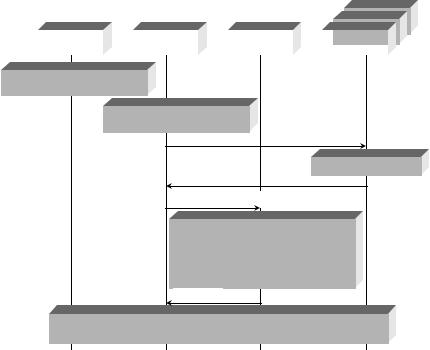
1. Identification of new condition in service area
2. Extraction of status of Network and of SLAs
3a. Offer request
3b. Offer request
3c. Offer request
4a. Optimization request
4b. Determination of new service provision pattern (QoS levels, traffic distribution to networks) Computation of
Tentative reconfigurations
4c. Reply
5. Solution acceptance phase. Reconfiguration of managed Network and managed components
Figure 1.5 MS-CRE operation scenario.
The architecture consists of three main logical entities:
monitoring, service-level information and resource brokerage (MSRB);
resource management strategies (RMS);
session managers (SMs).
The MSRB entity identifies the triggers (events) that should be handled by the MS-CRE and provides corresponding auxiliary (supporting) functionality. The RMS entity provides the necessary optimization functionality. The SM entity is in charge of interacting with the active subscribed users/terminals. The operation steps and cooperation of the RMS components are shown in Figures 1.5 and 1.6, respectively. In order to get an insight into the scope and range of possible reconfigurations, we review in Appendix A (please go to www.wiley.com/go/glisic) the network and protocol stack architectures [1–58] of the basic CRE components as indicated in Figure 1.1.
1.2 PROTOCOL BOOSTERS
As pointed out in Figure 1.2, an element of the reconfiguration in 4G networks is protocol booster. A protocol booster is a software or hardware module that transparently improves protocol performance. The booster can reside anywhere in the network or end systems, and may operate independently (one-element booster), or in cooperation with other protocol