

AutoCAD 2005 For Dummies (2004)
.pdf180 Part II: Let There Be Lines
Figure 8-1:
Leaning toward 3D.
Full 3D support is one of the main differentiators between full AutoCAD and AutoCAD LT. If you’re using AutoCAD LT, you can look at and plot 3D models created in AutoCAD, but you can’t do much 3D object creation or editing yourself. Also, viewing 3D models is less flexible in AutoCAD LT because it lacks AutoCAD’s 3DOrbit command.
Is 3D for Me?
The concept of 3D hardly seems to need introduction. We live in a threedimensional world, and most of the objects that you represent in your 2D AutoCAD drawings are three-dimensional.
Traditional 2D drawings provide clues to help the viewer’s mind construct a 3D model from the 2D image on paper. Multiple views from different viewpoints in 3D space give experienced designers, drafters, and builders the information they need to make 3D sense of 2D drawings. Design and drafting have succeeded pretty well by using 2D representations as the guide to creating 3D objects. But at some point, nothing can replace a true 3D model, such as in helping someone understand how a building will look when constructed or how two parts fit together.
What does using 3D in CAD mean? Fundamentally, it means creating models instead of views. Rather than create cross sections of an object or individual views of it from certain perspectives, you create a fully three-dimensional model of the object. This 3D depiction of each object includes all the necessary

Chapter 8: On a 3D Spree 181
information for AutoCAD to create a view from any point of view. With a properly constructed 3D model, AutoCAD can output commands to machines to create actual 3D objects, whether plastic prototypes carved from a tank of jelly by lasers or an actual bolt, valve, or piston created by computercontrolled machine tools.
AutoCAD, like most 3D CAD programs, enables you to create three different kinds of 3D models of objects:
Wireframes: A wireframe model is like a skeleton of a 3D object; it shows the edges of the object, not any of its surfaces. You create a set of 2D objects that represent an outline of each part of the object and then connect them three-dimensionally to make the wireframe. It’s like building a model from wire coat hangers. One of the biggest limitations of wireframe models is that you can’t shade them; there aren’t any surfaces “inside” the wire edges to catch the light — imagine shining a flashlight on a coat hanger.
Surfaces: A surface model represents the “skin” of an object but not the solid mass inside. AutoCAD uses objects called meshes to create surfaces. A mesh is a faceted surface that represents the edges and surfaces of a 3D object. You also can create a surface mesh by sweeping a 2D
object such as a polyline around an axis. Creating a surface model is like building a physical model out of thin sheets of balsa wood. A surface model is one step up from a wireframe model because you can apply material properties and shading to its surfaces.
Surface meshes are just the thing for some 3D modeling tasks, but they have limitations:
•Some 3D objects are awkward to build by pasting surfaces together.
•You can’t check mass properties or interferences of a surface model. (AutoCAD doesn’t recognize that there’s any solid mass inside the surfaces.)
Solids: A solid model is as close to true 3D as you can get without whipping out some Play-Doh and building a real-world model yourself. You build solid models by constructing basic 3D shapes and then combining them — adding, subtracting, or finding their intersections — and modifying them. It’s like using lots of fancy saws, drills, and glue to build a model made out of wooden blocks. You can render a solid model, as well as check mass properties and interferences.
In most practical applications of 3D, you select one type of representation — wireframe, surface, or solid — for all or most of the objects in the drawing, based on ease of construction and intended use of the model. However, AutoCAD doesn’t prevent you from mixing all three types of 3D objects in the same drawing.

182 Part II: Let There Be Lines
3D thumbs up
Using 3D takes time to master, creates additional work, and slows down your computer. Why bother using it? Here are four key reasons why anyone in his or her right mind would bother with 3D:
It’s the wave of the future. As CAD pursues greater realism and production efficiency, 3D is becoming important for more tasks in more professions. Drafters and designers who want to keep up with how CAD is likely to be used in the future should become familiar with 3D now.
Sometimes it’s nice. Drawing in 3D is useful for several tasks, including creating shaded renderings to help sell a design to a client, and fit-and-finish testing to find potential problems before a design is put into construction or manufacturing.
Sometimes it’s needed. Drawing in 3D is required for a small but growing number of tasks. Many mechanical designs are done in 3D or converted into 3D at some point in the design process. 3D perspective views make drawings easier to understand. And the shaded renderings used for both designing and selling are becoming a practical necessity in some fields.
Sometimes it’s faster. The fastest way to create a single view of something usually is to draw that view in 2D. If you need multiple views, it may be faster to create a 3D model and then slice and render it as needed for the views you want to create.
After you determine the type of 3D representation to use, you decide on the appropriate level of detail and construct the model, using the commands and techniques introduced in this chapter. Finally, you create the required 2D and/or rendered views for plotting or viewing on the screen.
You can do some experimentation with 3D on any computer system that can run AutoCAD. If you want to pursue serious work in 3D AutoCAD, pay attention to the following prerequisites:
Know AutoCAD well. You need to be pretty comfortable using AutoCAD for 2D work before doing much with 3D. You should be able to control object properties, use precision techniques, draw and edit 2D objects, and zoom and pan — in other words, all the stuff covered in Chapters 4 through 7 of this book. If you aren’t comfortable with these techniques in 2D drafting, you’re likely to find 3D modeling in AutoCAD a real struggle.
Get a fast computer. For beginning 3D work, any AutoCAD-adequate system will do the job. For serious work with 3D models, you need a fast computer, lots of memory, and lots of disk space.

Chapter 8: On a 3D Spree 183
Get and master additional software. In addition to AutoCAD, you may need other programs — either AutoCAD add-ons or separate packages — to do work that AutoCAD isn’t as good at. Specialized 3D modeling and rendering programs are among the tools of the trade of most people who do a lot of 3D work. Illustration packages can help you jazz up the appearance of your drawing.
Many of Autodesk’s newer software products — AutoCAD-based ones like Architectural Desktop and Mechanical Desktop and non-AutoCAD ones like Revit and Inventor (see Chapter 1 for more information) — use 3D modeling as their fundamental approach to CAD. If you intend to use 3D on real projects, you’ll probably use 3D-centric programs such as these, not plain AutoCAD. The information in this chapter will get you started on the right track, especially if you eventually use one of the AutoCAD-based applications.
Do a real project. Real work is the best motivation for discovering 3D. If you don’t have an actual work assignment, create a task. Something as “simple” as creating a 3D model of your chair will make the difference between really finding out something useful about 3D and just reading about it in the manuals.
3D thumbs down
Consider these issues before you decide how much to use 3D on a particular project:
2D input and editing: The mouse, keyboard, and drawing tablet are all 2D devices; the more complex the 3D object you’re trying to model, the more complicated it is to con-
struct the object with these devices. In addition, the AutoCAD 3D editing tools are fairly limited in scope — especially for solids. For most heavy-duty 3D work, you need a third-party application, a disci- pline-specific version of AutoCAD (such as Architectural Desktop), or a specialpurpose solid modeling program.
2D output: Most of the currently available output methods, notably paper and the
computer screen, are 2D. Presenting your 3D model in its full, three-dimensional glory requires extra work by you or the viewer.
Performance: Today’s personal computers are adequate for the task of storing fairly complex 2D models and displaying them onscreen and on plots; if the model is 3D, the difficulty increases geometrically, and performance seems to slow geometrically as well. You may need a faster computer and more memory to meet these demands. You may also find yourself taking longer coffee breaks as you wait for your computer to load or render complex 3D models.

184 Part II: Let There Be Lines
Getting Your 3D Bearings
The first challenge in 3D modeling is being able to see your three-dimensional model on a two-dimensional computer screen. The normal model space view on the Model tab in the drawing area shows a single, projected 2D view of your model — the top-down, “plan” view by default.
AutoCAD provides two model space capabilities that enable you to escape this visual flatland:
With viewports, you can carve the model space drawing area into smaller rectangular areas, each of which shows a different view of the model.
With viewpoints, you can change the point in 3D space from which you look at the model. By setting a different viewpoint in each viewport, you can look at several sides of your model at the same time. It’s like looking at one of Picasso’s cubist paintings, only more orderly.
If you want to experiment with viewports and viewpoints in an existing 3D drawing, try one of the AutoCAD2005 samples, such as \Program Files\ AutoCAD 2005\Sample\Welding Fixture Model.dwg. To remove shading and make the model faster to work with, choose View Shade 2D Wireframe.
Model space viewports left and right
Chapter 3 discusses viewports in paper space, which are useful for creating layouts for use in plots and presentations in both 2D and 3D. Model space viewports, cousins of paper viewports, are less powerful but simpler and are intended to help you construct 3D models.
Model space viewports divide the screen into separate rectangles with no gaps between them. Unlike with paper space viewports, you can’t move, stretch, or overlap them. You can’t plot multiple model space viewports; that’s what paper space is for. And, unlike in layouts, a layer that’s visible in one model space viewport always is visible in all of them.
You may hear or read references to tiled viewports, which is just another name for model space viewports. Tiled refers to the way in which model space viewports always fill the drawing area, with no gaps and no overlapping allowed.
Conversely, paper space viewports are sometimes called floating viewports because you can move them around, leave gaps between them, and overlap them.
Model space viewports enable you to see several views of your model at one time, each from a different viewpoint. For this reason, model space viewports are especially useful when you’re creating and editing objects in 3D. As you draw and edit, the different views help ensure that you’re picking points that are located correctly in 3D space.

Chapter 8: On a 3D Spree 185
To set up model space viewports, use the Viewports dialog box:
1.Choose View Viewports New Viewports.
The Viewports dialog box appears.
2.Choose one of the Standard Viewport arrangements and choose 3D in the Setup drop-down list.
3.Click OK.
Figure 8-2 shows the dialog box and the model space result of choosing the Four Right Standard Viewport arrangement and the 3D Setup. This arrangement, along with the Four Equal, and Four Left standard viewport arrangements, works well for creating viewports that show top, front, right, and isometric views of a 3D model.
Figure 8-2:
The Viewport dialog box makes setting up model space viewports and different viewpoints easy.
To return to a single viewport later, click in the one whose view you want to use, then open the Viewports dialog box and choose Single in the Standard Viewports list.
Seeing the world from new viewpoints
When you choose 3D in the Viewports dialog box’s Setup drop-down list, you direct AutoCAD to change the viewpoint in each viewport. The default viewpoints when you choose a four viewport arrangement are top, front, right, and isometric. These viewpoints work well for viewing and constructing simple models, but eventually, you’ll probably want to specify your own, custom viewpoint in a particular viewport.

186 Part II: Let There Be Lines
The easiest way to change viewpoints is to use the View 3D Views submenu (shown in Figure 8-3) to switch to one of the standard orthographic 3D views or an isometric view:
The six standard orthographic (straight-on) views are Top, Bottom, Left, Right, Front, Back.
The four standard isometric views are SW (left-front), SE (right-front), NE (right-back), and NW (left-back). An isometric view is one in which you see the object from above, but not too high above — as though you were hovering in a low-flying helicopter.
These ten views are called standard because they’re often used in manual drafting and rendering work. They work well for showing 3D models of common objects such as mechanical components and buildings. (You can also change to plan view, which is a top-down view of either the world coordinate system or a user coordinate system. I describe coordinate systems in “A Cartesian Orientation,” later in this chapter.)
You can specify nonstandard viewpoints by choosing View 3D Views Viewpoint Presets. In the Viewpoint Presets dialog box that appears, specify the following settings:
A viewing angle in the XY plane (imagine moving a camera on a dolly around an object, while keeping the camera at the same elevation)
An angle from the XY plane (imagine using a boom to swoop the camera up to a different height so that you’re looking at the object from increasingly steep angles)
Figure 8-3:
The 3D
Views submenu.

Chapter 8: On a 3D Spree 187
By default, AutoCAD shows 3D models in 2D wireframe mode, even if you’ve created surface or solid objects. If you want to better visualize which objects are in front of which other objects, especially in an isometric or other nonorthogonal view, you have a couple of options:
Choose View Shade and then choose Hidden or any of the Shaded options.
Render the model, as described later in this chapter.
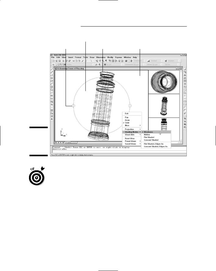
Dynamic viewpoints with 3DOrbit
Standard views and the Viewpoint Presets dialog box are fine for many 3D construction tasks, but if you really want to have fun with a model, 3DOrbit is your ticket to it.
AutoCAD LT doesn’t include the 3DOrbit command. In LT, you can use the DDVPOINT and DView commands to look at a model from different points of view.
The 3DOrbit command displays an arcball on the screen — a circle representing a sphere around your object. You click various places inside, outside, and on the arcball and then drag to change the 3D view. The idea is that you’re spinning the imaginary sphere containing your model. As you drag the cursor, AutoCAD updates the screen dynamically.
3DOrbit provides many other options through its right-click shortcut menu. You can change the shading mode and projection type, and you can turn on several visual aids that help you understand where you are in 3D space.
Additional shortcut menu options enable you to pan, zoom, and restore standard or named views.
The following steps show some of the things that you can do with 3DOrbit:
1.If you’ve divided model space into two or more viewports, click in the viewport in which you want to change the viewpoint.
2.Choose View 3D Orbit.
The 3DOrbit arcball appears, as shown in Figure 8-4.
3.Move the cursor inside the arcball.
The 3DOrbit full orbit cursor appears: two oval arrows circling a sphere.
4.Click and drag, keeping the cursor inside the arcball.
You can rotate the model in all directions. Imagine that the cursor is your finger pushing on a globe that rotates freely in all directions.
188 Part II: Let There Be Lines
Full orbit
Horizontal rotation |
Vertical rotation |
Roll |
Figure 8-4:
The 3DOrbit arcball and right-click menu.
Pay attention to the shaded UCS (user coordinate system) icon at the lower-left corner of the drawing area as you change the view. The UCS icon helps you visualize how each orbiting operation works. (The next section of this chapter tells more about UCSs.)
5.Release the mouse button and move the cursor outside the arcball.
The 3DOrbit roll cursor appears: a circular arrow circling a sphere.
6.Click and drag, keeping the cursor outside the arcball.
You can rotate the model around an axis at the center of the circle, coming out of the screen. Imagine that you’re turning the steering wheel on a car, with the steering column pointing into the screen.
7.Release the mouse button and move the cursor over one of the small circles at the quadrant points (that is, 12 o’clock, 3 o’clock, 6 o’clock, and 9 o’clock) of the arcball.
The 3DOrbit horizontal or vertical rotation cursor appears: an elliptical arrow circling a sphere.

Chapter 8: On a 3D Spree 189
8.Click and drag away from the small circle.
You can rotate the model around a horizontal axis (if you clicked the circle at 3 o’clock or 9 o’clock) or a vertical axis (if you clicked the circle at 12 o’clock or 6 o’clock) passing through the little circle. Imagine that you’re turning a piece of meat on a spit, with the spit located horizontally or vertically in the plane of the screen.
9.Release the mouse button and right-click in the drawing area.
The 3DOrbit shortcut menu, shown in Figure 8-4, appears.
10.Experiment with the additional options, such as Shading Modes and Projection.
Here’s the lowdown on some of these options:
•Gouraud Shaded usually looks more realistic than Flat Shaded.
•Hidden removes hidden lines but doesn’t shade.
•Wireframe is the default wireframe view, without hidden lines removed.
•Parallel projection is the default AutoCAD projection — lines that are parallel in the 3D object remain parallel in the projected view on the screen.
•Perspective projection makes objects look more realistic (for example, train tracks appear to converge in the distance), but lines that are parallel in the model don’t remain parallel in perspective projection.
If you manage to 3DOrbit out of control so that you no longer see your model, right-click to display the 3DOrbit shortcut menu and choose More Zoom Extents. The Zoom, Pan, and Preset Views options offer other ways of getting your model back in your sights.
11.When you’re finished orbiting, right-click in the drawing area and choose Exit.
Choose More Adjust Clipping Planes on the 3DOrbit right-click menu (or the 3DCLIP command outside of 3DOrbit) to slice away part of your model temporarily to view what’s inside the surfaces or solid boundaries. See “clipping, 3D objects” in the AutoCAD online help for more information.
You can control the camera point and target point that 3DOrbit uses (the point that you’re looking from and the point that you’re looking towards). Before you start the 3DOrbit command, type CAMERA at the command prompt and press Enter. Click or type the coordinates of the desired camera point target points.