

132 Ship Design for Efficiency and Economy
cargo ships. Problems may occur with vibrations as the propeller tip enters the semi-circle. To reduce these vibrations, the radius of the semi-nozzle can be increased such that the propeller tip approaches the nozzle gradually. Another problem may be the reduced static strength and stiffness of the semi-nozzle. This may be improved by stiffening the entrance of the semi-nozzle with foils which may in addition give a pre-rotation to the propeller inflow.
The costs for saddle nozzles are higher than for complete Kort nozzles. Furthermore, classification societies require proofs of strength and vibrational characteristics. These proofs may be more expensive than the nozzle itself. Thus despite successful model tests, so far only one coastal freighter has been equipped with a saddle nozzle.
Further development
Kort nozzle have developed with the following objectives:
1.Better astern operating performance.
2.Simpler shaping.
3.Simpler manufacturing.
4.Greater safety against inflow or intake of shingle.
5.Efficiency enhancement by the `Y-nozzle'.
4.6 Further devices to improve propulsion
Various devices to improve propulsionÐoften by obtaining a more favourable flow in the aftbodyÐhave been developed and installed since the early 1970s, motivated largely by the oil crisis (Alte and Baur, 1986; Blaurock, 1990;
¨
Ostergaard, 1996). Some of the systems date back much further, but the oil crisis gave the incentive to research them more systematically and to install them on a larger scale.
The Grim vane wheel
The Grim vane wheel consists of a relatively small propeller driven by the engine plant and a freely revolving propeller fitted on the downstream side, the inner part of which (behind the engine-driven propeller) acts as a turbine and the outer part as a propeller (Fig. 4.17) (Grim, 1966, 1980, 1982; Baur, 1985; Tanaka et al., 1990; Meyne and Nolte, 1991). This propulsion system has the following hydrodynamic advantages over normal single-propeller drive:
1.Substantial recovery of rotational energy.
2.Greater possible jet cross-section of vane wheel, since the low rpm rate and large number of blades enable smaller vertical clearances to be accepted.
3.Less resistance from rudder behind the vane wheel. This is reflected in the relative rotative efficiency.
4.Better stopping capability.
Moreover, the higher rpm rate associated with the smaller diameter of the engine-driven propeller improves the weight and cost of the propulsion unit. Grim proceeds from the assumption that the vane wheel is 20% larger in

Some unconventional propulsion arrangements 133
Figure 4.17 Vane wheel system (figure from Bremer Vulkan)
diameter than the mechanically driven propeller. The system appears suitable for a wide range of conventional cargo ships, but only few actual installations have been reported.
Asymmetric aftbodies
Since 1982, several ships have been built with asymmetric aftbodies as patented by Nonnecke¨ (1978,1987a,b) (Fig. 4.18). Model and full-scale tests indicate the following reasons for the power savings of 5±10%, especially for full hull forms (Collatz and Laudan, 1984; N. N., 1985; Nawrocki, 1989):
Bilge vortex generation is reduced on the side with V-section characteristics (portside for clockwise turning propeller). Local separation is reduced on
Figure 4.18 Hull sections of asymmetric aftbody
134 Ship Design for Efficiency and Economy
this side. This may lead to lower resistance for the asymmetric ship than the corresponding symmetrical ship in some cases.
The pre-rotation induced by the hull improves the propeller efficiency. Rudder (and a vane wheel) reduce rotation as well.
Grothues spoilers
Cross-flows are often, but not always, observed in model tests investigating the ship flow near the propeller. This phenomenon decreases with distance from the hull. In addition, bilge vortices appear (Fig. 4.19). The cross-flow usually has a thickness comparable to that of the boundary layer. Cross-flows appear predominantly in ships with stern bulb, high B=T, high CB and low speed. Cross-flows disturb the propeller inflow and reduce the propeller efficiency.
a = 0

 a
a
 2a
2a
3a
Figure 4.19 Cross-flow and bilge vortex
Grothues-Spork (1988) proposed spoilersÐfitted before the propeller on both sides of the stern postÐto straighten horizontally the boundary layer flow right before the propeller, thus creating direct thrust and improving the propeller efficiency. He used parts of a cylindrical surface such that they divert more strongly near the hull and less so further out. These fins are called Grothues spoilers (Fig. 4.20).
Power savings measured in model tests were:
Tankers and bulkers, fully loaded |
up to 6% |
Tankers and bulkers, in ballast |
up to 9% |
Some unconventional propulsion arrangements 135
Figure 4.20 Grothues spoilers in principle |
|
Ships of medium fullness with B=T < 2:8 |
up to 6% |
Fine vessels with small B=T |
up to 3% |
Special investigations on the spatial flow conditions in the propeller post region have to be made for the determination of shape, position and number of spoilers. The expense of manufacturing and fitting spoilers is generally low.
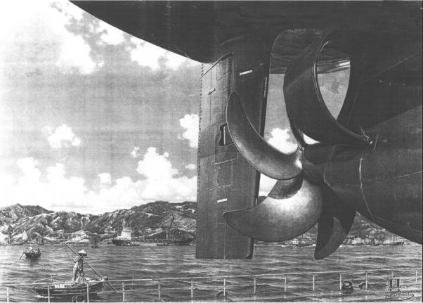
The wake equalizing duct
In the following, we will first treat wake equalizing ducts for single-screw ships. The wake equalizing duct (WED) is a ring-shaped flow vane with foil-type cross-section fitted to the hull in front of the upper propeller area (Fig. 4.21) (Schneekluth, 1985, 1989; Stein, 1983, 1996; N. N., 1986, 1992; Renner, 1992; Steirmann, 1986; Xian, 1989). The WED is by far the most frequently installed propulsion improving device (Meyne, 1991) (Table 4.1). In contrast to the Kort nozzle, which shrouds the propeller, these ducts are less than half as big in diameter and section length and are arranged in the wake. They are fitted to the hull in the form of two half-ring ducts in front of the propeller. Their upper ends may be integrated to the hull ahead of the stern frame or they may extend into the stern aperture, in which case the gap at the trailing edge aft of the stern frame is given a horizontal filling. WEDs consist usually of two centro-symmetric halves which are connected by straight foiltype parts to the hull. For an asymmetric stern fitting a half-ring duct on only one side can be more beneficial than the double-sided arrangement. The duct
Table 4.1 Installations of propulsion improving devices up to 1991
Wake equalizing duct |
>500 |
Asymmetric aftbody |
75 |
Vane wheel |
60 |
Grothues spoilers |
35 |
|
|
136
Figure 4.21 Wake equalizing duct (WED)

Some unconventional propulsion arrangements 137
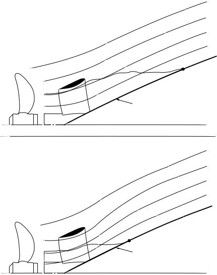
is most effective on the side with larger curvature of the waterlines. The basic principle underlying the application of this device is that the flow creates a circulation around the foil section of half-ring ducts which accelerates the flow in the area enclosed by them and retards it in their outer environment. Thus, such a nozzle channels the flow in the upper quadrants where it matters most. The inward-directed circulation guides the water into the duct, and ahead of it presses the flow on to the hull. The flow is then better attached to the hull and separation prior to the duct is reduced (Fig. 4.22).
Figure 4.22 Schematic diagram of flows
Top: flow along a waterline at a height of about 3/4 propeller diameter. In stern region separation occurs
Below: flow with duct, no separation
The WED is characterized by the following parameters:
Inner diameter (43±44% of propeller diameter).
Chord length (50±70% of inner diameter).
Profile section shape (special, not corresponding to any standards).
Angle of outline cone.
Angle of axis of half rings against the longitudinal and transverse planes of the ship, which have different settings for port and starboard sides.
Distance of axes from each otherÐtaken at the exit plane.
Distance of WED from propeller.
A normal longitudinal section across the duct explains the circulation effect relating to the speed distribution in the upper and lower halves of the propeller.

138 Ship Design for Efficiency and Economy
The inflow of the propeller is accelerated in the upper region where it is slow, corresponding to the fuller form of the ship, and in the lower region, where the speed of inflow is normally higher, it will be retarded. In practice the average and effective wake will hardly be changed (Fig. 4.23). In accelerating nozzles and ducts the open cross-section at the trailing edge is usually smaller than that at the leading edge. This often may not be so in WEDs. The flow in the WED region has divergent flowlines due to the ship hull form. The WED decreases this divergence by locally accelerating the flow in this region.
Figure 4.23 Circulation in vertical direction
Advantages of application
The main advantage lies in power savings resulting from various effects:
1.Improved propeller efficiency from more axial flow and more uniform velocity distribution over the disc area. The former effect dominates. Measurements on a containership model show that the angle of inward
inclination of flow in the plane behind the duct is reduced from as much as 20° to about 7° to the longitudinal axis of the ship. The asymmetrical arrangement of half ducts gives a rotational direction to the water entering the propeller, which is opposite to that which the propeller will impart. Thus the loss from rotation energy in the propeller wake is less.
2.Reduction of flow separation at the aftbody. This effect is strong and reduces resistance and the thrust deduction fraction.
3.Lift generation with a forward force component on the foil section, similar to but weaker than that in the Kort nozzle (Fig. 4.24).
4.The nozzle axes are oriented such that the propeller inflow is given a slight pre-rotation which counteracts the propeller rotation.
5.Improved steering qualities from more straightened flow to the rudder. In spade rudders the longer upper sections become more effective because of the higher flow velocity.

Some unconventional propulsion arrangements 139
Figure 4.24 Schematic diagram of lift with forward force component on duct
6.Improved course-keeping ability from increased lateral plan area aft.
7.No constructional changes and no modifications in propeller design are involved when the duct is fitted to an existing ship.
8.Possibility to integrate devices for ice protection to propeller. Even without special ice protection, ducts protect propellers. Up to 1997, almost 900 ducts had been installed, many in ships on ice-infested routes. No damage to ducts has been reported and ice-damage to propellers has been reduced.
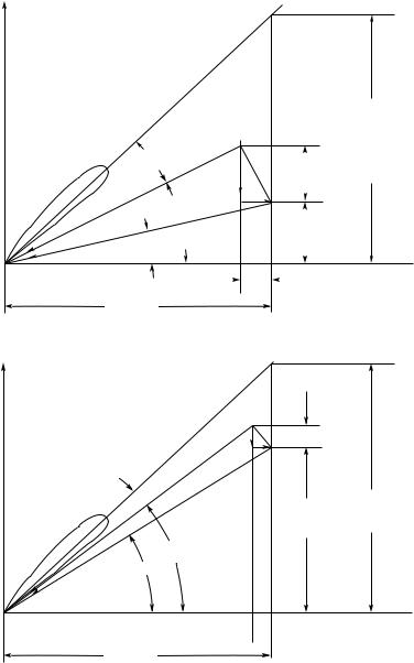
9.Reduction of propeller-excited vibrations from decreased propeller tip loading in upper quadrants to less than half the amplitudes. This allows reduction of propeller clearances in new designs. Reduced vibrations have in practice also decreased malfunctions of electronic equipment. The reduction in vibration amplitudes by the WED is easily explained by the velocity distribution. Larger inflow velocity means smaller angle
of attack between profile zero lift position and inflow direction (Fig. 4.25). The hydrodynamic forces and thus pressure impulses are roughly proportional to the angle of attack for small angles of attack. The WED also smooths the torque and thus reduces the tendency for torsional vibrations.
The power savings can be used to obtain higher speed. For a given speed, the power savings are converted to a lower rate of rotation.
The WED leads to a differently distributed inflow to the propeller, but not a higher average inflow velocity. In fact, the additional friction in the duct increases the wake fraction by some 0.01. This hardly changes the optimal propeller pitch. Thus, an often desired correction in propeller pitch cannot be achieved by a WED.
The positive effect of the WED in power saving is most evident in the speed range up to 23 knots. Generally the power gain increases with speed. The relationship of power gain to speed shows an analogous behaviour to that of effective wake and speed. The maximum advantage is obtained mostly at the full-load condition. At ballast draft the gain is smaller, mainly because of the stern trim associated with this draft condition. Model tests have determined a maximum energy saving of 14% at the same speed in several cases. In all cases (i.e. with or without duct) the results were converted by the standard procedure without any corrections for scale effects of the duct. The WED also offers the possibility of injecting air at the propeller for the purpose of reducing
140 Ship Design for Efficiency and Economy
advanceof |
|
|
lift |
direction |
||||||
|
Zero |
|
|
|
|
|
|
|
||
|
|
|
|
|
|
|
|
|
|
|
Direction |
££££££££¤¤¤¤¤¤¤¤¢¢¢¢¢¢¢¢RRRRRRRRSSSSSSSSQQQQQQQQ,,,,,,,,¥¥¥¥¥¥¥¥TTTTTTTT |
|
|
|
||||||
a |
|
W |
|
|
||||||
|
|
|||||||||
|
|
|
|
|
UA |
|||||
|
|
|
|
|
|
|||||
|
|
W1 |
|
|
||||||
|
|
|
|
|||||||
|
|
|
|
|
|
|||||
|
|
|
|
|
||||||
|
|
|
|
bi |
||||||
|
|
b |
|
|
|
UT |
|
|
|
|
|
|
|
|
|
|
|
|
|
||
|
|
|
|
|
|
|
|
|
|
|
|
|
|
|
|
|
|
|
|
|
|
|
|
|
|
|
|
|
||||
w.r
n.p
advanceof Direction,,,,,,,,,¤¤¤¤¤¤¤¤¤¥¥¥¥¥¥¥¥QQQQQQQQQRRRRRRRRR¢¢¢¢¢¢¢¢¢£££££££££SSSSSSSSSTTTTTTTT
Zero |
lift |
|
|
a |
|
b
direction W
bi
W1
UA
VA n.p
 UT
UT 
w.r
Figure 4.25 Velocities and angle of attack at propeller for low (top) and high (bottom) inflow velocity.
vA axial propeller inflow velocity !r radial velocity
uA additional velocity in axial direction uT additional velocity in radial direction w resultant inflow velocity
n propeller rpm P pitch
profile angle of attack
Some unconventional propulsion arrangements 141
the impulse impingement on the hull surface and of reducing cavitation. This option has never been used in practice, although it is simpler than injecting air via a canal system in the propeller blades.
Cavitation
Unlike ducted propellers, which are hardly used in ocean vessels due, in part, to problems of tip clearances and cavitation, the WED does not pose such problems. The more uniform flow into the propeller reduces the dangers of propeller cavitation. The duct itself is less exposed to this problem than the rudders because of the considerably lower flow velocity in the wake at its location, which is often less than half the ship speed. Another advantage here is that normally the WED is considered for moderate speed vessels with block coefficient above 0.6; fast ships, which tend to have cavitation problems, are less suited to its use.
Scope of application
To reduce possible propeller-excited vibrations and to improve hull efficiency, modern designs often incorporate stern bulbs, bigger propeller tip clearances and slender run of waterlines in the region of the upper quadrants. For concave waterlines in the region of the `critical waterline', i.e. half a propeller radius above the shaft height, the onset of flow separation may be too far ahead to be captured by the nozzle circulation. The nozzle cannot reverse separation once it has started. If in this case the nozzle is placed further ahead than usual, the interaction with the propeller deteriorates. The effect of not capturing the flow separation is mainly a problem for model tests, as flow separation is shifted further aft in full scale.
The bases for evaluation of economic gains are expected power savings from comparative model tests or from experience gained from other vessels fitted with the nozzle. Data required for a preliminary assessment consist of hull lines fullness and details of the propeller and its configuration.
In newbuilds, it is recommended that model tests be extended to include duct variants to determine the best arrangement and attainable gains, because these tests involve relatively low additional costs. For fitting to an existing ship, where a model has to be manufactured specially for this purpose, model testing can be rather costly.
Cost aspects
In newbuilds the costs of the duct can be lower than those costs saved by choice of a smaller engine, made possible by the power savings. Even when a suitable, next smaller engine is not available the shipowner still saves fuel, although the initial investment is then slightly higher. The investment for fabrication and fitting is invariably recovered in 6±20 months, depending on ship form and fuel price (Stiermann, 1986).
Integration in ship design
The interaction between the ship and the duct raises the question of whether there is further scope for improvement by adopting the aftbody design for duct integration. In ships with CB > 0:6, flow separation in the stern area
142 Ship Design for Efficiency and Economy
cannot be completely avoided. When duct integration is envisaged, it is better to locate these areas in the duct region, where it effectively reduces flow separation, i.e. the waterlines ahead of the duct should not be kept hollow but should have their greatest slope here. The increase in thrust deduction fraction from the greater waterline slope is more than compensated by the increased effectiveness of the duct. Similarly, the horizontal propeller blade clearance from the stern frame need not be kept wide to avoid undesirable effects from propeller action. Adequate smaller clearances, such that the duct does not completely extend into the aperture, also improve the duct effectiveness in respect of separation.
For new designs, the WED offers additional advantages.:
CThe ship hull can be kept simpler. The stern bulb can be built less pronounced and the counter can be placed lower. Concave waterlines at the height of the WED are not necessary, thus the hull is cheaper to produce and the resistance lower.
CSimpler propellers with fewer blades and less skew. The propellers can be more highly loaded at the tips. Thus the propellers are cheaper, yet more efficient.
Conversion of results from model tests
Unfortunately, even computations based on `Navier±Stokes' codes (see Section 2.11), have not yet been able to determine the power savings from WEDs. Accurate prediction of flow separation remains a problem. One still reverts to model testing or sea trials. If no model tests are envisaged prior to the installation of the duct, comparative test data to cover most cases can be used. Estimates based on comparable ships are generally in respect of design draught and speed. On the other hand it is commonly not possible to predict, without model tests, the amount by which the power savings will change with variation of speed, draught or trim. In a ship model with WED, significant scale effects occur, about which quantitatively little is known. These are in favour of the full-sized ship so that actual gains for the ship may be 2±3% higher than those predicted in model tests. This difference is not explained by the higher frictional resistance of the duct, as this would contribute only 0.3±0.5% to the total power prognosis. Sea trials and data obtained from long-term operation confirm power savings up to 8% on average over the whole range of service conditions in respect of draft and speed. For conversion of model test results to full scale, three factors act in favour of the full-sized ship, but are generally not taken into consideration for predictions given in the test reports.
1. Scale effects
The difference in frictional resistance coefficient for the duct in model and full scale is considerably higher than that allowed for by frictional deduction allowance for skin friction of ship and model. The difference in friction resistance coefficient cannot be ascertained easily because the flow velocity around the duct is not known unless measured. Another scale effect is due to lack of similarity in boundary layer thickness. Due to the relatively thinner boundary layer on the ship, the volume of water passing through the duct is bigger. As a third scale effect, the component of resistance from flow separation can be
Some unconventional propulsion arrangements 143
different in model and in ship. The separation effect is slightly more exaggerated in the model, implying that the possible reduction in separation can be greater here. The difference in flows at model and full scale is schematically displayed in Fig. 4.26. This separation effect is, unusually, in favour of the model.
,,,,,,,,,,,,,,,,,,,,Waterline on half
height of nozzle
,,,,,,,,,,
Waterline on half height of nozzle
Figure 4.26 Principle of different WED effect in full scale (top) and model scale (bottom); flowlines and areas of separation
2. Model similarity
In model tests the ducts are fitted to the ship model on shafts so that the setting of vertical and horizontal axis angles can be varied to determine the optimal

144 Ship Design for Efficiency and Economy
arrangement. The additional resistance of the shafts and the gaps at the connection of half-ring ducts to the ship model can increase the resistance, thus reducing the effectiveness of the ducts in the model.
3. Seastate influence
Comparisons between the ship with and without WED refer to smooth water performance. Model tests with a containership in smooth water and in regular waves show an additional power saving in seastates, amounting to about 3±4% for the model with duct, as against the model without it. The wavelength in these tests was from 0.5 to 1.5 ship length and the wave height was 3% of ship length.
Construction, fitting and mass
Construction and pre-fabrication of half-ring ducts is similar to that for the Kort nozzle. For practical reasons, the plate thickness in fabrication is much greater than strength considerations demand. Connection to the stern frame structure usually requires no additional internal stiffening of the stern frame. All WEDs so far have been built using welded construction. Shell plate thickness ranges from 7±14 mm for ducts of 1±3 m diameter. Fitting the WED to the ship in dock takes only a few days. The Thyssen Nordsee shipyards in Emden have developed a method to fit WEDs on floating, trimmed ships from a pontoon.
The weight of WED, mD [t] with a profile length of half the inner diameter Di [m] can be approximated by
mD Di2:3 0:48 0:1
Di
For a profile length of 0 :65Di we have:
mD Di2:5 0:47 C 0:1
The equations are for both half rings together and for Di > 1:2 m.
WED for twin-screw ships
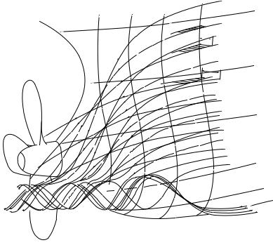
WEDs have also been installed successfully in twin-screw ships. Twin-screw ships usually feature more uniform wakes than single-screw ships. The wake affects the twin-screw propeller predominantly on the side near the hull and in the flow region behind the shaft brackets. The WED can equalize the wake also in this case, but should be concentric around the shaft, accelerating the flow in an arc from approximately 90 ° to 130° in the region of strong wake. In the region between WED and hull the flow will be slowed down. Power savings are thus derived from an increased propeller efficiency due to equalized wake and a reduced hull friction resistance behind the WED. Winglets at both tips of the WED segment may yield further power savings. The main effect of WED for single-screw ships, the reduction of separation, is not applicable for twinscrew ships. Yet installations in passenger ships showed speed improvements around half a knot. We cannot yet give a physical explanation for this effect. For new designs of twin-screw ships, WEDs can reduce the resistance of appendages, as shaft brackets can be kept shorter and more slender. Also, the water-immersed part of the shaft can be kept shorter or run at a lower angle
Some unconventional propulsion arrangements 145
towards the flow. If the propeller is not arranged closer to the hull, the propeller diameter may be increased. Figure 4.27 shows qualitatively the flow field for a twin-screw ship with and without a WED. WED for twin-screw ships are usually welded to the shaft brackets without further connecting elements.
,,,,,,,,,,,,,,,,,,QQQQQQQQQQQQQQQQQQ¢¢¢¢¢¢¢¢¢¢¢¢¢¢¢¢¢¢,,,,,,,,,,,,,QQQQQQQQQQQQQ¢¢¢¢¢¢¢¢¢¢¢¢¢,,,,,,,,,,,,,,QQQQQQQQQQQQQQ¢¢¢¢¢¢¢¢¢¢¢¢¢,,,,,,,,,,,,,,,,,,QQQQQQQQQQQQQQQQQQ¢¢¢¢¢¢¢¢¢¢¢¢¢¢¢¢¢¢¢ ,,,,,,,,,,,,,QQQQQQQQQQQQQ¢¢¢¢¢¢¢¢¢¢¢¢¢
Figure 4.27 Effect of WED on flow in twin-screw ships
Combination of devices
Devices to improve propulsion have also been successfully combined. However, savings given for individual systems will not add up completely for combinations of systems. The estimates of total efficiencies which can be obtained given below are just guidelines. Also, in practice such combinations are rarely found as the high complexity of the systems introduces additional initial and sometimes operating (maintenance and repair) costs. Designers therefore generally favourÐat least in times of relatively low fuel costsÐsimple solutions involving at most one system to improve propulsion, e.g. a WED.
Grim vane wheel and asymmetric aftbody
Combinations have been installed (e.g. Kringel and Nolte, 1985; Spruth et al., 1985). As both systems are based on the recovery of rotational energy, the

146 Ship Design for Efficiency and Economy
combination will give only 65±75% of the sum of the savings expected for each of the systems.
Grim vane wheel and Grothues spoilers
This combination is possible and has been tested on different ship types. The total efficiency improvement is 75±85% of the sum of the individual savings, as the resistance decrease given by the spoilers reduces the efficiency of the vane wheel.
Grim vane wheel and WED
The situation is similar to that for the combination vane wheel/spoiler systems, but the WED gives a slight additional rotation in the flow, reducing total savings to 70±80% of the sum of individual savings.
Grothues spoilers and asymmetric aftbody
Model tests for this combination were not encouraging as both systems aim to reduce bilge vortex formation.
Grothues spoilers and WED
Cross-flows, which motivated the development of spoilers, also decrease the WED efficiency. For ships featuring cross-flows, Grothues spoilers in front of the WED increase efficiency and decrease propeller vibrations. In these cases,
(a) |
(b) |
,,, |
|
|
,, |
|
|
(c)
Figure 4.28 Cross-flow near hull without (left) and with (right) Grothues spoilers in front of WED