


1
Main dimensions and main ratios
The main dimensions decide many of the ship's characteristics, e.g. stability, hold capacity, power requirements, and even economic efficiency. Therefore determining the main dimensions and ratios forms a particularly important phase in the overall design. The length L, width B, draught T, depth D, freeboard F, and block coefficient CB should be determined first.
The dimensions of a ship should be co-ordinated such that the ship satisfies the design conditions. However, the ship should not be larger than necessary. The characteristics desired by the shipping company can usually be achieved with various combinations of dimensions. This choice allows an economic optimum to be obtained whilst meeting company requirements.
An iterative procedure is needed when determining the main dimensions and ratios. The following sequence is appropriate for cargo ships:
1.Estimate the weight of the loaded ship. The first approximation to the weight for cargo ships uses a typical deadweight:displacement ratio for the ship type and size.
2.Choose the length between perpendiculars using the criteria in Section 1.1.
3.Establish the block coefficient.
4.Determine the width, draught, and depth collectively.
The criteria for selecting the main dimensions are dealt with extensively in subsequent chapters. At this stage, only the principal factors influencing these dimensions will be given.
The length is determined as a function of displacement, speed and, if necessary, of number of days at sea per annum and other factors affecting economic efficiency.
The block coefficient is determined as a function of the Froude number and those factors influencing the length.
Width, draught and depth should be related such that the following requirements are satisfied:
1.Spatial requirements.
2.Stability.
3.Statutory freeboard.
4.Reserve buoyancy, if stipulated.
1

2 Ship Design for Efficiency and Economy
The main dimensions are often restricted by the size of locks, canals, slipways and bridges. The most common restriction is water depth, which always affects inland vessels and large ocean-going ships. Table 1.1 gives maximum dimensions for ships passing through certain canals.
Table 1.1 Main dimensions for ships in certain canals
Canal |
Lmax (m) |
Bmax (m) |
Tmax (m) |
Panama Canal |
289.5 |
32.30 |
12.04 |
Kiel Canal |
315 |
40 |
9.5 |
St Lawrence Seaway |
222 |
23 |
7.6 |
Suez Canal |
|
|
18.29 |
|
|
|
|
1.1 The ship's length
The desired technical characteristics can be achieved with ships of greatly differing lengths. Optimization procedures as presented in Chapter 3 may assist in determining the length (and consequently all other dimensions) according to some prescribed criterion, e.g. lowest production costs, highest yield, etc. For the moment, it suffices to say that increasing the length of a conventional ship (while retaining volume and fullness) increases the hull steel weight and decreases the required power. A number of other characteristics will also be changed.
Usually, the length is determined from similar ships or from formulae and diagrams (derived from a database of similar ships). The resulting length then provides the basis for finding the other main dimensions. Such a conventional ship form may be used as a starting point for a formal optimization procedure. Before determining the length through a detailed specific economic calculation, the following available methods should be considered:
1.Formulae derived from economic efficiency calculations (Schneekluth's formula).
2.Formulae and diagrams based on the statistics of built ships.
3.Control procedures which limit, rather than determine, the length.
1. Schneekluth's formula
Based on the statistics of optimization results according to economic criteria, the `length involving the lowest production costs' can be roughly approximated by:
L |
|
10:3 |
|
V0:3 |
|
3:2 |
|
CB C 0:5 |
|
|
pp D |
|
|
.0:145=Fn/ C 0:5 |
|||||||
|
|
|
|
|||||||
where:
Lpp D length between perpendiculars [m] 1 D displacement [t]
V D speed (kn) p
Fn D V= g L = Froude number
The formula is applicable for ships with 1 1000 t and 0:16 Fn 0:32.
Main dimensions and main ratios 3
The adopted dependence of the optimum ship's length on CB has often been neglected in the literature, but is increasingly important for ships with small CB. Lpp can be increased if one of the following conditions applies:
1.Draught and/or width are limited.
2.No bulbous bow.
3.Large ratio of underdeck volume to displacement.
Statistics from ships built in recent years show a tendency towards lower Lpp than given by the formula above. Ships which are optimized for yield are around 10% longer than those optimized for lowest production costs.
2. Formulae and diagrams based on statistics of built ships
1. Ship's length recommended by Ayre:
L |
D 3:33 C 1:67 |
V |
||
|
p |
|
||
1=3 |
||||
L |
||||
r |
|
|
||
2.Ship's length recommended by Posdunine, corrected using statistics of the Wageningen towing tank:
L D C |
V |
|
2 r1=3 |
V |
2 |
||
|
C |
|
|
C D 7:25 for freighters with trial speed of V D 15:5±18:5 kn. In both formulae, L is in m, V in kn and r in m3.
3. Volker's¨ (1974) statistics
L V r1=3 D 3:5 C 4:5 q
gr1=3
V in m/s. This formula applies to dry cargo ships and containerships. For reefers, the value L=r1=3 is lower by 0.5; for coasters and trawlers by 1.5.
The coefficients in these formulae may be adjusted for modern reference ships. This is customary design practice. However, it is difficult to know from these formulae, which are based on statistical data, whether the lengths determined for earlier ships were really optimum or merely appropriate or whether previous optimum lengths are still optimum as technology and economy may have changed.
Table 1.2 Length Lpp [m] according to Ayre, Posdunine and Schneekluth
|
|
|
|
|
Schneekluth |
|
|
r [t] |
V [kn] |
Ayre |
Posdunine |
CB D 0:145=Fn |
CB D 1:06 1:68Fn |
1 000 |
10 |
55 |
50 |
51 |
53 |
|
1 000 |
13 |
61 |
54 |
55 |
59 |
|
10 000 |
16 |
124 |
123 |
117 |
123 |
|
10 000 |
21 |
136 |
130 |
127 |
136 |
|
100 000 |
17 |
239 |
269 |
236 |
250 |
|
|
|
|
|
|
|
|

4 Ship Design for Efficiency and Economy
In all the formulae, the length between perpendiculars is used unless stated otherwise. Moreover, all the formulae are applicable primarily to ships without bulbous bows. A bulbous bow can be considered, to a first approximation, by taking L as Lpp C 75% of the length of the bulb beyond the forward perpendicular, Table 1.2.
The factor 7.25 was used for the Posdunine formula. No draught limitations, which invariably occur for 1 100 000 t, were taken into account in Schneekluth's formulae.
3. Usual checking methods
The following methods of checking the length are widely used:
1.Checking the length using external factors: the length is often restricted by the slipway, building docks, locks or harbours.
2.Checking the interference of bow and stern wave systems according to the Froude number. Unfavourable Froude numbers with mutual reinforcement
between bow and stern wave systems should be avoided. Favourable Froude numbers feature odd numbers for the ratio of wave-making length L0 to half-
wave length =2 showing a hollow in the curves of the wave resistance coefficients, Table 1.3. The wave-making length L0 is roughly the length of the waterline, increased slightly by the boundary layer effect.
Table 1.3 Summary of interference ratios
Fn |
RF=RT (%) |
|
L0:. =2/ |
Normal for ship's type |
0.19 |
70 |
Hollow |
9 |
Medium-sized tankers |
0.23 |
60 |
Hump |
6 |
|
0.25 |
60 |
Hollow |
5 |
Dry cargo ship |
0.29±0.31 |
50 |
Hump |
4 |
Fishing vessel |
0.33±0.36 |
40 |
Hollow |
3 |
Reefer |
0.40 |
|
|
2 |
|
0.50 |
30±35 |
Hump |
1.28 |
Destroyer |
0.563 |
|
|
1 |
|
|
|
|
|
|
Wave breaking complicates this simplified consideration. At Froude numbers around 0.25 usually considerable wave breaking starts, making this Froude number in reality often unfavourable despite theoretically favourable interference. The regions 0:25 < Fn < 0:27 and 0:37 < Fn < 0:5 should be avoided, Jensen (1994).
It is difficult to alter an unfavourable Froude number to a favourable one, but the following methods can be applied to reduce the negative interference effects:
1.Altering the length
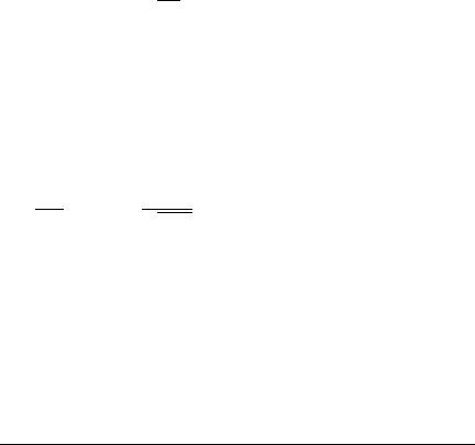
To move from an unfavourable to a favourable range, the ship's length would have to be varied by about half a wavelength. Normally a distortion of this kind is neither compatible with the required characteristics nor economically justifiable. The required engine output decreases when the ship is lengthened, for constant displacement and speed, Fig. 1.1. The Froude number merely gives this curve gentle humps and hollows.
2.Altering the hull form
One way of minimizing, though not totally avoiding, unfavourable interferences is to alter the lines of the hull form design while maintaining
Main dimensions and main ratios 5
Figure 1.1 Variation of power requirements with length for constant values of displacement and speed
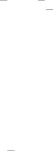
the specified main dimensions. With slow ships, wave reinforcement can be decreased if a prominent forward shoulder is designed one wavelength from the stem, Fig. 1.2. The shoulder can be placed at the end of the bow wave, if CB is sufficiently small. Computer simulations can help in this procedure, see Section 2.11.
Figure 1.2 Interference of waves from bow and forward shoulder. The primary wave system, in particular the build-up at the bow, has been omitted here to simplify the presentation
3.Altering the speed
The speed is determined largely in accordance with the ideas and wishes of the shipowner, and is thus outside the control of the designer. The optimum speed, in economic terms, can be related both to favourable and to unfavourable Froude numbers. The question of economic speed is not only associated with hydrodynamic considerations. Chapter 3 discusses the issue of optimization in more detail.
1.2 Ship's width and stability
When determining the main dimensions and coefficients, it is appropriate to keep to a sequence. After the length, the block coefficient CB and the ship's width in relation to the draught should be determined. CB will be discussed later in conjunction with the main ratios. The equation:
r D L B T CB
6 Ship Design for Efficiency and Economy
establishes the value of the product B T. The next step is to calculate the width as a factor in this product. When varying B at the design stage, T and D are generally varied in inverse ratio to B. Increasing B in a proposed design, while keeping the midship section area (taken up to the deck) constant, will have the following effects:
1.Increased resistance and higher power requirements: RT D f.B=T/.
2.Small draught restricts the maximum propeller dimensions. This usually means lower propulsive efficiency. This does not apply if, for other reasons, the maximum propeller diameter would not be used in any case. For example, the propulsion unit may call for a high propeller speed which makes a smaller diameter essential.
3.Increased scantlings in the bottom and deck result in greater steel weight. The hull steel weight is a function of the L=D ratio.
Items (1) to (3) cause higher production costs.
4.Greater initial stability:
KM becomes greater, KG smaller.
5.The righting arm curve of the widened ship has steeper initial slope (resulting from the greater GM), but may have decreased range.
6.Smaller draughtÐconvenient when draught restrictions exist.
B may be restricted by building dock width or canal clearance (e.g. Panama width).
Fixing the ship's width
Where the width can be chosen arbitrarily, the width will be made just as large as the stability demands. For slender cargo ships, e.g. containerships, the resulting B=T ratios usually exceed 2.4. The L=B ratio is less significant for the stability than the B=T ratio. Navy vessels feature typical L=B 9 and rather high centre of gravities and still exhibit good stability. For ships with restricted dimensions (particularly draught), the width required for stability is often exceeded. When choosing the width to comply with the required stability, stability conducive to good seakeeping and stability required with special loading conditions should be distinguished:
1.Good seakeeping behaviour:
(a)Small roll amplitudes.
(b)Small roll accelerations.
2.Special loading conditions, e.g.:
(a)Damaged ship.
(b)People on one side of the ship (inland passenger ships).
(c)Lateral tow-rope pull (tugs).
(d)Icing (important on fishing vessels).
(e)Heavy derrick (swung outboard with cargo).
(f)Grain cargoes.
(g)Cargoes which may liquefy.
(h)Deck cargoes.
Formerly a very low stability was justified by arguing that a small metacentric height GM means that the inclining moment in waves is also small. The
Main dimensions and main ratios 7
apparent contradiction can be explained by remembering that previously the sea was considered to act laterally on the ship. In this situation, a ship with low GM will experience less motion. The danger of capsizing is also slight. Today, we know a more critical condition occurs in stern seas, especially when ship and wave speed are nearly the same. Then the transverse moment of inertia of the waterplane can be considerably reduced when the wave crest is amidships and the ship may capsize, even in the absence of previous violent motion. For this critical case of stern seas, Wendel's method is well suited (see Appendix A.1, `German Navy Stability Review'). In this context, Wendel's experiments on a German lake in the late 1950s are interesting: Wendel tested ship models with adjustable GM in natural waves. For low GM and beam seas, the models rolled strongly, but seldomly capsized. For low GM and stern seas, the models exhibited only small motions, but capsized suddenly and unexpectedly for the observer.
Recommendations on metacentric height
Ideally, the stability should be assessed using the complete righting arm curve, but since it is impossible to calculate righting arm curves without the outline design, more easily determined GM values are given as a function of the ship type, Table 1.4. If a vessel has a GM value corresponding well to its type, it can normally be assumed (in the early design stages) that the righting arm curve will meet the requirements.
Table 1.4 Standard GM Ðfor `outward journey', fully loaded
|
|
|
|
Ship type |
|
GM [m] |
|
|
|
||
Ocean-going passenger ship |
1.5±2.2 |
||
Inland passenger ship |
0.5±1.5 |
||
Tug |
1.0 |
|
|
Cargo ship |
0.8±1.0 |
||
Containership |
0.3±0.6 |
||
|
|
|
|
Tankers and bulkers usually have higher stability than required due to other design considerations. Because the stability usually diminishes during design and construction, a safety margin of 1GM D 0:1±0:2 m is recommended, more for passenger ships.
When specifying GM, besides stating the journey stage (beginning and end) and the load condition, it is important to state whether the load condition specifications refer to grain or bale cargo. With a grain cargo, the cargo centre of gravity lies half a deck beam higher. On a normal cargo ship carrying ore, the centre of gravity is lowered by about a quarter of the hold depth. The precise value depends on the type of ore and the method of stowage.
For homogeneous cargoes, the shipowner frequently insists that stability should be such that at the end of operation no water ballast is needed. Since changeable tanks are today prohibited throughout the world, there is less tank space available for water ballast.
The GM value only gives an indication of stability characteristics as compared with other ships. A better criterion than the initial GM is the
8 Ship Design for Efficiency and Economy
complete righting arm curve. Better still is a comparison of the righting and heeling moments. Further recommendations and regulations on stability are listed in Appendix A.1.
Ways of influencing stability
There are ways to achieve a desired level of stability, besides changing B:
(A) Intact stability
Increasing the waterplane area coefficient CWP
The increase in stability when CWP is increased arises because:
1.The transverse moment of inertia of the waterplane increases with a tendency towards V-form.
2.The centre of buoyancy moves upwards.
Increasing CWP is normally inadvisable, since this increases resistance more than increasing width. The CWP used in the preliminary design should be relatively small to ensure sufficient stability, so that adhering to a specific predefined CWP in the lines plan is not necessary. Using a relatively small CWP in the preliminary design not only creates the preconditions for good lines, but also leads to fewer difficulties in the final design of the lines.
Lowering the centre of gravity
1.The design ensures that heavy components are positioned as low as possible, so that no further advantages can be expected to result from this measure.
2.Using light metal for the superstructure can only be recommended for fast vessels, where it provides the cheapest overall solution. Light metal superstructures on cargo ships are only economically justifiable in special circumstances.
3.Installing fixed ballast is an embarrassing way of making modifications to a finished ship and, except in special cases, never deliberately planned.
4.Seawater ballast is considered acceptable if taken on to compensate for spent fuel and to improve stability during operation. No seawater ballast should be needed on the outward journey. The exception are ships with deck cargo: sometimes, in particular on containerships, seawater ballast is allowed on the outward journey. To prevent pollution, seawater ballast can only be stored in specially provided tanks. Tanks that can carry either water or oil are no longer allowed. Compared to older designs, modern ships must therefore provide more space or have better stability.
Increasing the area below the righting arm curve by increasing reserve buoyancy
1.Greater depths and fewer deckhouses usually make the vessel even lighter and cheaper. Generally speaking, however, living quarters in deckhouses are preferred to living quarters in the hull, since standardized furniture and facilities can better be accommodated in deckhouses.
2.Inclusion of superstructure and hatchways in the stability calculation. Even today, some ships, particularly those under 100 m in length, have a poop,

Main dimensions and main ratios 9
improving both seakeeping and stability in the inclined position, although the main reason for using a poop or a quarterdeck instead of a deckhouse is an improved freeboard. Full-width superstructures enter the water at a smaller angle of inclination than deckhouses, and have a greater effect on stability. The relevant regulations stipulate that deckhouses should not be regarded as buoyancy units. The calculations can, however, be carried out either with or (to simplify matters) without full-width superstructure. Superstructure and steel-covered watertight hatches are always included in the stability calculation when a sufficient level of stability cannot be proved without them.
3.Increasing the outward flare of framing above the constructed waterlineÐa flare angle of up to 40 ° at the bow is acceptable for ocean-going vessels.
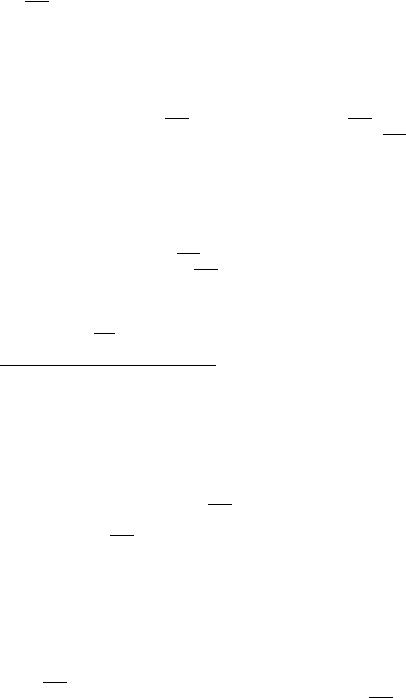
4.Closer subdivision of the double bottom to avoid the stability-decreasing effect of the free surfaces (Fig. 1.3)
5.For ships affected by regulations concerning ice accretion, the `upper deck purge' is particularly effective. The masts, for example, should be, as far as possible, without supports or stays.
Figure 1.3 Double bottom with four-fold transverse subdivision
(B) Damaged stability
The following measures can be taken to ensure damaged stability:
1.Measures mentioned in (A) improving intact stability will also improve damaged stability.
2.Effective subdivision using transverse and longitudinal bulkheads.
3.Avoid unsymmetrical flooding as far as possible (Fig. 1.4), e.g. by crossflooding devices.
4.The bulkhead deck should be located high enough to prevent it submerging before the permissible angle (7°±15°).
Approximate formulae for initial stability
To satisfy the variety of demands made on the stability, it is important to find at the outset a basis that enables a continuing assessment of the stability conditions at every phase of the design. In addition, approximate formulae for the initial stability are given extensive consideration.
The value KM can be expressed as a function of B=T, the value KG as a function of B=D.
A preliminary calculation of lever arm curves usually has to be omitted in the first design stage, since the conventional calculation is particularly time
10 Ship Design for Efficiency and Economy
Figure 1.4 Asymmetrical flooding with symmetrical construction
consuming, and also because a fairly precise lines plan would have to be prepared for computer calculation of the cross-curves of stability. Firstly, therefore, a nominal value, dependent on the ship type and freeboard, is specified for GM. This value is expected to give an acceptable lever arm curve.
The metacentric height is usually expressed as sum of three terms: GM D KB C BM KG. KG will be discussed in Chapter 5, in connection with the weight calculation. Approximate formulae for KB and BM can be expressed as functions of the main dimensions, since a more precise definition of the ship's form has yet to be made at this early stage.
The main dimensions CB, L, B, T and D are determined first. The midship section area CM, although not fixed in the early design stages, can vary only slightly for normal ship forms and is taken as a function of CB. Its influence on the stability is only marginal. The waterplane area coefficient CWP is rarely determined before the lines design is complete and can vary greatly in magnitude depending on form (U or V sections). Its influence on the stability is considerable. Approximate values are given in Section 1.6.
Height of the centre of buoyancy above the keel
Literature on the subject has produced a series of good formulae for the value KB:
Normand |
KB |
T |
5 |
1 CB=CWP |
||
Normand |
|
D T.06:9 |
30:36 |
C |
/ |
|
KB |
||||||
Schneekluth |
|
D |
|
|
M |
|
KB |
D T.0:9 0:3 CM 0:1 CB/ |
|||||
Wobig |
|
D T.0:78 0:285CB=CWP/ |
||||
KB |
||||||
The accuracy of these formulae is usually better than 1% T. For the first formula, CWP may be estimated from approximate formulae.
Height of metacentre above the centre of buoyancy
The approximate formulae start from the equation BM D IT=r, where the transverse moment of inertia of the waterplane IT is expressed as the moment of inertia of the circumscribing rectangle L B3=12 multiplied by a reduction

Main dimensions and main ratios 11
factor. This reduction factor is expressed as a function of CWP:
|
|
IT |
|
f.CWP/ L B3 |
|
f.CWP/ |
|
B2 |
|
BM |
|||||||||
D r |
D 12 L B T CB D |
12 |
T CB |
||||||
|
|||||||||
Approximate formulae for the reduction factor are:
Murray (trapezoidal waterplanes) |
f.CWP/ D 1:5 CWP 0:5 |
|
Normand |
f.CWP/ D 0:096 C 0:89 CWP2 |
|
Bauer |
f.CWP/ D 0:0372.2 CWP C 1/3 |
|
N.N. |
f.CWP/ D 1:04 |
CWP2 |
Dudszus and Danckwardt |
f.CWP/ D 0:13 |
CWP C 0:87 |
|
CWP2 0:005 |
|
These formulae are extremely precise and generally adequate for design purposes. If unknown, CWP can be estimated using approximate formulae as a function of CB. In this way, the height of the metacentre above the
centre of buoyancy BM is expressed indirectly as a function of CB. This is always advisable when no shipyard data exist to enable preliminary calculation of CWP. All formulae for f.CWP/ apply to vessels without immersed transom sterns.
Height of the metacentre above keel
|
|
|
|
|
|
|
|
|
|
|
|
|
|
|
|
|
2 |
|
|
|
|
|
3 |
|
|
|
13:61 45:4 |
CB |
|
C 52:17 |
|
CB |
19:88 |
|
CB |
! |
|||||||||||
|
KM D B |
|
|||||||||||||||||||||
|
CWP |
CWP |
CWP |
||||||||||||||||||||
This formula is applicable for 0:73 < CB=CWP < 0:95 |
|
|
|
|
|||||||||||||||||||
|
|
|
|
0:08 B |
0:9 |
|
0:3 |
CM |
|
0:1 |
|
CB |
! |
|
|
|
|||||||
|
KM D B |
|
|
|
|
||||||||||||||||||
|
|
|
CM T C C |
|
|
|
B=T |
|
|
|
|
|
|||||||||||
|
|
|
|
p |
|
|
|
|
|
|
|
|
|
|
|
|
|
|
|
|
|
|
|
|
|
|
|
|
|
|
|
|
|
|
|
|
|
|
|
|
|
|
|
|
|
|
|
This formula (Schneekluth) can be used without knowledge of CWP assuming that CWP is `normal' corresponding to:
CWP;N D .1 C 2CB=p |
|
/=3 |
|
|
|
||||
CM |
|
|
|
||||||
Then C |
D |
1. If C |
WP is better |
known, the formula can be made more precise |
|||||
|
|
|
2 |
where CWP;A |
is the actual and CWP;N the |
||||
by setting C D .CWP;A=CWP;N/ |
|
||||||||
normal waterplane area coefficient.
For ships with pronounced V sections, such as trawlers or coasters, C D 1:1±1.2.
For a barge with a parallel-epiped form, this formula produces for B=T D 2 an error 1KM D 1:6%, and
for B=T D 10 an error 1KM D C4:16%.

12 Ship Design for Efficiency and Economy
The formula assumes a `conventional ship form' without pronounced immersed transom stern and relates to full-load draught. For partial loading, the resultant values may be too small by several per cent.
The above formula by Schneekluth is derived by combining approximate formulae for KB and BM:
|
|
|
|
|
|
|
|
|
|
T |
|
.0:9 |
|
0:3 |
C |
|
0:1 |
|
C / |
|
.3CWP 1/B2 |
|
|
|||||||||
|
KM |
|
KB |
|
BM |
|
|
|
|
M |
|
|||||||||||||||||||||
|
|
|
|
|
|
|
|
|
|
|||||||||||||||||||||||
|
|
D |
|
C |
|
|
|
D |
|
|
|
|
|
|
|
|
B |
C |
24 C T |
|
|
|
||||||||||
|
|
|
|
|
|
|
|
|
|
|
|
|
|
|
|
|
|
|
|
|
|
|||||||||||
|
|
|
|
|
|
|
|
|
|
| |
|
|
|
|
|
{z |
|
|
|
} |
|
|
|
|
|
|
|
|
||||
|
|
|
|
|
|
|
|
1 |
|
|
|
|
|
p |
|
|
|
|
|
|
|
|
| |
|
{z |
} |
|
|||||
|
|
|
|
|
|
|
|
|
|
|
|
|
|
|
Schneekluth |
|
|
|
|
|
|
B |
|
|
|
|||||||
Substituting |
CWP D |
3 .1 |
C 2CB= |
|
|
/ in Murray's |
formula |
yields |
|
|
D |
|||||||||||||||||||||
|
CM |
|
BM |
|||||||||||||||||||||||||||||
|
|
|
|
p |
|
|
|
|
|
|
|
|
|
|
|
|
|
|
|
|
|
|
|
|
|
|
|
|
|
|
||
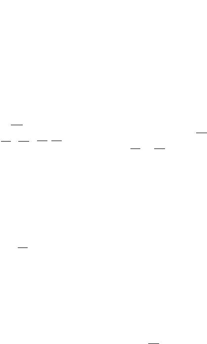
0:0834B.B=T/= CM. Since Murray's |
formula |
|
can |
be |
applied exactly for |
|||||||||||||||||||||||||||
trapezoidal waterplanes, (Fig. 1.5), the value must be reduced for normal waterplanes. The constant then becomes 0.08.
Figure 1.5 Comparison of ship's waterplane with a trapezium of the same area
The precision attainable using this formula is generally sufficient to determine the main dimensions. In the subsequent lines design, it is essential that BM D IT=r is checked as early as possible. The displacement r is known. The transverse moment of inertia of the waterplane can be integrated numerically, e.g. using Simpson's formula.
Approximate formulae for inclined stability
At the design stage, it is often necessary to know the stability of inclined ships. The relationship
|
|
|
tan2 |
|
|
|
1 |
|
|
|
|
|
|
h D BM |
C GM!sin |
BM 3 C GM |
|||||||||||
2 |
2 |
|
|||||||||||
(`wallside formula') is correct for:
1.Wall-sided ships.
2.No deck immersion or bilge emergence.
The error due to inclined frame lines is usually smaller than the inaccuracy of the numerical integration up to 10°, provided that the deck does not immerse nor the bilge emerge. There are methods for approximating greater inclinations, but compared to the formulae for initial stability, these are more time consuming and inaccurate.