

Lm016L
.pdfApplication Notes for Character Mode LCDs |
Page 1 of 24 |
Novel Engineering Worldwide Solutions
Dot Matrix LCD Character Modules
Application Notes
Table of Contents
1.SELECTING AN LCD MODULE
A.Introduction
B.Fluid Types
C.Viewing Modes and Colors
D.Backlighting
1.EL Backlit
2.LED Backlit
2.HARDWARE DESIGN
A.Power Supply Requirements
B.Temperature Compensation
C.Interface
D.Unique Timing Aspects of A/N LCDs
E.Mounting Suggestions
3.SOFTWARE REQUIREMENTS
A.Introduction
B.Initialization
C.4-bit Operation
D.Display Addressing
E.Specially Coded Displays
F.Instruction Table
G.Instruction Description
H.Use of CG RAM
4.APPENDIX
A.Designers Checklist
B.Precautions for Handling and Operating LCD Modules
C.Troubleshooting Guide
D.Timing Diagrams
E.Font Chart
F.Processor Specific Interface Suggestions
G.Polarizer Type Summary
I.SELECTING an LCD MODULE
A. INTRODUCTION
Selecting an LCD module involves 2 basic design decisions. 1) What size and format is required to display the desired information. 2) What optical characteristics will look best in the package and attract the user to the product. Densitron produces dot-matrix LCDs in two formats: fully functional, Alphanumeric Modules; and fully-populated Graphic modules. This set of application notes is for use with the alphanumeric (A/N) or character type modules. Refer to separate specifications and application notes for operating graphic modules.
04/09/98
Application Notes for Character Mode LCDs |
Page 2 of 24 |
Alpha-numeric modules display characters, numerals, symbols and some limited graphics. Interface is achieved via a bi-directional, parallel ASCII data bus. Necessary features such as Character Generation, Display RAM Addressing, Cursor Scrolling, Blanking, and Handshake are all included. User programmable fonts are supported. In summary, these modules are the simplest and most economic means to communicate meaningfully between any micro-system and the outside world. Their inclusion adds to any product's appeal.
Alpha-numeric modules range from 8 to 80 characters per line. One, two or four character lines may be chosen. Character height spans 0.130" (3.31 mm) to 0.500" (12.71 mm). Most formats are available in a variety of packages to meet various mounting requirements. Multi-line models offer the best value when analyzed by a "cost per character" basis. Displays are readable both day and night by selecting a backlight option. Extended temperature modules are available which operate between -20 and +70C.
For requirements of more than 4 lines or 40 characters across, select a graphic formatted module. Graphic modules are also used when different sized characters are needed, and when special fonts such as Chinese or Arabic are required.
Selecting the exact version of an LCD once the format is decided is largely a subjective judgement. Color, fluid type, and backlighting determine the overall look of the display and often the appearance of the end product. Operating conditions such as temperature, lighting conditions, and available power are also factors in determining the type of display to use.
The following sections explains the optical characteristic options available in A/N modules,
B. FLUID TYPES
The fluid type determines the contrast ratio, viewing angle, and temperature range of an LCD. Densitron uses 3 basic classes of fluid, TN (Standard type), NTN (high contrast type), and STN (premium high contrast type). Many TN and NTN models are available in extended temperature range. Contact Densitron for current availability.
TN Fluid
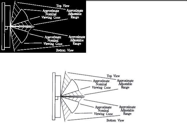
TN Fluid is the least expensive type. The viewing angle is about 40-45, and must be designated "top" or "bottom" view preference. Bottom view is used when the user will be below the plane perpendicular to the display, such as on a desk calculator. Top view is used when the display is mounted on a vertical surface below eye level. See diagram below.
TN Viewing Cone
STN AND NTN Fluid
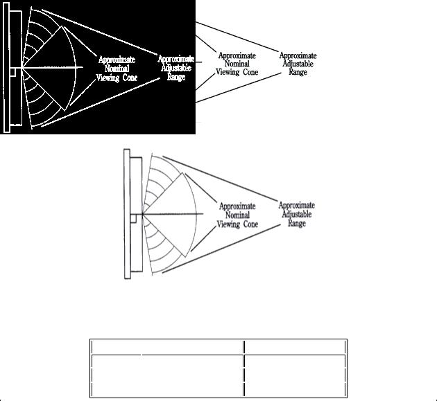
STN and NTN are both high contrast and wide viewing angle fluids. They differ in the level of contrast and viewing angle they achieve. Both can be seen above and below the plane perpendicular to the display. See the diagram below.
04/09/98
Application Notes for Character Mode LCDs |
Page 3 of 24 |
NTN Viewing Cone
STN Viewing Cone
The vertical viewing cone on all fluids can be adjusted by controlling the VO voltage. The range of adjustment is shown in the viewing angle charts below. The horizontal cone is relatively fixed.
Fluid Type Typical Contrast Ratio Typical Viewing Angle
TN |
3:1 |
40-45o |
NTN |
7:1 |
60o |
STN |
10:1 |
75o |
|
|
|
C. VIEWING MODES
The fluid type, polarizers and module construction determine the viewing mode and colour of the display. Displays are either "postive image", dark characters on a light background; or "negative image", light characters on a dark background. Backlight capability is determined by the presence or absence of a reflector or transflecter on the back side of the glass.
Reflective displays have a full reflector. The cannot be backlit. They offer the lowest power option and the best contrast in high ambient light conditions. They are not available in "positive image".
Transmissive displays are usually negative image and are backlit for best readability. They can be used in well lit indoor conditions to dark environments, typically not recommeded for daylight usage. They offer a different appearance than typical LCDs, bringing a light emitting look to the product.
Transflective displays combine the features of reflective and transmissive modes. These positive image displays can be read in all lighting conditions. The backlight can be turned on for low light levels or operated continuously to add the light-emitting look to a product.
04/09/98
Application Notes for Character Mode LCDs |
Page 4 of 24 |
Positive Image |
Negative Image |
Colors
TN positive image displays will have a silver/grey background and dark, almost black characters. In the negative image, the background will be black and the characters will be the color of the backlight, usually yellow/green or white. (See section on backlighting).
NTN and STN positive image displays can have a silver or yellow background with dark characters. Negative image versions have a dark blue background, characters are the folour of the backlight.
Choice of color is determined by what fits best in the package. Not all NTN displays are available in all colors. Consult Densitron for current availability.
D. BACKLIGHTING CHARACTER MODULES
Backlighting is used on LCDs to make them readable in low light conditions and to add te "pizazz" that a light-emitting display gives a product. Refer to the section on viewing modes for the types and applications of display that are backlit. Densitron currently uses 2 methods to backlight character LCD module: Electroluminescent (EL) and Light Emitting Diode (LED). Selection depends on desired color, available power, and required life.
1) EL Backlighting
EL backlighting is the original LCD backlight. It is thin, lightweight, low power, and fits between the glass assembly and PCB without any modification to the module. Most positive mode displays are furnished with a blue green lamp. Negative mode displays usually come with a white lamp. Other colors can be specially ordered.
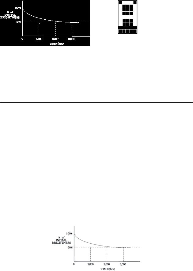
EL lamps operate from an AC power source, typically 400Hz at 70-110 VAC. Densitron supplies a full range of DC to AC inverters to power the lamps from a +5VDC source. There is no hard and fast rule for matching an inverter to a specific lamp. Lamp brightness and life are inversely proportional. That is the harder the lamp is driven the brighter it will be, but the shorter the life. Under rated operating conditions lamp life is about 2,000 to 2,500 hours to half its original brightness. Operating conditions such as temperature and humidity will also effect lamp life. The graph below illustrates the brightness vs life curve.
TYPICAL EL LAMP LIFE
Recommended inverters for various sizes of modules are shown below. Design considerations such as the operating conditions, desired brightness, required light, and lamp life must be balanced when designing with EL backlighting. For example, a negative transmissive display used in normal room lighting
04/09/98
Application Notes for Character Mode LCDs |
Page 5 of 24 |
may look better when driven with a larger inverter but useful life will be shortened.
Inverter Model |
Displays |
DAS5V4 |
All A/N Displays except 4x40, 2x40, LM300 & LM4700 Series |
DAS5V7 |
4x40, 2x40, LM300 & LM700 Series Transflective |
DAS5V8 |
4x40, 2x40, LM300 & LM700 Series Transflective |
|
Inverter Recommendations |
2) LED Backlighting |
|
LED backlighting offers a significant life advantage over EL lamps, but at the sacrifice of power and module size. Lamp life is in excess of 50,000 hours, and in most cases, 1 lamp failing does not make the backlight unusable. LED backlit does not make the backlight unusable. LED backlit modules are 2-4mm thicker than an EL or non-backlit module. Standard color is yellow-green. Red amber and other colors may be specially ordered.
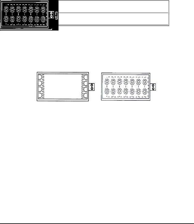
Edgelit Style |
Array Style |
LED Backlight Functional Diagram
Densitron offers two types of LED backlights; edgelit and array. Their basic format is shown above.
Edgelit can be used on modules up to 20 characters wide. Beyond 20 characters, the middle of the display begins to dim when compared to the edges. (The LM43X series uses a top mounted edgelight to achieve its balance of light and power). Edgelight is the lower power of the two types. The 4XXX series edgelit modules typically operate 30 to 60mA(at +5VDC) and come with a built in current limit resistor. The 43X series is somewhat higher and must have a limited resistor in series for proper operation.
Array backlighting produces a brighter and more even light. Power is the main consideration when designing with this type of module. It is not recommended for battery powered applications where the lamp will be on all the time. (It may be suitable for "on demand" applications).
Limit resistors must be used for array backlit modules and the LM43X series. Refer to the specific module specification for recommended and/or maximum backlight ratings. LEDs are arranged in serial pairs and operated in parallel (see diagram). The lamp will require 4.2VDC. Brightness can be set or controlled by selecting the proper limit resistor. Select a resistor that will drop the remaining voltage at the desired current. For example, if 200mA produces the desired brightness and the supply voltage is +5VDC, the limit resistor will drop 0.8VDC (5.0 - 4.2). Therefore, E/I = R = 0.8/0.2 - 4ohms.
Variable brightness can be controlled with a digital potentiometer or pulse-width modulated circuit.
II.HARDWARE DESIGN
A.POWER SUPPLY REQUIREMENTS
Modules require +5V at 1 to 10 milliamps. Extended temperature and some high contrast modules require -5V, also at low current. Inexpensive ICs convert +5V to -5V efficiently. If the display has backlighting, required power must also be budgeted. The power supply does not have to "lock-on" +5V but it must not "spike" beyond the module's absolute maximums.
A module's logic circuits have 3 connections to the power supply: VDD (+5VDC); VSS (Ground); and VO, viewing angle adustment, sometimes called contrast or bias control. The diagrams below show typical
04/09/98

Application Notes for Character Mode LCDs |
Page 6 of 24 |
connections. Contrast can also be controlled digitally with a digital potentiometer or DAC.
+5VDC Input LCD Module |
+/-5VDC Input LCD Module |
Power Supply to Module Connection
B. TEMPERATURE COMPENSATION
LCD modules have a limited operating temperature range. (See exact model for specific limits). The fluid within the glass is the most limiting factor. Over the rated range, the bias, or VO voltage required to optimise the contrast and maintain a constant viewing cone varies slightly. Compensation or adjustment can be achieved manually, with a tem-erature compensation circuit, or a combination of both.
Manual adjustment involves user accessible control via a potentiometer or digital device as explained above. A standard, negative temperature coefficient thermostat serves as an inexpensive, automatic sensor. It should be mounted as close to the glass as possible to get an accurate measurement. A thermistor circuit can be configured to provide automatic temperature compensations. Each module's specification lists approximate VO voltages required at the extremes of the temperature range and at 25C. A suggested circuit is shown below.
When operating outside of the module's rated temperature range, forced air and/or a heater are required to maintain reliable operation. The heater manufacturer can offer design assistance.
LCD Module
*For displays requiring -5VDC, R3 should be connected to -5, VSS to ground.
Temperature Compensation Circuit Example
Notes:
1)Typical termistor value 15k @ 25C, B=4300
2)R1 and R2 values are selected based on required VO level. See module specifications.
3)R1 and R2 can be variable resistor for manual control.
4)Vz value = 4.5V for1/8 & 1/11 duty cycle displays: 5.0V for 1/16 duty cycle; 10V for modules using +/- 5V supply.
C. INTERFACE
A/N modules are an intelligent peripheral which can communicate, bi-directionally, within the master system. Tie the device into the system data bus and treat it as RAM, I/O, or expanded, parallel I/O. The module is "selected" by gating a decoded, "module-address" output, with the host processor's "read or write" strobe. The resultant signal, applied to the LCDs "enable" input, clocks in data. There is no conventional "chip-select".
04/09/98

Application Notes for Character Mode LCDs |
Page 7 of 24 |
Interfacing the module to an existing micro-system involves:
a)joining the module to the host's data bus.
b)developing a "strobe" signal for the "E" signal
c)applying appropriate signals to modules "RS" and "R/W"
d)applying the proper "viewing angle" voltage to the display's VO pin.
Suggested interface circuits for most popular microprocessors are whoe on pages 16 and 17.
D. UNIQUE TIMING ASPECTS OF A/N LCDs
LCD modules provide a complete display subsystem which must be properly interfaced to the host microcomputer. The modules are classified as a "slow" periphera. Both access and strobe times exceed those normally encountered. A successful marriage requires strict attention in detail.
The Enable ("E") signal is the key signal line. This signal "clocks" the data and control signals into the LCD's internal microcontroller. The "E" signal must be a clean, positive going, digital strobe, which is active while data and control information are stable and true. The modules do not have a chip select line and so a decoded, host "select" signal must be geared with a proper strobe to generate this "E" signal. All module timing is referenced to specific edges of the "E" signal. The "E" signal is applied only when a specific module transaction is desired.
The "E" strobe must be 450 nS wide, minimum. It has a minimum period of 1000nS. The "E" line would only be pulsed this often during a "read" of the busy flag, performed during a "polled" display routine. Normally "E" strobes would be approximately 40 microseconds apart - which is the maximum display throughput. (See Instruction Table for complete list of execution times).
The 2 control lines, RS and R/W, must set-up 140 nS prior to the activation, or rise, of "E". These signals must remain stable, and hold for 10nS at the fall of "E". When a parallel port supplies RS, R/W and "E", do not allow these lines to all change together. This would result if a single instruction was employed and would surely violate the set-up requirement. Instead a second instruction must independently set the "E" bit high, after RS and R/W have been set. When the "E" signal is derived from a host strobe signal, it is only necessary to choose address or control signals which meet the 140nS demand. A single instruction transfer would be perfectly valid in this case - and is the goal.
When the host outputs RD and WR strobes these should not be linked to the module's R/W line. Since this same signal provides the "E" signal a set-up violation will occur. In this case it is preferable to use an address bit which sets-up earlier in the host's machine cycle. This is a crucial point.
The data bus must set-up 195 nS prior to the fall of "E". Atain these lines must hold for at least 10nS after "E" falls. Most host strobes should meet these requirements without difficulty.
The classic problem is encountered when the host micro is running so fast that the strobes are too narrow (450nS) to serve as the "E" pulse. In this case: a) prolong thewe pulses by using the host's "ready" input, b) prolong by employing that mode which extends timing, or c) decrease the host's crystal frequency.
When these options are not viable it will be necessary to latch both the data and control information and then activate the "E" signal.
Timing diagrams and suggested interfaces to various common microprocessors are in the appendix.
E. MOUNTING SUGGESTIONS
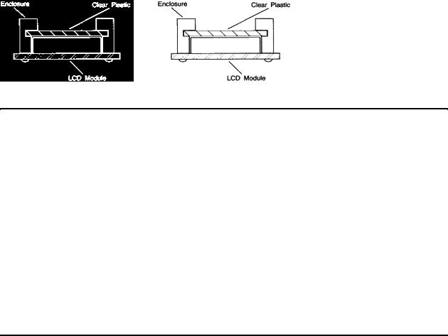
Care must be taken when mounting an LCD module to ensure that module is not stressed when installed and the surface is not exposed to scratches or harmful material.
Causing any kind of warp on the PCB of the module may product open columns or rows of dots, or intermittent display. Presure on the bezel from the top or against the bezel tabs will lead to similar
04/09/98
Application Notes for Character Mode LCDs |
Page 8 of 24 |
problems.
The front surface of the module is a sensitive plastic polarizer, not glass. Liquid must not be allowed to condense upon the device. Whenever possible, install an optically correct "protection Barrier" between the outside world and the display. This should be a non-polarized plastic or polycarbonate, which will reduce the incidence of foreign-object invasion and static discharge into the display. To keep glare at a minimum, mount the protective piece as close to the display surface as possible while preventing pressure on the piece from being transmitted to the LCD. Non-glare properties can be added to the protective piece at a slight loss of display clarity.
Mounting Suggestion
III.SOFTWARE REQUIREMENTS
A.INTRODUCTION
Software determines what, how and where data is displayed on the LCD. All Densitron character modules feature the Hitachi HD44780 or equivalent controller IC. This versatile chip features:
•Built-in character generator with 192 character modified ASCII character set.
•Ability to program up to 8 custom characters.
•Bi-directional 8 or 4 bit bus interface
•80 character RAM
•Automatic reset on power up
•Wide range of instruction functions including:
- Display clear, Cursor positioning, Display or cursor shift on data entry, and Display ON/OFF
Instructions are explained in detail on the following pages.
B. INITIALIZATION
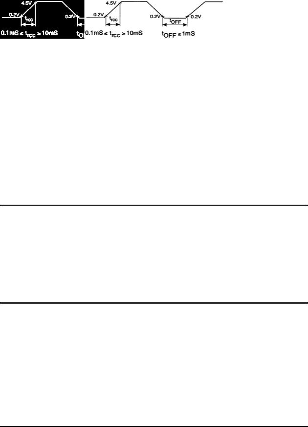
The module has 2 registers; one for inputting instructions and one for reading or writing data. Instructions are used to tell the module how and where to put the data. If the rise time of the power supply meets the criteria below, the module will default to the following functions via an internal initialization routine:
• |
Clear Display |
|
• |
Function Set |
DL=1: 8 bits interface |
|
|
N=0: 1 line display |
|
|
F=0: 5x7 dot font |
• |
Dislay ON/OFF control D=0: Display OFF |
|
|
|
C=0: Cursor OFF |
|
|
B=0: Blink OFF |
• |
Entry Mode Set |
I/O=1: +1 increment |
• |
DD RAM is selected |
|
The display will be busy for approximately 15mS after power ON.
04/09/98
Application Notes for Character Mode LCDs |
Page 9 of 24 |
Power Supply Timing Requirements for Internal Initialization
If power supply rise time cannot be assured of meeting the requirements above, or if different parameters are required (such as for a 2 line display), an initialization routine will have to be sent from the host. When first setting up the display, Densitron recommends the following initialization routines for 8 bit interfaces:
•1 line display with 5x7 font:
¡30, 30, 06, OE, 01 (hex)
•1 line display with 5x10 font:
¡34, 34 ,06 ,OE, 01 (hex)
•2 line display with 5x7 font:
¡38, 38, 06, OE, 01 (hex)
Wait states should be programmed to allow 15mS after power up before initialization begins. Waiting 4.1mS between the "3X" codes and 100S after the second "3X" code add a safety margin and ensure proper initialization.
After sending this routine, you should have a clear display with a flashing cursor in the upper left position. The cursor will then increment to the right with each data RAM write command. If, you do not have this display, see Troubleshooting Tips in the appendix.
C. 4-BIT OPERATION
The modules will operate from a 4-bit wide data bus. Data is transferred over data lines D7-D4. D3-D0 may float. 8-bit hex code is sent one nibble at a time, with the most significant nibble sent first. The function set in the initialization routine must change to accommodate this mode. A recommended initialization routine is as follows:
•2 line display with 5x7 font:
¡2, 8, 2, 8, 0, 6, 0, E, 0, 1(hex)
D.DISPLAY ADDRESSING
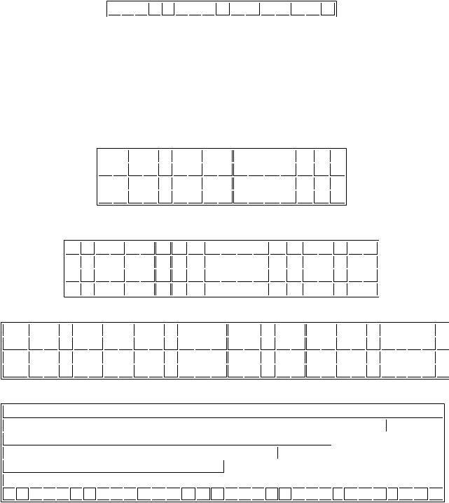
The display RAM is 8 characters. If the display is less than 80 characters, what is on the screen is a "window" on the RAM. What is displayed depends on the Entry Mode Set instruction. Address diagrams on the next page show RAM addresses as they appear after a Clear Display or Return Home instruction, or when Entry Mode Set instruction S=0.
If a 2-line display has less than 40 characters per line, the cursor will advance off the screen after the last character of the first line. To put data on the secone line, a Set DD RAM Address instruction must be sent.
When instruction S=1, the display is shifted. This makes the characters look as though they are marching across the screen on entry. It also lets small displays (2x16s, for example) to have data stored in nonvisible areas of the RAM and shifted in to view with one command. The last diagram shows how the addresses "wrap" in this mode.
E. SPECIALLY CODED DISPLAYS
Three types of displays have different addressing than typical 1 or 2 line displays. They are:
04/09/98
Application Notes for Character Mode LCDs |
Page 10 of 24 |
1.1 chip 1 line by 16 character displays
2.4 line by 16 or 20 character displays
3.4 line b 40 character displays
1 chip 1x16 - The HD44780 has the ability to control up to 16 characters without any other driver ICs. A lower cost 1 line by 16 character display can be manufactured to take advantage of this feature. To do this, it is necessary to initialize the display in the 2 line mode. The display is then addressed as a 2 line display. Line 1 addresses the first 8 characters; line 2, the second 8. When the cursor gets to the ninth character of the first line, it will "disappear" into undisplayed RAM (assuming no display shift). A Set DD RAM Address must be sent to reposition the cursor to the ninth displayed character which is logically the first position of the second line.
-------- 1 X 16 ----------
80 81 82 83 84 85 86 87 C0 C1 C2 C3 C4 C5 C6 C7
1 Chip 1x16 Addresses
4x40 - The maximum capacity of the HD44780 is 80 characters. The 160 characters on the 4x40 displays are accessed with 2 controllers. The first controller handles the top two lines; the second controller is conected to the bottom two lines. They share all I/O lines except the "E". Logically, the display is like two displays connected to the MPU as the "E" lines must be independent. Remember to turn off the cursor when moving from one half of the display to the other to avoid viewer distraction.
4x16/20 - Because of the way the controller and drivers are connected to make maximum use of their outputs, special attention must be paid to the addresses of these displays. Logically, line 3 follows line 1, and line 4 follows line 2. When the cursor gets to the end of line 1, it will jump to line 3. Keeping track of cursor location for proper positioning is important.
-------- 4 X 16 ----------
80 81 82 83 84 85 86 87 88 89 8A 8B 8C 8D 8E 8F
C0 C1 C2 C3 C4 C5 C6 C7 C8 C9 CA CB CC CD CE CF
90 91 92 93 94 95 96 97 98 99 9A 9B 9C 9D 9E 9F
D0 D1 D2 D3 D4 D5 D6 D7 D8 D9 DA DB DC DD DE DF
4 Line by 16 Character Addresses
-------- 4 X 20 ----------
80 81 82 83 84 85 86 87 88 89 8A 8B 8C 8D 8E 8F 90 91 92 93
C0 C1 C2 C3 C4 C5 C6 C7 C8 C9 CA CB CC CD CE CF D0 D1 D2 D3
94 95 96 97 98 99 9A 9B 9C 9D 9E 9F A0 A1 A2 A3 A4 A5 A6 A7
D4 D5 D6 D7 D8 D9 DA DB DC DD DE DF E0 E1 E2 E3 E4 E5 E6 E7
4 Line by 20 Character Addresses
Line1 80 81 82 83 84 85 86 87 88 89 8A 8B 8C 8D 8E 8F 90 91 92 93 94 95 96 97 ... A5 A6 A7
Line2 C0 C1 C2 C3 C4 C5 C6 C7 C8 C9 CA CB CC CD CE CF D0 D1 D2 D3 D4 D5 D6 D7 ... E5 E6 E7
Line3 80 81 82 83 84 85 86 87 88 89 8A 8B 8C 8D 8E 8F 90 91 92 93 94 95 96 97 ... A5 A6 A7
Line4 C0 C1 C2 C3 C4 C5 C6 C7 C8 C9 CA CB CC CD CE CF D0 D1 D2 D3 D4 D5 D6 D7 ... E5 E6 E7
4 Line by 40 Character Addresses
----- Complete RAM Addresses -----
1 x 40
1 x 24
1 x 20
1 x 16
1 x 8
80 81 82 83 84 85 86 87 88 89 8A 8B 8C 8D 8E 8F 90 91 92 93 94 95 96 97 ... A5 A6 A7 ... C5 C6 C7
1 Line Display Addresses
04/09/98