

Bologna / 04_TCAD_laboratory_pn_junction_GBB_20150223H1655
.pdfOutline
•Review of basic properties of the diode
Sentaurus Workbench setup (SWB)
•Implementation of Input files
–Sentaurus Structure Editor (SDE) command file
–Sentaurus Device (SDevice)
•command file
•parameter file
•Run the simulation
•Post-processing of results
G. Betti Beneventi 11

SWB: project tools & parameters (1)
OPEN SWB FROM THE LINUX COMMAND LINE swb &
STARTING (AND SAVING) A NEW SWB PROJECT
Project New New Project
Project Save as Project pn_ideale
ADD TOOLS
left click on No tools right click Add Name, scroll for Sde select Batch Ok left click on Sde right click Add Name scroll for Sdevice Ok
BATCH MODE MEANS “COMMAND FILE MODE”, i.e. NOT INTERACTIVE
ADD PARAMETERS (WITH THEIR DEFAULT VALUES): SDE /GEOMETRY AND DOPING Right click in the box below SDE tool
Parameter Add Parameter material default value Silicon Ok Right click on material Add Parameter Wp default value 10
IN SENTAURUS, THE GEOMETRICAL DIMENSIONS ARE INTENDED IN MICRON (=1x10⁻⁶ m) Right click on Wp Add Parameter Wn default value 50
Right click on Wn Add Parameter p_doping default value 1e16
IN SENTAURUS, DOPING IS INTENDED IN cm-3
Right click on p_doping Add Parameter n_doping1e16
ADD PARAMETERS (WITH THEIR DEFAULT VALUES): SDEVICE /MODELS AND VOLTAGES Right click in the box just below Sdevice tool SRH default value 0
FLAG FOR ACTIVATING SHOCKLEY-READ-HALL GENERATION-RECOMBINATION MODEL
G. Betti Beneventi 12

SWB: project tools & parameters (2)
Right click on SRH V_start default value -1
IN SENTAURUS VOLTAGE IS INTENDED IN VOLTS
Right click on V_start V_stop default value 1.5
ADD A NEW EXPERIMENT (A WHOLE LINE)
Experiments Add New Experiment material Germanium Apply Ok Experiments Add New Experiment material GaAs Apply Ok
EXPERIMENT RAMIFICATION
Left click just below the box p_doping of first line Nodes Extend Selection To Experiments Experiments Add Values Parameter p_doping Min. Value: 1e18 Step: 0 Number of values: 1 Apply Ok
CHANGING A SINGLE NODE VALUE
Left click on the box containing the n_doping value of the second row F6 1e18 enter
MAKING A TREE
Left click below SRH of first line Nodes Extend Selection To Experiment Experiments Add Values Parameter SRH Min. Value: 1 Step: 0 Number of values :1 Apply Ok
DONE SWB PART
G. Betti Beneventi 13

Outline
•Review of basic properties of the diode
•Sentaurus Workbench setup (SWB)
Implementation of Input files
–Sentaurus Structure Editor (SDE) command file
–Sentaurus Device (SDevice)
•command file
•parameter file
•Run the simulation
•Post-processing of results
G. Betti Beneventi 14
SDE: writing the command file (1)
OPEN A TEXT EDITOR FROM THE COMMAND LINE gedit &
File Save As sde_dvs.cmd
TYPE :
to include line of comment in the code
;*** IDEAL PN JUNCTION - sde_dvs.cmd ***
;*** INITIALIZATION ***
;clear structure
(sde:clear)
;New-replace-old option (default) (sdegeo:set-default-boolean "ABA")
;*** DEFINITIONS ***
;MATERIAL
(define material "@material@")
;define length (define L 50)
;p region thickness (define Wp @Wp@)
;region thickness (define Wn @Wn@)
;DOPING PARAMETERS
(define p_doping @p_doping@) (define n_doping @n_doping@)
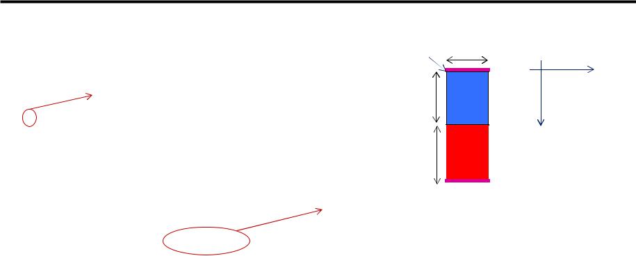
(0,0) L
x
Wp |
p |
|
Wn |
n |
y |
|
G. Betti Beneventi 15

SDE command file (2)
;MESH PARAMETERS (define xmax 10) (define xmin 0.1) (define ymax 1)
(define ymin 0.1)
;*** GEOMETRY ***
;convention: x=length y=thickness
;create p region
(sdegeo:create-rectangle (position 0 0 0) (position L Wp 0) material "p-region") ; create n region
(sdegeo:create-rectangle (position 0 Wp 0) (position L (+ Wn Wp) 0) material "n- region")
;*** CONTACTS ***
;a) SET VERTEXES
;1st vertex on p_contact (sdegeo:insert-vertex (position 0 0 0))
;2nd vertex on p_contact (sdegeo:insert-vertex (position L 0 0))
;1st vertex on n_contact
(sdegeo:insert-vertex (position 0 (+ Wn Wp) 0)) ; 2nd vertex on n_contact (sdegeo:insert-vertex (position L (+ Wn Wp) 0))
G. Betti Beneventi 16
SDE command file (3)
;b) SET EDGE (DECLARATION, ACTIVATION AND DEFINITION)
;p_contact
(sdegeo:define-contact-set "p_contact" 4 (color:rgb 1 0 0) "##") (sdegeo:set-current-contact-set "p_contact")
(sdegeo:define-2d-contact (find-edge-id (position (* L 0.5) 0 0)) "p_contact") ; n_contact
(sdegeo:define-contact-set "n_contact" 4 (color:rgb 1 0 0) "##") (sdegeo:set-current-contact-set "n_contact")
(sdegeo:define-2d-contact (find-edge-id (position (* L 0.5) (+ Wn Wp) 0)) "n_contact")
; *** DOPING ****
; p-region
(sdedr:define-constant-profile "p-doping-profile" "BoronActiveConcentration" @p_doping@)
(sdedr:define-constant-profile-region "p-doping-placement" "p-doping-profile" "p- region")
(sdedr:define-constant-profile-placement "p-doping-placement" "p-doping-profile" "p-doping-window")
; n-region
(sdedr:define-constant-profile "n-doping-profile" "PhosphorusActiveConcentration"
@n_doping@)
keyword for n-doping of EACH material
G. Betti Beneventi 17

SDE command file (4)
(sdedr:define-constant-profile-region "n-doping-placement" "n-doping- profile" "n-region")
(sdedr:define-constant-profile-placement "n-doping-placement" "n-doping- profile" "n-doping-window")
;*** MESH ***
;* WHOLE DOMAIN
(sdedr:define-refeval-window "domain-ref" "Rectangle" (position 0 0 0) (position L (+ Wn Wp) 0))
(sdedr:define-refinement-size "domain-ref-size" xmax ymax xmin ymin) (sdedr:define-refinement-placement "domain-ref-pl" "domain-ref-size" "domain-ref")
; * p-n JUNCTION REFINEMENT
(sdedr:define-refeval-window "junction-ref" "Rectangle" (position 0 (- Wp 0.050) 0) (position L (+ Wp 0.050) 0))
(sdedr:define-refinement-size "junction-ref-size" (/ xmax 10) (/ ymax 10) (/ xmin 10) (/ ymin 10))
(sdedr:define-refinement-placement "junction-ref-pl" "junction-ref-size" "junction-ref")
; * BUILDING MESH
(sde:build-mesh "snmesh" "-a -c boxmethod" "n@node@")
• Save Quit
means the current node
DONE SDE PART
G. Betti Beneventi 18

Outline
•Review of basic properties of the diode
•Sentaurus Workbench setup (SWB)
Implementation of Input files
–Sentaurus Structure Editor (SDE) command file
–Sentaurus Device (SDevice)
•command file
•parameter file
•Run the simulation
•Post-processing of results
G. Betti Beneventi 19
Sdevice: writing the command file (1)
*** PN JUNCTION - sdevice_des.cmd ***
File
{
**** INPUT FILES |
|
comment here is * and no more ; as it was in SDE! |
|
|
|
* geometry, contacts, doping and mesh |
||
Grid ="@tdr@" |
automatically get the _msh.tdr file of the experiment |
|
* physical parameters |
|
|
Parameter = "@parameter@" |
automatically get parameter file of the experiment |
|
****OUTPUT FILES
*to visualize distributed variables
Plot = "n@node@_des.tdr" distributed quantity (field, potential, carrier concentrations..)
* to visualize electrical characteristics at the electrodes Current= "n@node@_des.plt"
}
Electrode
{
*defines which contacts have to be treated as electrodes
*& initial boundary conditions
*obviously, electrode names must match the contact names of the
*sde_dvs.cmd file
{name="p_contact" voltage=0.0 }
{name="n_contact" voltage=0.0 }
}
G. Betti Beneventi 20