

ppl_05_e2
.pdfID: 3658
Customer: Oleg Ostapenko E-mail: ostapenko2002@yahoo.com
Customer: Oleg Ostapenko E-mail: ostapenko2002@yahoo.com
CHAPTER 11: STABILITY
Figure 11.7 Considered in isolation, a wing is dynamically unstable. The Centre of Pressure moves forward as angle of attack increases and the wing cannot return to equilibrium unless a balancing turning moment is applied to it.
227

Order: 6026
Customer: Oleg Ostapenko E-mail: ostapenko2002@yahoo.com
Customer: Oleg Ostapenko E-mail: ostapenko2002@yahoo.com
CHAPTER 11: STABILITY
The balancing turning moment, for an aircraft, is, of course provided by the tailplane, and we are now going to examine how the tailplane balancing moment works in fight. If you feel you need to revise the Principle of Moments before continuing, refer to Chapter 1, or refer to the appropriate chapter in the Mass and Balance section of
‘Aeroplanes’.
The Principle of Moments states that when a body is in equilibrium, or balance, the sum of the clockwise moments is equal to the sum of the anti-clockwise moments.
In Figure 11.8 you can see that although the weights of the two persons are different, the turning moments are equal because of the distance of each person from the pivot. As the turning moments are equal and opposite, the see-saw is in equilibrium.
To obtain balanced
flight the sum of all turning
moments about the C of G must balance.
Figure 11.8 Equilibrium is achieved when the anticlockwise moments equal the clockwise moments: (400 × 2)Nm = (800 × 1)Nm.
Now let us consider a wing and tailplane on a conventional aircraft. We depict the wing-tailplane system in Figure 11.9; the rest of the aircraft is not shown so that the illustration of the system can be kept as simple as possible.
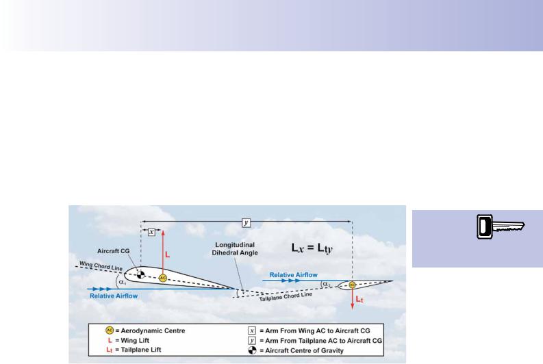
We have replaced the Centre of Pressure, through which the lift force acts, by a point called the Aerodynamic Centre. Lift from both the wing and the tailplane is shown acting through the Aerodynamic Centre. The Aerodynamic Centre is defned as the point through which aerodynamic forces act and which remains stationary at 25% of aerofoil chord. The Aerodynamic Centre is, for us, simply a convenient concept which prevents our having to think about a moving Centre of Pressure.
The Aerodynamic Centre (AC) of the wing is depicted at distance x, from the aircraft Centre of Gravity (C of G), and the AC of the tailplane is at the greater distance y, from the C of G.
The tailplane or horizontal stabilizer is much smaller than the main wing and, as such, produces a much smaller lift force. In the diagrams, the lift force produced by the wing is designated, L, and the lift from the tailplane Lt. Lt, though smaller than L, is, however, positioned at a greater distance from the aircraft’s C of G and, so, generates a stabilising moment in pitch.
228
ID: 3658
Customer: Oleg Ostapenko E-mail: ostapenko2002@yahoo.com
Customer: Oleg Ostapenko E-mail: ostapenko2002@yahoo.com
CHAPTER 11: STABILITY
Longitudinal Dihedral.
Note that the tailplane force needs to be downward to counter the wing’s pitching moment; the tailplane is thus an inverted aerofoil, or a symmetrical aerofoil with a slightly negative angle of incidence. It is usually mounted on the aircraft at a smaller angle of incidence (the angle between the mean chord line and the fuselage reference line) than that of the wing; the difference between the angles of incidence of wing and tailplane is called the longitudinal dihedral angle, and will have the effect of producing different angles of attack (or AoA or alpha) for wing and tailplane at any given relative airfow (RAF). RAF over the tailplane can also be affected by downwash (see last paragraph of this section and Figures 11.14 and 11.15).
The tailplane
or horizontal stabiliser gives
an aircraft longitudinal stability.
Figure 11.9 In level flight the tailplane moment equals the wing moment. Lx = Lt y
In Figures 11.9 to 11.13, the aircraft is assumed to be in straight and level fight with the same RAF for wing and tailplane, ignoring the effect of wing downwash. The aircraft is in longitudinal equilibrium with the wing moment Lx equal and opposite to the tailplane moment Lty, so that the two moments balance.
Effect of Longitudinal Dihedral.
We will now assume that the aircraft experiences a momentary gust from below or updraught, which causes the AoAs to change, increasing the wing AoA, and decreasing the tailplane AoA (or even possibly reversing the resultant force to an upforce). The wing’s lift will thus increase with a corresponding increase in nose-down moment (actually restricted by a small forward movement of the centre of pressure), but the tailplane’s downforce will be reduced or even reversed to positive lift, which enhances the nose-down movement. This has the effect of reducing the wing and tailplane AoAs eventually to their original stable values. A degree of damping in pitch is also provided by the change in AoA on the tailplane as the aircraft pitches down.
If the opposite happens (a gust from above or downdraught), the effects described above are reversed, and the aircraft pitches up to restore equilibrium. The aircraft thus demonstrates positive longitudinal stability.
In general, then, we may say that an aircraft’s longitudinal stability depends on the moments produced about the C of G of the aircraft, as a result of the aerodynamic forces produced at the wing and tailplane, indicated by L and Lt in Figure 11.10, and the distance from the C of G at which each force acts, indicated by x and y.
229

Order: 6026
Customer: Oleg Ostapenko E-mail: ostapenko2002@yahoo.com
Customer: Oleg Ostapenko E-mail: ostapenko2002@yahoo.com
CHAPTER 11: STABILITY
As C of G moves
forwards, an aircraft’s
longitudinal stability increases but manoeuvrability in pitch decreases.
Figure 11.10 The increase in wing lift and the decrease in tailplane downforce will tend to pitch the aircraft nose-down to restore the original state of equilibrium as in Figure 11.9.
The Effects of Centre of Gravity Movement on Longitudinal Stability.
The C of G of an aircraft is not fxed but varies according to such changing values as the weight (or mass) of the pilot, passengers, baggage and fuel load. It is, of course, not only their weight but also their position and distribution within the aircraft which will affect the C of G position. Remember that the C of G is the point through which acts the resultant of all the separate weight forces which make up the total weight of the aircraft.
Figure 11.11 Forward movement of the C of G increases static longitudinal stability.
Now consider Figure 11.11 which depicts the aircraft’s C of G as having moved forward. This has the effect of increasing both moment arms but reducing the proportional difference between them, and, compared with the situation shown in Figure 11.10, the correcting moment from the tailplane will be more effective. Thus, when the C of G moves forward, an aircraft’s longitudinal stability increases.
Since increased stability reduces manoeuvrability and decreases the effectiveness of the controls, a point must be reached where the forward position of the C of G will increase longitudinal stability to such an extent that the aircraft may not have
230

ID: 3658
Customer: Oleg Ostapenko E-mail: ostapenko2002@yahoo.com
Customer: Oleg Ostapenko E-mail: ostapenko2002@yahoo.com
CHAPTER 11: STABILITY
enough elevator authority to control the aircraft in pitch. If this were the case, the requirements for certifcation of the aircraft may no longer be able to be met and the aircraft would be dangerous to fy.
A limit will, therefore, be set for the forward position of the C of G. This limit will ensure the minimum requirement for aircraft manoeuvrability, and allow for proper response to the fight controls.
By the same process of reasoning, we may deduce that if the C of G is moved aft, longitudinal stability will reduce because the lever arm, y, will decrease in length and the tailplane will decrease in effectiveness.
Consequently, with the C of G near its aft limit, an aircraft is less stable longitudinally. With the C of G in this position, an aircraft will be very sensitive in pitch. The pilot would fnd that even a small displacement of the elevator would cause large pitching movements.
As the C of G moves further and further aft it reaches a position where the turning moment of the tailplane only just balances the turning moment of the wing. With the C of G in this position, called the neutral point, the aircraft would have neutral static longitudinal stability. If this were the case, and if any displacement in pitch occurred, the correcting moment of the tailplane would not be great enough to return the aircraft to its original pitch attitude. Because both the wing and tailplane moments would now be equal, the aircraft would remain in its new pitch attitude.
We see, then, that as stability decreases longitudinally, manoeuvrability increases, requiring reduced control movements by the pilot to control the aircraft. Advanced fghter aircraft often display this degree of manoeuvrability, with digitally-controlled systems to keep the aircraft stable during fight.
Centre of Gravity Limits.
If the C of G is moved even further aft than the neutral point, as depicted in Figure 11.12, the aircraft would become longitudinally unstable. For this reason an aft C of G limit, forward of the neutral point, is established and specifed by the aircraft designer, in order to ensure acceptable positive stability, and adequate controllability and manoeuvrability.
With a
C of G near the aft limit, an
aircraft is less
stable longitudinally and, thus, sensitive in pitch.
Figure 11.12 With the C of G further aft than the neutral point, the aircraft is longitudinally unstable.
231
Order: 6026
Customer: Oleg Ostapenko E-mail: ostapenko2002@yahoo.com
Customer: Oleg Ostapenko E-mail: ostapenko2002@yahoo.com
CHAPTER 11: STABILITY
The Pilot-in- Command
has a legal responsibility
to confirm that the C of G is within the prescribed limits before every flight.
Obviously, then, there will be a defned range of C of G positions, between the prescribed forward and aft C of G limits, for every aircraft (See Figure 11.13.). The C of G must lie at a point within this range at all stages of fight. The Pilot-in-Command has a legal responsibility to confrm that the C of G position lies within limits before every fight.
Figure 11.13 The C of G must lie within limits during all stages of flight.
In the take-off and landing
configuration longitudinal
stability can be reduced due to downwash.
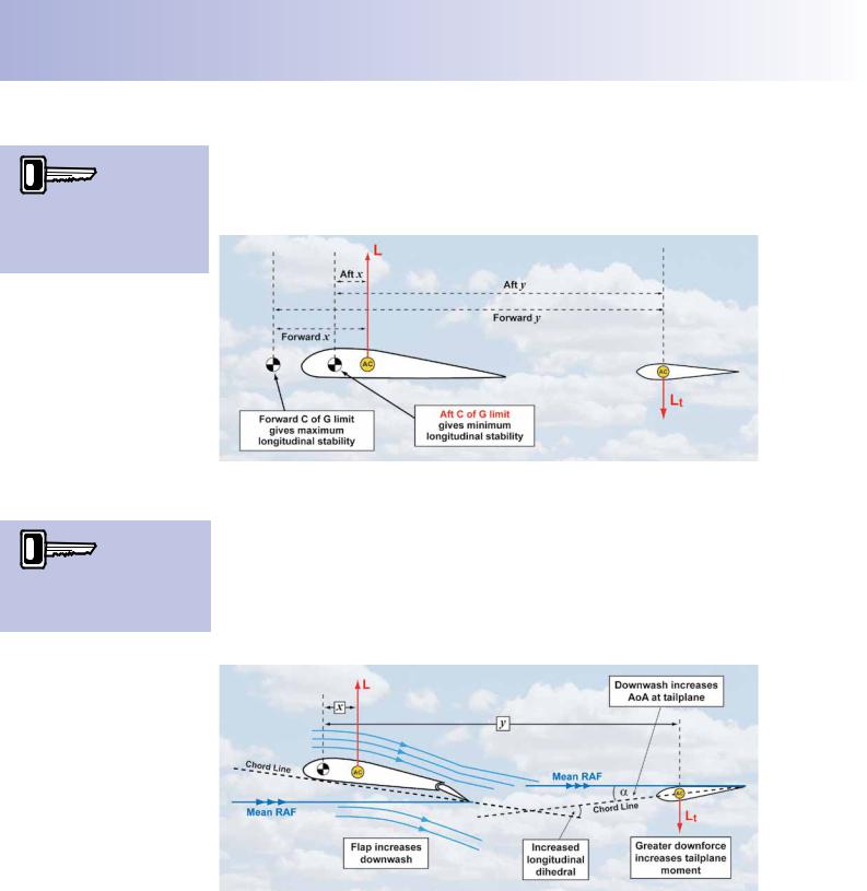
The Effects of Downwash on Longitudinal Stability.
So far in our examination of longitudinal stability, we have assumed that a gust affecting the aircraft in the pitching plane modifes the angle of attack of the wing and the tailplane to the same extent. However, any change in downwash due to, say, the lowering of fap or ground effect, will affect the tailplane AoA more than that of the wing. In Figure 11.14, with fap lowered, there is not only an increase in longitudinal dihedral due to the increased camber and incidence of the wing, but also an increase in AoA at the tailplane due to the greater downwash, both of which increase the longitudinal stability.
Figure 11.14 Increased downwash increases longitudinal stability.
When the aircraft comes into ground effect on landing, the downwash is fattened,
(see Chapter 5), and the AoA of the tailplane, and thus downforce, is reduced, whilst the net wing lift is slightly increased. This has the effect of altering the relationship between the wing and tailplane moments, reducing longitudinal stability (see Figure 11.14a). In Figure 11.14a, the increase in stability attributable to the change in longitudinal dihedral is counteracted by the reduction due to change in downwash.
Changes in downwash, for whatever reason, will affect the longitudinal stability of an aircraft.
232

ID: 3658
Customer: Oleg Ostapenko E-mail: ostapenko2002@yahoo.com
Customer: Oleg Ostapenko E-mail: ostapenko2002@yahoo.com
CHAPTER 11: STABILITY
Figure 11.14a Decreased downwash reduces longitudinal stability.
LATERAL STABILITY.
Lateral stability is stability in roll, about the longitudinal axis, which runs from nose to tail through the aircraft’s C of G, as depicted in Figure 11.15.
In this section, we will frstly examine lateral stability on its own, then we will consider how lateral stability and directional stability are inter-related.
If an aircraft is displaced in roll and tends to return to its original attitude without pilot input, the aircraft is said to possess positive lateral stability.
If an aircraft remains in its displaced position, after being disturbed in roll, it has neutral lateral stability.
If an aircraft has negative lateral stability, it will tend to continue to roll following the initial displacement.
Figure 11.15 Lateral Stability is stability in roll about the longitudinal axis.
Most light aircraft are designed to be stable in roll but not so stable as to cause handling diffculties for the pilot, particularly when manoeuvring close to the ground in gusty crosswinds. As a general rule, good handling qualities are obtained with approximately neutral lateral static stability. But most aircraft, if a bank angle is selected but not positively held, will eventually roll into a steeper banked attitude, leading to a spiral dive. This, of course, demonstrates negative static lateral stability.
Lateral stability is stability in the rolling plane about the
longitudinal axis.
233

Order: 6026
Customer: Oleg Ostapenko E-mail: ostapenko2002@yahoo.com
Customer: Oleg Ostapenko E-mail: ostapenko2002@yahoo.com
CHAPTER 11: STABILITY
The principal component of the aircraft which contributes to lateral stability is the wing. Other components do have an effect but are minor by comparison. To understand how the lateral stabilising forces are produced by the wing, we need to look at the changes to the airfow around the wing as the aircraft is displaced in roll.
When the aircraft rolls, the total lift force is inclined, as depicted in Figure 11.16. At any given angle of bank, we see, then, that lift no longer directly opposes weight. The resultant of weight and lift is a sideways force acting in the direction of the lower wing. The resultant force, therefore, causes a sideslip which generates a sideways component to the relative airfow in opposition to the direction of the sideslip.
On low-wing aircraft, wing dihedral helps provide lateral stability.
Figure 11.16 With an angle of bank selected, the aircraft will slip towards the lower wing.
While the roll is still taking place, the sideways component to the relative airfow will meet the down-going wing at a slightly greater angle of attack than the up-going wing. This action generates more lift on the down-going wing and tends to counter the rolling movement.
Note, however, that a straight wing displays this stability effect only when the aircraft is rolling. A straight wing, then, does not contribute greatly to lateral stability once the side slip is established.
Wing Dihedral.
Greater and longer lasting stabilising moments can be produced if the plane of each wing is angled positively, above a horizontal datum parallel to the lateral axis, as in Figure 11.17. This is called wing dihedral. The greater the dihedral, the greater will be the lateral stability.
Figure 11.17 Wing dihedral.
234

ID: 3658
Customer: Oleg Ostapenko E-mail: ostapenko2002@yahoo.com
Customer: Oleg Ostapenko E-mail: ostapenko2002@yahoo.com
CHAPTER 11: STABILITY
In order to examine how dihedral makes an aircraft more stable laterally, let us consider the wing on its own, as depicted in Figure 11.18.
Figure 11.18 A schematic drawing of wing dihedral.
How Wing Dihedral Contributes to Lateral Stability.
When a wing displaying positive dihedral is established in a sideslip, the sideways component of the relative airfow will meet the lower wing at a greater angle of attack than the upper wing (see Figure 11.19).
This fact has two principal consequences, both of which will cause the lower wing to generate greater lift than the upper wing, and so tend to return the aircraft to the wings-level attitude.
•The greater angle of attack at the lower wing increases that wing’s CL, and therefore its lift force, compared to the lift produced by the upper wing.
•The wing tip of the lower wing effectively becomes a leading edge. Consequently, the spanwise Centre of Pressure (CP) will now be nearer to the wing tip of the lower wing, causing the lower wing to generate more lift.
Wing dihedral
helps an aircraft to right itself
from a sideslip
because the relative airflow meets the lower wing at a greater angle of attack than the upper wing.
Figure 11.19 With dihedral the lower wing generates more lift in a sideslip.
Furthermore, depending on the position of the wing in relation to the fuselage, the upper wing will be shielded to some extent from the sideways component of the relative airfow. This fact will reduce the lift force on the upper wing, and add further to the aircraft’s lateral stability.
235

Order: 6026
Customer: Oleg Ostapenko E-mail: ostapenko2002@yahoo.com
Customer: Oleg Ostapenko E-mail: ostapenko2002@yahoo.com
CHAPTER 11: STABILITY
The Effect of Wing Position on Lateral Stability.
Low-Wing Aircraft.
Certain characteristics of low-wing aircraft tend to reduce lateral stability.
Because of the position of the low-wing in relation to the fuselage, the sideways component of the relative airfow caused by the sideslip fows down around the fuselage at this junction with the lower wing, decreasing its angle of attack, and fows up towards the higher wing increasing its angle of attack, as depicted in Figure 11.20.
Figure 11.20 Low wing aircraft posess characteristics which reduce lateral stability.
This characteristic of the airfow increases lift on the higher wing and decreases lift on the lower wing.
This phenomenon reduces lateral stability. However, other characteristics of lowwing aircraft add to lateral stability, even when there is no wing dihedral.
Figure 11.21 The keel surfaces above the C of G set up a restoring moment, adding to lateral stability.
236