

ppl_05_e2
.pdfID: 3658
Customer: Oleg Ostapenko E-mail: ostapenko2002@yahoo.com Customer: Oleg Ostapenko E-mail: ostapenko2002@yahoo.com
CHAPTER 5: DRAG
You met the two individual graphs earlier in this chapter. Figure 5.26, a combination of the two earlier graphs, shows that parasite drag predominates at high speeds, while induced drag at high speed is low. At low speeds, the opposite is the case. Based on the values for each of the individual graphs at various speeds, a curve may be drawn illustrating how the total drag acting on an aircraft varies with speed.
You should note that the speed at which the total drag acting on an aircraft is at a minimum is the speed at which parasite drag is equal to induced drag, (that is, the point at which the parasite drag and induced drag curves intersect each other). The speed for minimum drag is an important reference value for pilots. Minimum drag speed will give a pilot his aircraft’s maximum rate of climb , and, when considered with engine and propeller effciency, is an important factor in determining best speed for range in cruising fight.
Minimum drag speed is also the speed for the best lift/drag ratio. Each aircraft type will have a minimum drag speed which will vary, for that aircraft, depending on such factors as weight and wing loading. However, minimum drag speed will always occur at an angle of attack of approximately 4°.
Minimum drag
occurs when parasite drag
equals induced
drag, at an angle of attack of approximately 4°.
The Drag Equation.
Having derived a graph showing how total drag varies with airspeed, we can see from the graph (Figure 5.26) that total drag is high at both low and high speeds. In order to relate total drag to general aircraft parameters such as aircraft surface area, air density, wing shape, angle of attack and, of course, speed, aerodynamicists have derived the following drag equation:
Drag = CD ½ ρ v² S
You will notice that this equation is very similar to the lift equation that you have already met.
Lift = CL ½ ρ v² S
Like the Lift Equation, the Drag Equation is one of the few equations that you will be required to remember for the PPL theoretical knowledge examination.
In the Drag Equation, the symbols have the following meaning.
Learn the drag equation:
Drag = CD ½ ρ v² S.
CD |
is the Coeffcient of Drag which is a number which takes into account |
|
shape, as well the angle of attack of the relative airfow. CD has no units |
ρis the local air density; ρ has the standard units kg/m³
vis the aircraft’s true airspeed. Notice that total drag varies according to the square of the velocity. v has the standard units m/sec
S |
is a reference surface area. S has the standard units m² |
The Drag Equation, then, reveals that the total drag acting on an aircraft in fight is proportional to dynamic pressure, ½ ρ v², to the local air density, ρ, the reference surface area, S, and to the coeffcient of drag, CD, which takes into account the shape of the lifting surface and angle of attack of the relative airfow.
107

Order: 6026
Customer: Oleg Ostapenko E-mail: ostapenko2002@yahoo.com
Customer: Oleg Ostapenko E-mail: ostapenko2002@yahoo.com
CHAPTER 5: DRAG
The coefficient of drag, CD,
takes into account both
the shape of the wing and its angle of attack to the relative airflow.
The Drag Coefficient CD.
The drag coeffcient, CD, for total drag, has to include the effects of both parasite drag and induced drag and is determined experimentally. The reference surface area, S, can be any surface area chosen by the aerodynamicist: wing area, frontal area, or aircraft surface area. For different surface areas, the calculated CD will be different, but, of course, the measured total drag will be the same and the different values for CD will be related to each other as ratios of the different reference surface areas used.
For instance, let us assume that the reference surface area is the frontal cross sectional area of the whole aircraft. Now, in the equation Drag = CD ½ ρ v² S, the expression ½ ρ v² is the dynamic pressure, for which we have the symbol, Q. So, we can re-write the drag equation as:
Drag = CD Q S and we can, then, re-arrange this equation to read:
CD = |
Drag |
Q × S |
Force
Pressure = so Force = Pressure × Area, and
Area
Force produced by Dynamic Pressure = Q × S
We can see, then, that CD is an expression of the ratio of the drag force to the force produced by the dynamic pressure (Q × S). Being a ratio of quantities (i.e. forces) having the same units, CD itself has no units.
Note that the drag coeffcient, CD, for any given aircraft, is constant only while the aircraft maintains a constant angle of attack. As soon as the pilot selects a different angle of attack with respect to the relative airfow, the frontal area exposed to the airfow will change, the amount of turbulence generated will change, and, of course, the strength of the wing vortices will change. Therefore, CD will change.
Figure 5.27 shows how the drag coeffcient, CD, varies with angle of attack. Knowing the value of CD, and given the other variables in the drag equation, the total drag acting on an aircraft can be calculated for any given true airspeed from the drag equation: Drag = CD ½ ρ v² S
Figure 5.27 Graph of Coefficient of Drag, CD, against angle of attack.
108
ID: 3658
Customer: Oleg Ostapenko E-mail: ostapenko2002@yahoo.com Customer: Oleg Ostapenko E-mail: ostapenko2002@yahoo.com
The graph of CD against angle of attack shows that CD varies with varying angle of attack, being least at a very small positive angle of attack and rising at angles of attack greater and less than that angle. CD increases at quite a low rate up to about 8° but, from then on, increases more and more rapidly, especially as the stalling angle (typically about 16°) is reached. CD continues to rise rapidly beyond the stalling angle as the airfow becomes very turbulent.
CD is low at small angles of attack. Small angles of attack are, of course, associated with high speeds. So, although CD in the drag equation is small, v will be high, and, as drag is directly proportional to v², total drag will still be very high at high speeds, even though induced drag will be low. At high angles of attack, v is low, but, now, CD is very high. In straight and level fight, high angles of attack are associated with low speed. So, although parasite drag is low at low speed, total drag is high.
These fndings are what we were led to expect by the graph of total drag against speed, at Figure 5.27.
CHAPTER 5: DRAG
Total drag is high at both very low and very high airspeeds.
EFFECTIVE ANGLE OF ATTACK AND GROUND EFFECT.
To conclude this chapter on drag, we will look at how the additional downwash caused by wingtip vortices are affected by fight in close proximity to the ground.
This phenomenon is called ground effect. Ground effect, in modifying the wingtip vortices, also infuences induced drag and, consequently, the performance and handling characteristics of the aircraft. Ground effect is experienced by most pilots during the fnal phases of the landing.
Effective Angle of Attack or “D ownwash Angle”.
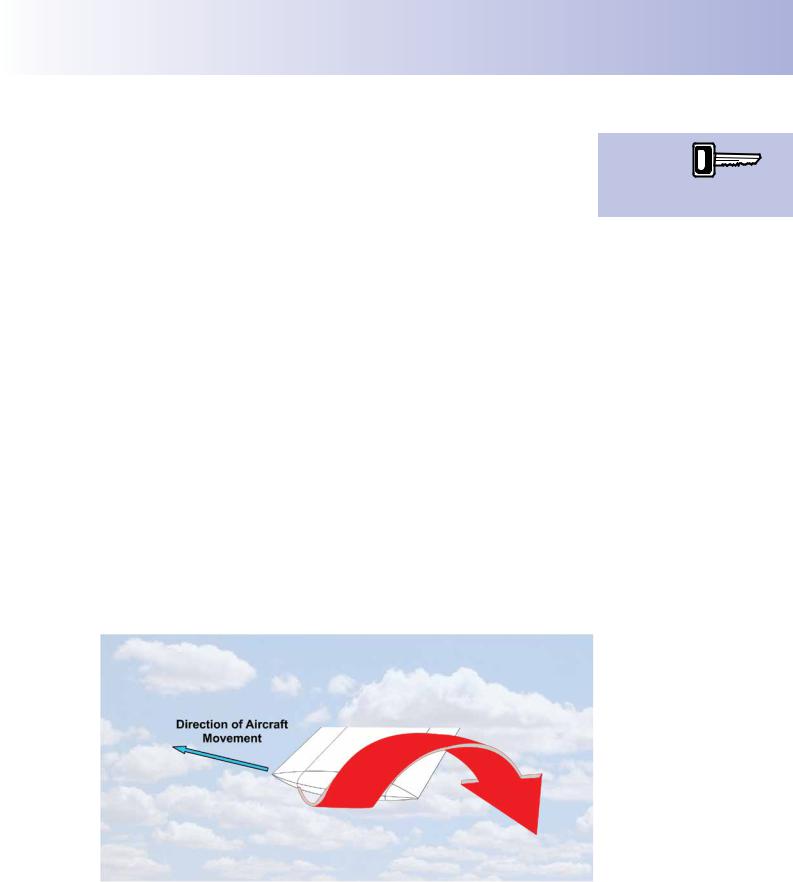
As you have learnt, wingtip vortices (see Figure 5.28), induce a downwash in the airfow over the wings which is additional to the main lift-essential downwash which we learnt about in the chapter on lift.
Figure 5.28 Wingtip vortices are the cause of the additional downwash which is the cause of induced drag.
In fact, the wingtip vortices, in increasing the angle of downwash aft of the wing, also modify the angle of upwash upstream of the wing, as depicted in Figure 5.29.
109

Order: 6026
Customer: Oleg Ostapenko E-mail: ostapenko2002@yahoo.com
Customer: Oleg Ostapenko E-mail: ostapenko2002@yahoo.com
CHAPTER 5: DRAG
Figure 5.29 Wingtip vortices are the cause of the additional downwash which is the cause of induced drag.
The effect of this modifcation of the airfow is to change the direction of the relative airfow to produce the true or effective airfow, as you can see from Figure 5.29. The result is a reduced angle of attack, measured between the wing chord and the effective airfow, and called the effective angle of attack.
Both the lift and the drag produced by the wing are affected by these changes.
Figure 5.30 Lift deficiency due to increased downwash angle.
The lift vector now acts at 90º to the effective airfow, as depicted by the red lift arrow in Figure 5.30.
In fact the effective lift vector, produced by the effective angle of attack, ae, now acts slightly rearwards. You can see, too, that, since the effective angle of attack has reduced, the magnitude of the lift force has reduced.
Lift must of course equal the weight of the aircraft to maintain level fight. So, to restore the lift which has been lost due to the downwash, as indicated in Figure 5.30, the wing must be selected to a higher angle of attack as in Figure 5.31.
110

ID: 3658
Customer: Oleg Ostapenko E-mail: ostapenko2002@yahoo.com Customer: Oleg Ostapenko E-mail: ostapenko2002@yahoo.com
CHAPTER 5: DRAG
Figure 5.31 A further increase in A of A restores the lift deficiency and generates induced drag.
This, as you now know, increases drag by a value that we call induced drag. The amount by which the angle of attack is reduced by the effective airfow, a - ae, is called the downwash angle.
Ground Effect.
When an aircraft is taking off or landing, the closeness of the wing to the ground prevents full development of the wingtip vortices, thus making them much weaker. This reduction in vortex strength is called ground effect. (Figure 5.32.)
Figure 5.32 Ground effect prevents full development of the wing tip vortices.
An aircraft is in
ground effect when within
approximately
½ a wing span’s distance from the ground.
An aircraft is subject to ground effect when it is within approximately half wingspan distance from the ground.
The reduction in vortex strength near the ground causes a decrease in the additional downwash angle and, consequently, an increase in the effective angle of attack, and an increase in lift.
Ground effect reduces induced drag and increases lift.
111

Order: 6026
Customer: Oleg Ostapenko E-mail: ostapenko2002@yahoo.com
Customer: Oleg Ostapenko E-mail: ostapenko2002@yahoo.com
CHAPTER 5: DRAG
Good speed
control on approach
helps to achieve a good landing.
Downwash modifies the airflow over the tailplane.
Figure 5.33 Ground effect modifies the effective angle of attack of the tailplane altering the aircraft’s stability and controllability in pitch.
Furthermore, even though the effective angle of attack has increased, the induced drag will decrease in ground effect due to the reduced wingtip vortices. This reduction in drag will cause the aircraft to tend to accelerate, and further increase lift.
The combination of ground effect and an approach fown at too high an airspeed, especially with a small fap angle selected, may lead to a balloon landing: a common trait of the student pilot. (See Figure 5.33.) For this reason, it is necessary for the pilot to demonstrate good speed control on the approach.
The Effect of Downwash on the Horiz ntal stabiliser.
We must also consider the effect of additional downwash on the horizontal stabiliser or tailplane. You will recall that it is the tailplane that provides stability and controllability of the aircraft in pitch.
Figure 5.34 Ground effect reduces the wingtip vortices and increases the effective angle of attack, thus increasing lift.
Downwash will affect the aerodynamic characteristics of the tailplane as well as the main wing. The effective angle of attack at the tailplane is modifed by the changing downwash from the main wing, altering the aircraft’s stability and controllability characteristics. Pilots will often fnd that an aircraft experiencing ground effect becomes less stable in pitch.
112

ID: 3658
Customer: Oleg Ostapenko E-mail: ostapenko2002@yahoo.com
Customer: Oleg Ostapenko E-mail: ostapenko2002@yahoo.comCHAPTER 5: DRAG QUESTIONS
Representative PPL - type questions to test your theoretical knowledge of Drag.
1.As airspeed increases, induced drag:
a.increases
b.decreases
c.is dependent on the weight of the aircraft
d.remains unchanged
2.As airspeed increases induced drag _____, parasite drag _____ and total drag _____.
a. |
increases |
increases |
increases |
b. |
increases |
decreases |
increases then |
|
|
|
decreases |
c. |
decreases |
decreases |
decreases |
d. |
decreases |
increases |
decreases then |
|
|
|
increases |
3.By changing the Angle of Attack of a wing, the pilot can control the aeroplane’s:
a.lift and airspeed, but not drag
b.lift, gross weight and drag
c.lift, airspeed and drag
d.lift and drag, but not airspeed
4.That portion of the aircraft’s total drag created by the production of lift is called:
a.parasite drag, which is greatly affected by changes in airspeed
b.induced drag, which is not affected by changes in airspeed
c.induced drag, which is greatly affected by changes in airspeed
d.parasite drag, which is inversely proportional to the square of the airspeed
5.If the Indicated Air Speed of an aircraft is increased from 50 kt to 100 kt, parasite drag will be:
a.four times greater
b.six times greater
c.two times greater
d.one quarter as much
6.Resistance, or skin friction, due to the viscosity of the air as it passes along the surface of a wing, is a type of:
a.induced drag
b.form drag
c.parasite drag
d.interference drag
113

Order: 6026
Customer: Oleg Ostapenko E-mail: ostapenko2002@yahoo.com
Customer: Oleg Ostapenko E-mail: ostapenko2002@yahoo.com
CHAPTER 5: DRAG QUESTIONS
7.How do Lift and Parasite Drag vary with airspeed?
a.lift and Parasite Drag both decrease as the square of the airspeed
b.lift decreases as the square of the airspeed while Parasite Drag increases as the square of the airspeed
c.lift increases as the square of the airspeed while Parasite Drag decreases as the square of the airspeed
d.lift and Parasite Drag both increase as the square of the airspeed
8.Parasite drag varies with:
a.the square of the airspeed
b.CLMAX
c.the airspeed
d.the weight of the aircraft, only
9.Choose one of the four options below to make an accurate statement. As airspeed increases:
a.induced drag increases
b.induced drag is unaffected
c.form drag decreases
d.induced drag decreases
10.Which of the following is the cause of wing tip vortices?
a.air spilling from the top surface to the bottom surface at the wing tip
b.air spilling from the bottom surface to the top surface at the wing tip
c.the increased form drag at the wing tip
d.the increased parasite drag at the wing tip
11.Wing tip vortices are caused by unequal pressure distribution on the wing which results in airfow from:
a.bottom to top round the trailing edge
b.top to bottom round the trailing edge
c.bottom to top round the wingtip
d.top to bottom round the wingtip
12.Which of the following is the correct formula for drag?
a.½ ρV² CL S
b.½ ρrV (CD)² S
c.½ ρ²V CD S
d.CD ½ ρV² S
114

ID: 3658
Customer: Oleg Ostapenko E-mail: ostapenko2002@yahoo.com
Customer: Oleg Ostapenko E-mail: ostapenko2002@yahoo.comCHAPTER 5: DRAG QUESTIONS
13.Choose the option below which best describes aircraft drag considerations as True Air Speed increases:
a.parasite drag decreases and induced drag increases
b.parasite drag increases and induced drag increases
c.parasite drag decreases and induced drag decreases
d.parasite drag increases and induced drag decreases
14.An aircraft carries out a given journey, on two separate days. On both days, the pilot fies at an indicated airspeed of 120 knots. On the frst day, the air density is greater than on the subsequent day. How will the forces of Lift and Drag acting on the aircraft compare on the two days?
a.on the frst day the Lift will be greater and Drag will be less than on the subsequent day
b.the forces of Lift and Drag acting on the aircraft will remain unchanged
c.on the frst day the Lift will be less and Drag will be greater than on the subsequent day
d.on the frst day both Lift and Drag will be less than on the subsequent day
Question |
1 |
2 |
3 |
4 |
5 |
6 |
7 |
8 |
9 |
10 |
11 |
12 |
|
|
|
|
|
|
|
|
|
|
|
|
|
|
|
Answer |
|
|
|
|
|
|
|
|
|
|
|
|
|
|
|
|
|
|
|
|
|
|
|
|
|
|
|
Question |
13 |
14 |
|
|
|
|
|
|
|
|
|
|
|
|
|
|
|
|
|
|
|
|
|
|
|
|
|
Answer |
|
|
|
|
|
|
|
|
|
|
|
|
|
The answers to these questions can be found at the end of this book.
115
Order: 6026
Customer: Oleg Ostapenko E-mail: ostapenko2002@yahoo.com Customer: Oleg Ostapenko E-mail: ostapenko2002@yahoo.com
116