

ppl_05_e2
.pdfID: 3658
Customer: Oleg Ostapenko E-mail: ostapenko2002@yahoo.com
Customer: Oleg Ostapenko E-mail: ostapenko2002@yahoo.com
CHAPTER 9: THE FOUR FORCES AND TURNING FLIGHT
TURNING FLIGHT.
We will now consider the distribution of fight forces in turning fight. Turning fight is also dealt with, especially in as far as wing loading is concerned, in the chapter dealing with Flight Limitations. For the Principle of Flight considerations of turning fight, we need only depict, in our diagrams, two of the principal fight forces, lift and weight, though we shall make mention of thrust and drag. Consequently, the diagrams associated with the following explanation will show the aircraft viewed from the front.
You have learnt that in steady, straight fight, (straight and level, climb or descent) all the fight forces are in equilibrium with no out-of-balance resultant force acting on the aircraft. It is important that we understand that equilibrium is a necessary situation for straight fight at constant speed, whether the aircraft is straight and level, or in a straight climb or descent. With the aircraft in a state of equilibrium, there may well be resultant forces to consider, as we have seen. But, for equilibrium to exist, if there are resultant forces, they must balance each other out.
Straight fight at constant speed, then, requires equilibrium. This situation accords with Newton’s 1st Law which teaches us that a body will remain in its state of rest or uniform motion in a straight line unless acted upon by an out-of-balance force. In straight fight, there is no out-of-balance force acting on the aircraft, and, no matter how high or low the speed at which the aircraft is fying, the pilot feels no force acting on him except his normal weight. (Weight is, in fact, an acceleration, as you have learnt in the chapter on Mass and Weight; that is why we can always feel it; but we will leave that complication aside for the moment.)
But if we want to change the straight fight path (i.e. change direction) or the speed of an aircraft, an out-of-balance force must be applied to the aircraft.
(You will remember that we said that although in a straight climb at constant speed the forces are in equilibrium, an initial out-of-balance force, usually a coordinated increase in thrust and angle of attack, is required to initiate the climb.
Centripetal Force.
It will be clear to you that when a body is turning in a circular path, it is constantly changing direction. Consequently, the forces acting on a body which is following a circular path are not in equilibrium. In circular motion, there must be an out-of-balance resultant force acting towards the centre of the circle, or else the body would be moving in a straight line in accordance with Newton’s 1st Law. This out-of-balance force is called by scientists a centripetal force. (See Figure 9.10). Centripetal is derived from Latin and means centreseeking.
For an aircraft in turning fight, the centripetal force has to be supplied by
Figure 9.10 For a body to travel in a circular path, it must constantly change direction under the influence of an out-of-balance force called “centripetal force”.
187

CHAPTER 9: THE
In level turning flight, the total
lift generated by the wings
must increase to provide the centripetal force for the turn as well as to counteract the aircraft’s weight.
Order: 6026
Customer: Oleg Ostapenko E-mail: ostapenko2002@yahoo.com
Customer: Oleg Ostapenko E-mail: ostapenko2002@yahoo.com
FOUR FORCES AND TURNING FLIGHT
the lift force being directed towards the centre of the turn. That is why, in order to turn, a pilot must apply bank in the direction of turn. That part of the lift force which then provides the centripetal force constantly changes the direction of fight of the aircraft, and, because centripetal force is an out-of-balance resultant force, the pilot feels it as an apparent increase in weight. What is actually happening is that the centripetal force is accelerating the mass of the aircraft towards the centre of the circle, but because the aircraft’s linear velocity (its airspeed) is superimposed on the acceleration towards the centre of the circle, the aircraft does not move towards the centre of the circle but instead describes a circular path at a constant distance, or radius, from the centre. This acceleration, not surprisingly called centripetal acceleration, acts on all the individual masses of components, equipment and crew which are part of the aircraft.
Figure 9.11 A 45° banked turn. The lift generated by the wings must both support the aircraft’s weight and provide the turning (centripetal) force.
Now, the only force that a pilot has at his disposal to provide the centripetal force for a turn is the lift from the wings. That is why, in order to turn, the pilot applies an appropriate amount of bank in the direction in which he wishes to turn. Figure 9.11 illustrates a 45° banked turn. In your private pilot training, a 45° banked turn is probably the steepest you will be asked to fy.
In the 45°-banked turn illustrated, the total lift force, LT, has to do two jobs. LT is not only causing the aircraft to turn but is also supporting the weight of the aircraft (which continues to act vertically downwards) so as to maintain the aircraft in level fight.
To achieve both these objectives, the total lift force in the turn needs to be greater than that required for straight and level fight. In Figure 9.11, as in the following two diagrams, the blue lift arrow depicts the magnitude of the lift required to maintain the aircraft in straight fight, and the red arrow depicts the extra lift that the wings must generate to enable the aircraft to turn while maintaining its altitude.
If level fight is to be maintained, as the angle of bank is increased, the angle of attack
(and, therefore, CL) of the wing must also be increased by a progressive backward movement of the control column. This increases the lift force (Lift = CL ½ ρv2 S) to a value, LT, such that the vertical component, LV, of the total lift is suffcient to balance the aircraft’s weight and maintain level fight, while the horizontal component of the total lift, LH, provides the centripetal force required to turn the aircraft.
188

ID: 3658
Customer: Oleg Ostapenko E-mail: ostapenko2002@yahoo.com
Customer: Oleg Ostapenko E-mail: ostapenko2002@yahoo.com
CHAPTER 9: THE FOUR FORCES AND TURNING FLIGHT
Airspeed in the Turn.
To the pilot, the increase in angle of attack required to generate the extra lift for the turn will be apparent as an increase in the back pressure on the control column suffcient to maintain the correct attitude and constant altitude. However, as the back pressure increases, and with it the angle of attack, CD naturally increases, along with CL, causing the total drag to rise (Drag = CD ½ ρv2 S). The increased drag will naturally lead to a reduction in airspeed, if thrust is not increased. While the reduction in speed is small in a medium level turn, up to 30° angle of bank, and may be acceptable, this would not be the case in a 45°-banked turn, or above. In a 45°- banked turn, it is important to increase thrust to maintain the entry speed because of the increased stalling speed. You will learn more about stalling speed in turns in the relevant chapters of this book, though, for your interest, we include in the diagrams the stalling speed for the angles of bank illustrated. For instance, in a 45°-banked turn, the stalling speed of a PA28 Warrior is around 60 knots, 10 knots higher than its straight fight stalling speed of 50 knots
Load Factor.
In a 45°-banked turn, the lift force required to generate the necessary centripetal force and centripetal acceleration for the turn is 1.41 times the magnitude of the aircraft’s weight. The pilot will clearly sense this increase in force, which is also acting on him, as an inertial reaction to the increase in lift. In fact, the whole of the aircraft structure will be subjected to the inertial reaction to the increase in lift generated by the wings, and sense this reaction as an increase in load factor (often referred to as ‘G’). As you will learn in later chapters, it is the increased wing loading caused by the higher load factor which causes the increase in stalling speed in a turn (the derivation of the value of load factor is covered on Page 296).
In a correctly fown turn, the pilot will feel the extra lift force as an apparent increase in weight pressing him frmly into his seat. In a 60°-banked turn, the lift force required for the turn is twice the magnitude of the aircraft’s weight, and the pilot actually feels that his own weight has doubled; he is ‘pulling 2G.’ (See Figure 9.12).
An aircraft’s stall speed increases during turning flight.
The inertial
reaction to the increased lift
force required
to maintain a level turn is called the Load Factor.
In a turn, stall speed =
straight & level stall speed × stttttttttttttLoad Factor.
Figure 9.12 A 60° banked turn. The lift required for the turn is twice its straight flight value. Load Factor is 2, and the stalling speed is 71 knots.
189
Order: 6026
Customer: Oleg Ostapenko E-mail: ostapenko2002@yahoo.com
Customer: Oleg Ostapenko E-mail: ostapenko2002@yahoo.com
CHAPTER 9: THE FOUR FORCES AND TURNING FLIGHT
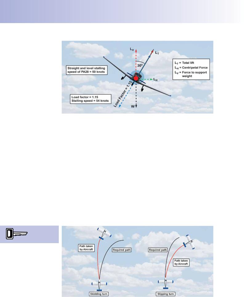
Figure 9.13 A 30° banked turn. The lift required for the turn is 1.15 times its straight flight value; Load Factor is 1.15, and the stalling speed is 54 knots.
In a 30°-banked turn, on the other hand, the lift required to produce the centripetal force to make the aircraft turn is only 1.15 times the straight-fight lift force. The pilot may not sense this small increase of apparent weight at all. (See Figure 9.13).
The B“ alanced” Turn.
You will learn from your fying instructor how to turn at different angles of bank, and at different airspeeds. During turning exercises, you may well notice, if you do not fy the turn correctly and “keep the ball in the middle”, that the out-of-balance force required to make the aircraft turn causes you to slide on your seat either into or out of the turn. If this does happen, your instructor may urge you to fy a “balanced” turn.
You may well wish to ask him what he means by “balanced” if the force required to produce the turn, in the frst place, is an “out-of-balance” force. The answer will lie in the specialist meaning of “balanced” in the instructor’s patter, but the question may make for an interesting conversation in the club house, debriefng room or bar.
Skidding and Slipping Turns.
During turning manoeuvres, uncoordinated use of the aileron and rudder may cause the turn to be unbalanced. In an unbalanced turn, the aircraft will either slip or skid through the air, while it is turning. Figure 9.14, illustrates the difference between
‘Skid out, slip in’.
Figure 9.14 The path of a skidding turn and a slipping turn.
190

ID: 3658
Customer: Oleg Ostapenko E-mail: ostapenko2002@yahoo.com
Customer: Oleg Ostapenko E-mail: ostapenko2002@yahoo.com
CHAPTER 9: THE FOUR FORCES AND TURNING FLIGHT
slip and skid. Basically, for a given radius of turn at a given speed, there is only one correct angle of bank. If an aircraft is overbanked for its turn, or if the pilot has applied too little rudder, the aircraft will slip into the turn. On the other hand, if the pilot has applied to small an angle of bank for the turn, or used too much rudder, the aircraft will skid out of the turn.
Co-ordination of Turns - Slip and Skid.
Slip and skid is displayed by the inclinometer which is the bottom portion of the
‘turn co-ordinator’, or the ‘turn and slip’ indicator. (See Figure 9.15.) The inclinometer consists of a glass tube flled with liquid, and contains a ball.
Figure 9.15 The Turn and Slip Indicator and Turn Co-ordinator, showing a balanced rate one turn.
Figure 9.15 indicates a turn to the right. Because the ball is in the middle the pilot sees that his turn is perfectly balanced, with no slip or skid present. If the aircraft were skidding out of the right turn, as depicted in Figure 9.16, the ball would be displaced to the right.
Figure 9.16 The ball indicates a skid away from the right turn.
The skid may have been caused because rudder had wrongly been applied to the left; the simple rule to re-balance the turn is to “step on the ball”, i.e. apply suffcient right rudder to return the ball to the middle position, between the two vertical lines.
191

Order: 6026
Customer: Oleg Ostapenko E-mail: ostapenko2002@yahoo.com
Customer: Oleg Ostapenko E-mail: ostapenko2002@yahoo.com
CHAPTER 9: THE FOUR FORCES AND TURNING FLIGHT
Figure 9.17 The ball indicates a slip towards from the direction of turn.
If the aircraft were slipping in to the turn to the right, as in Figure 9.17, the ball would be displaced to the left. It could be that there is much rudder for the rate of turn being fown, and the easiest solution to return the ball to the middle is to apply left rudder. This amounts to the same thing as reducing right rudder. The simple answer, though, as before, is to “step on the ball.”
During a Rate One turn,
an aircraft changes
direction at a rate of 3° per second or 360º in 2 minutes (hence the caption on a turn indicator/coordinator).
Rate of Turn, Airspeed and Centripetal Force.
The magnitude of the centripetal force required to turn an aircraft varies with both airspeed and rate of turn. (The rate of turn is a measure of the time taken to complete a full 360° turn.) If the rate of turn is doubled (that is, with half the radius of turn) while maintaining a given airspeed, the centripetal force required to execute the turn is also doubled. If the airspeed were doubled but the rate of turn were to remain the same (constant radius), the centripetal force would need to be four times as great. The basic mathematical formula behind these statements is shown in Figure 9.18. The formula expresses the mathematical relationship between centripetal force, FCP, the radius of turn (i.e. rate of turn), the mass of the body which is travelling in the circular path, and its linear velocity.
Figure 9.18 Mathematical relationship between centripetal force, FCP, the radius of turn (i.e. rate of turn), the mass of the body, and the linear velocity, v.
192

ID: 3658
Customer: Oleg Ostapenko E-mail: ostapenko2002@yahoo.com
Customer: Oleg Ostapenko E-mail: ostapenko2002@yahoo.com
CHAPTER 9: THE FOUR FORCES AND TURNING FLIGHT
In civil fying, procedural turns are carried at a rate of 180° per minute, or 3° per second. This rate of turn will be indicated on an aircraft’s Turn and Slip Indicator and termed as a rate one turn. At normal light aircraft cruising speeds, a rate one turn will not require a centripetal force which will cause you any discomfort; a rate one turn at 90 knots would require, for instance, only 16° of bank.
The rate at which any aircraft turns is determined by true airspeed and angle of bank. At a given true airspeed, a given angle of bank will provide a certain rate of turn. A simple way to estimate the angle of bank required for a rate one turn of 3° per second, at a given true airspeed, is to take 10% of the true airspeed in knots, and add 7; for example, at 100 knots, a rate one turn is achieved with 17° angle of bank.
Note, too, the general rule that, in a turn at constant airspeed, if the angle of bank is increased, the rate of turn will increase i.e. the radius of the turn will become smaller. If, at constant angle of bank, the airspeed is decreased, the rate of turn will increase (i.e. the radius of the turn will become smaller); if the airspeed is increased at constant angle of bank, the rate of turn will decrease, (i.e. the radius of the turn will get larger). You can fgure all this out mathematically, if you wish, from the formula in Figure 9.18. Just remember that an increased angle of bank will increase the centripetal force, FCP.
The Pilot’s Control of the Turn.
Once established in a turn, at a desired airspeed and angle of bank, the pilot can easily control the turn, especially one of low bank angle, using aileron and rudder to maintain angle of bank, and elevator (or stabilator) to control attitude (CL) and altitude. At steeper angles of bank, throttle must also be used to maintain speed because of the increased drag. But this aspect of your PPL studies belongs properly to fying instruction.
THE PROPELLER SLIPSTREAM.
In addition to the principal fight forces, and the tailplane force, the propeller slipstream will also generate an aerodynamic force on the fn (or vertical stabiliser) which acts in the yawing plane. The propeller converts engine power to thrust. It does this by accelerating the air and moving it rearwards. This movement of air is called the propeller’s slipstream which moves in a helical path behind the propeller.
To determine the angle of bank, in
degrees, for a
Rate One turn, divide the True Airspeed in knots by 10 and add 7.
At constant angle of bank, if airspeed is
increased, rate
of turn is decreased and vice versa.
Figure 9.19 With a clockwise rotating propeller (as viewed by the pilot), increasing power will cause the aircraft to yaw to the left.
193

CHAPTER 9: THE
When the pilot increases
power, the aircraft wll tend to yaw in the opposite
direction to the propeller rotation. When power is reduced, the yaw will be in the direction of propeller rotation.
When
increasing or decreasing power, the
pilot must prevent yaw, and maintain balanced flight
by applying rudder in the appropriate direction.
Order: 6026
Customer: Oleg Ostapenko E-mail: ostapenko2002@yahoo.com
Customer: Oleg Ostapenko E-mail: ostapenko2002@yahoo.com
FOUR FORCES INCLUDING TURNING FLIGHT
The propeller slipstream meets the fn (vertical stabiliser) in such a way that it induces a yawing moment on the aircraft which is opposite to the direction of rotation of the propeller. Consequently, variations in throttle setting will cause an aircraft to yaw in a direction which depends on the direction of propeller rotation. See Figure 9.19, previous page.
If the propeller rotates to the right, or clockwise, when viewed from the cockpit, inducing a yaw to the left, the aircraft will tend to swing to the left if power is increased. Conversely, the aircraft will tend to swing to the right if power is decreased.
The effect of the yawing moment can be counteracted by offsetting the fn (vertical stabiliser). This will create an aerodynamic force in opposition to the yawing moment caused by the slipstream. The offset is usually such that the rudder is neutral at cruising speed and power.
Effect of Power Variations on Yaw.
As we have mentioned, the turning moment caused by the slipstream will obviously be affected by increases and decreases of power. So, on increasing and decreasing power, the pilot must apply rudder in the appropriate direction to prevent yaw and maintain balanced fight.
194

ID: 3658
Customer: Oleg Ostapenko E-mail: ostapenko2002@yahoo.com
Customer: Oleg Ostapenko E-mail: ostapenko2002@yahoo.com
CHAPTER 9: THE FOUR FORCES INCLUDING TURNING FLIGHT QUESTIONS
Representative PPL - type questions to test your theoretical knowledge of The Four Forces - Turning Flight.
1.If the throttle is moved to adjust the power in level fight, the resulting change in propeller slipstream will primarily affect:
a.the aircraft’s trim in the pitching and yawing planes
b.the aircraft’s trim in the rolling plane
c.the longitudinal stability
d.the lateral stability
2.Which of the four options below most accurately describes the relationship between the forces acting on an aircraft in fight for those forces to be in equilibrium?
a.Lift equals drag, and thrust equals weight
b.Lift equals weight, and thrust equals drag
c.Lift equals thrust plus drag
d.Lift equals thrust, and weight equals drag
3.An aircraft has a nose down pitching moment due to the lift / weight couple and a nose up pitching moment due to the thrust / drag couple. When power is increased:
a.it will pitch nose up
b.it will pitch nose down
c.the couples both increase in magnitude but remain balanced
d.the couples both decrease in magnitude but remain balanced
4.In straight and level powered fight the following principal forces act on an aircraft:
a.thrust, lift, weight
b.thrust, lift, drag, weight
c.thrust, lift, drag
d.lift, drag, weight
5.Considering the forces acting upon an aeroplane, at constant airspeed, which statement is correct?
a.Weight always acts vertically downwards towards the centre of the Earth
b.Lift acts perpendicular to the chord line and must always be greater than weight
c.Thrust acts parallel to the relative airfow and is always greater than drag
d.The lift force generated by the wings always acts in the opposite direction to the aircraft’s weight
195

Order: 6026
Customer: Oleg Ostapenko E-mail: ostapenko2002@yahoo.com
Customer: Oleg Ostapenko E-mail: ostapenko2002@yahoo.com
CHAPTER 9: THE FOUR FORCES INCLUDING TURNING FLIGHT QUESTIONS
6.The tailplane or horizontal stabilizer usually provides a downwards load in level fight because:
a.the main-plane lift is always positive
b.the lift/weight and thrust/drag couples combine to give a nose down pitch
c.the lift produced is greater than required at high speed
d.this confguration gives less interference
7.Scientifcally speaking, an aircraft’s mass is a measure of:
a.its weight
b.how big it is
c.how much matter it contains
d.its volume
8.An aircraft rotates about:
a.its wings
b.its centre of gravity
c.its main undercarriage
d.its rudder
9.In a steady gliding descent, assuming zero thrust from the propeller, the three forces acting on the aeroplane are weight, lift and drag. These three forces are in equilibrium, but:
a.weight and lift are the same
b.weight is greater than lift
c.weight is less than lift
d.weight and drag are the same
10.If an aircraft increases speed while maintaining a constant angle of attack with its wings:
a.the lift generated by its wings will remain constant but total drag will increase
b.the lift generated by its wings will decrease and total drag will increase
c.the lift generated by its wings will increase but total drag will remain constant
d.both the lift generated by its wings and total drag will increase
11.Complete the following sentence to make the most correct statement.
In a steady, unaccelerated climb, the four forces acting on the aeroplane (weight, lift, thrust and drag) are in equilibrium, but:
a.lift is greater than weight
b.lift is equal to weight
c.thrust is equal to aerodynamic drag
d.lift is less than weight
196