

ppl_06_e2
.pdfCustomer: Oleg Ostapenko E-mail: ostapenko2002@yahoo.com
CHAPTER 2
LANDING GEAR, TYRES
AND BRAKES
23

Order: 6026
Customer: Oleg Ostapenko E-mail: ostapenko2002@yahoo.com
Customer: Oleg Ostapenko E-mail: ostapenko2002@yahoo.com
CH AP T ER 2 : LANDING G EAR , T Y R ES AND BR AK ES
24

ID: 3658
Customer: Oleg Ostapenko E-mail: ostapenko2002@yahoo.com
Customer: Oleg Ostapenko E-mail: ostapenko2002@yahoo.com
CH AP T ER 2 : LANDING G EAR , T Y R ES AN
FUNCTIONS OF THE LANDING GEAR.
The functions of the landing gear are, firstly, to provide a means of manoeuvring the aircraft on the ground, secondly, to support the aircraft at a convenient height to give clearance for propellers and flaps, etc, and, thirdly, to absorb the kinetic energy of landing.
Figure 2.1 A Warrior aircraft taxying.
La n d i n g G e a r De s i g n .
Once airborne, the landing gear serves no useful purpose and is dead weight. It would be ideal to replace the landing gear with some ground based equipment for use before the aircraft takes off. But, while it is possible to achieve manoeuvring and support for the aircraft with ground based equipment, no satisfactory alternative exists for absorbing the kinetic energy of landing
and providing a means of controlling deceleration. For this reason, a vast amount of research has gone into the design of undercarriage units in order to reduce their weight and their stowed volume when retracted.
LANDING GEAR TYPES - FIXED OR RETRACTABLE.
With slow, light aircraft, and some larger aircraft on which simplicity is of prime importance, a fixed, non-retractable landing gear is often fitted. On light, training aircraft, for instance, the reduced performance caused by the drag of the fixed landing gear during flight is offset by its simplicity, its reduced maintenance and also its low initial cost. On high speed aircraft, drag becomes progressively more important, so the landing gear is retracted into the wings or fuselage during flight. There are, however, penalties of increased weight, greater complication and additional maintenance with retractable undercarriages.
F i x e d La n d i n g G e a r .
There are three main types of fixed landing gear: those which have spring steel legs, those which employ rubber cords to absorb shocks, and those which have oleo-pneumatic struts to absorb shocks.
Sp r i n g St e e l Le g s .
Spring steel legs are usually employed at the main undercarriage positions. The leg consists of a tube, or strip of tapered spring steel, the upper end being attached by bolts to the fuselage
and the lower end terminating in an Figure 2.3 Spring Steel Legs. axle on which the wheel and brake are
assembled (see Figure 2.3).
The reduced
performance caused by the
drag of fixed
gear during flight is offset by its simplicity, its reduced
maintenance and also its low initial cost.
25

Order: 6026
Customer: Oleg Ostapenko E-mail: ostapenko2002@yahoo.com
Customer: Oleg Ostapenko E-mail: ostapenko2002@yahoo.com
CH AP T ER 2 : LANDING G EAR , T Y R ES AND BR AK ES
R u b b e r Co r d .
When rubber cord is used as a shockabsorber, the undercarriage is usually in the form of tubular struts, designed and installed so that the landing force is directed against a number of turns of rubber in the form of a grommet or loop.
Some fixed main gear,
and most fixed nose gear, are fitted with an oleo-pneumatic
shock absorber strut.
If the spats
have picked up any mud
after landing on a grass strip, they must be removed, cleaned and replaced before the next take-off.
O l e o - p n e u m a t i c St r u tFigures .2.4 Rubber Cord.
Some fixed main undercarriages, and most fixed nose undercarriages, are fitted with an oleo-pneumatic shock absorber strut. The design of oleopneumatic struts varies considerably. Some may be fitted with fairings to reduce drag.
Sp a t s .
Spats may be fitted to the undercarriage in order to reduce drag.
One drawback to their use is that spats may pick up mud when landing or taking off from grass airfields. This can add considerably to the weight of the aircraft and may affect take-off performance. To avoid this eventuality, if any mud has been picked up, the spats must be removed, cleaned and replaced before the next take-off.
Figure 2.5 An Oleo-Pneumatic Strut.
Figure 2.6 Spats, fitted to a Pitts S2a.
The nosewheel  steering of
most light aircraft is
controlled by the operation of the rudder pedals.
THE NOSE WHEEL. |
|
|
The nose gear is usually of a lighter |
|
|
structure than the main gear units since |
|
|
it carries less weight and is normally |
|
|
subject only to direct compression |
|
|
loads. |
|
|
The nose wheel must be able to castor |
|
|
freely. Castoring is the ability of the |
|
|
nose wheel to turn to either side in |
Figure 2.7 Nose Gear. |
|
response to differential braking on the |
||
|
||
main wheels. |
|
No s e W h e e l St e e r i n g .
A method of steering is required to enable the pilot to manoeuvre the aircraft safely on the ground.
Early methods involved the use of differential braking and free castoring nose wheels, but, today, the nose wheel of most light aircraft is steered directly by the rudder pedals.
26

ID: 3658
Customer: Oleg Ostapenko E-mail: ostapenko2002@yahoo.com
Customer: Oleg Ostapenko E-mail: ostapenko2002@yahoo.com
CH AP T ER 2 : LANDING G EAR , T Y R ES AN
W h e e l Sh i m m y .
Due to the flexibility of tyre side walls, an unstable, rapid, sinusoidal oscillation or vibration known as shimmy can be induced into the steerable parts of the undercarriage. Excessive shimmy, especially at high speeds, can set up vibrations throughout the aircraft and can be dangerous.
Worn wheel bearings and uneven tyre pressures can both increase the tendency of the wheels to shimmy.
Shimmy can be reduced in several ways; for instance, by fitting a shimmy damper, or by having heavy self-centring springs fitted in the nosewheel-steering control-rod run. Some larger aircraft have double nose wheels fitted, while twin contact wheels have also been found to be effective in minimizing tailwheel shimmy.
R e t r a c t a b l e La n d i n g
An increasing number of light aircraft are fitted with a retractable landing gear for the purpose of reducing drag, thus improving aircraft performance.
Retraction is normally effected by a hydraulic system, but pneumatic or electrical systems are also used.
G e a r .
Figure 2.8 Gear Retracted.
In some instances, power is used for retraction only, extension being effected by gravity and slipstream. Retractable landing gear is also provided with mechanical locks to ensure that each undercarriage leg is locked securely in the retracted or extended positions. Retractable undercarriage systems are also fitted with devices to indicate to the pilot the position of each undercarriage leg, and a means by which the landing gear can be extended in the event of failure of the power source.
In addition, safety systems are provided which prevent retraction of the landing gear when the aircraft is on the ground, and to guard against landing with the landing gear retracted. Undercarriage-wells are normally sealed by doors for aerodynamic reasons.
TYRES.
In t r o d u c t i o n .
Aircraft wheels are fitted with pneumatic tyres which usually comprise both a rubber inner tube and outer cover.
The inner-tube is inflated with compressed air which absorbs shock and supports the weight of the aircraft. The cover restrains and protects the inner-tube from damage, maintains the shape of the tyre, transmits braking effort, and provides a wearing surface.
Retractable gear has mechanical
locks to ensure that the gear is locked up and down, devices to indicate its position and a means of extending it if the power system fails.
Figure 2.9 An Aircraft Tyre Outer Cover.
27

Order: 6026
Customer: Oleg Ostapenko E-mail: ostapenko2002@yahoo.com
Customer: Oleg Ostapenko E-mail: ostapenko2002@yahoo.com
CH AP T ER 2 : LANDING G EAR , T Y R ES AND BR AK ES
T y r e Co v e r s .
The tyre cover consists of a casing made of rubber which is reinforced with plies of cotton, rayon or nylon cords.
The cords are not woven, but arranged parallel in single layers and held together by a thin film of rubber which prevents cords of adjacent plies from cutting one another as the tyre flexes, in use.
During construction of the cover, the plies are fitted in pairs.
Each pair is termed a pocket, which is set so that the cords of adjacent plies are at 90 degrees to one another; this is called cross-ply.
The tyre manufacturers give each tyre a ply rating. This rating does not relate directly to the number of plies in the tyre, but is instead the index of the strength of the tyre.
To absorb and distribute load shocks, and also to protect the casing from concussion damage, two narrow plies embedded in thick layers of rubber are situated between the casing and the tread, these special plies are termed breaker strips.
The casing is retained on the rim of the wheel by interlocking the plies around inextensible steel wire coils to form ply overlaps. This portion of the cover is known as the bead.
T h e R e g i o n s O f T h e T y r e .
The tyre is divided into regions or sections as illustrated here in Figure 2.10.
Figure 2.10. The Regions of the Tyre.
The tread of the tyre is situated in the crown and shoulder section. Note that the term
‘tread’ is applied irrespective of whether the rubber is plain and smooth, or moulded on a block pattern.
The most popular tread pattern is that termed ‘ribbed’. This tread pattern is formed from circumferential grooves around the tyre.
T y r e Ma r k i n g s .
The size of a tyre is marked on its sidewall and includes the outside diameter, the inside diameter and the width of the tyre, all in inches.
28

ID: 3658
Customer: Oleg Ostapenko E-mail: ostapenko2002@yahoo.com
Customer: Oleg Ostapenko E-mail: ostapenko2002@yahoo.com
CH AP T ER 2 : LANDING G EAR , T Y R ES AN
Figure 2.11. Tyre Markings.
The ply rating, the index of the tyre’s strength, is also marked on the sidewall. Normally the ply rating is shown as an abbreviation, i.e. PR16, but occasionally it is shown in full as ‘16 PLY RATING’.
The speed rating of the tyre, the maximum speed for which the tyre is designed, is imprinted in a panel on the sidewall of some high speed tyres. The rating takes account of pressure altitude, ambient temperature and wind component, enabling the maximum take-off weight that the tyres can sustain to be calculated.
A ‘ply rating’ is the index of the strength of the tyre.
Green or grey dots painted on the sidewall of the tyre indicate the position of the “awl” vents. Awl vents prevent pressure being trapped between the plies which would cause disruption of the tyre carcass if it was exposed to the low pressures experienced during high altitude flight.
A red dot or triangle indicates the lightest part of the tyre. If this is placed adjacent to the valve during tyre fitting, it assists in balancing the wheel assembly.
T y r e Co n t a m i n a t i o n .
Tyres must be protected from excessive heat, dampness, bright sunlight, contact with oil, fuel and hydraulic fluid as all of these have a harmful effect on rubber.
Covers should be placed over the tyres when the aircraft is to be parked for any length of time or during the periods when oil, fuel, cooling or hydraulic systems are being drained or replenished.
Any fluid inadvertently spilt or allowed to drip onto a tyre must be wiped off immediately.
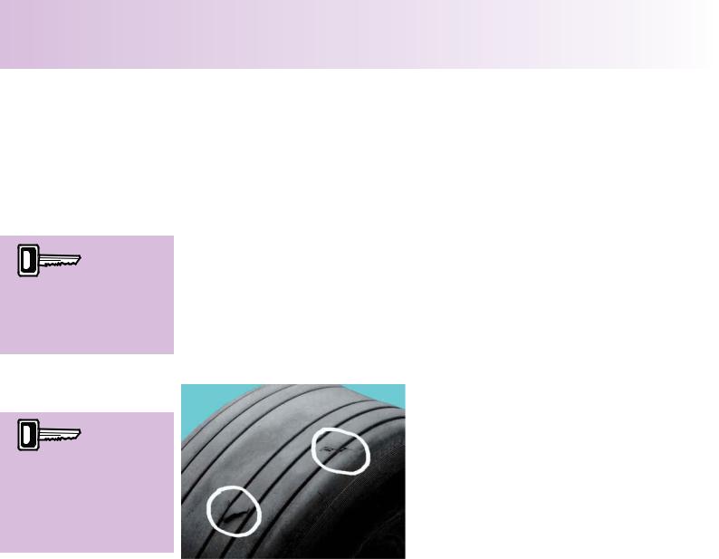
Cr e e p ( Sl i p p a g e ) .
When tyres are first fitted to a wheel they |
|
tend to move slightly around the rim. This |
|
phenomenon is called ‘creep’ and at this |
|
stage it is considered normal. After the tyres |
Figure 2.12. Misaligned Creep Marks. |
settle down, however, this movement should |
|
cease. |
|
Awl vents
prevent pressure
being trapped
between the plies which would cause damage to the tyre when it is exposed to the low atmospheric pressures of high altitude flight.
Protect tyres from excessive heat,
dampness, bright sunlight, contact with oil, fuel and hydraulic fluid. Any hydraulic fluid inadvertently spilt onto a tyre must be wiped off immediately
When tyres are
first fitted to a wheel they
tend to move
slightly around the rim. This phenomenon is called ‘creep’ .
29
Order: 6026
Customer: Oleg Ostapenko E-mail: ostapenko2002@yahoo.com
Customer: Oleg Ostapenko E-mail: ostapenko2002@yahoo.com
CH AP T ER 2 : LANDING G EAR , T Y R ES AND BR AK ES
“Creep marks” are painted
on both the bead of the
tyre and on the flange of the wheel so that movement of the tyre around the wheel can be determined.
In service, the tyre may tend to continue to creep around the wheel. If this creep is excessive on a tyre fitted with an inner tube, it will tear out the inflation valve and cause the tyre to burst. Creep is less of a problem with tubeless tyres, as long as the tyre bead is undamaged and any pressure drop is within limits.
Creep is less likely to occur if the tyre air pressure is correctly maintained. To assist in this, tyre manufacturers specify a rated inflation pressure for each tyre.
Witness marks called ‘creep marks’ are painted both on the bead of the tyre and on the flange of the wheel. When the tyre is first fitted to the wheel, the creep marks will be aligned with each other. However, for a variety of reasons, including heavy landings, harsh braking and low tyre pressures, the tyre will move around the wheel and the creep marks will move in relation to each other.
Movement of the tyre around the wheel must not be such that the creep marks become fully misaligned with each other, as illustrated in Figure 2.12.
Any damage to the tyre
must be carefully examined to check if the fabric of the tyre has been weakened unduly; if there is any doubt about the
serviceability of a tyre, the tyre should be replaced.
T y r e Da m a g e .
Figure 2.13. Cuts in the Tread of a Tyre.
During your pre-flight inspection, tyres must be examined for cuts, bulges, embedded stones, metal or glass, signs of wear, creep, etc.
Cuts in the tyre cover penetrating to the cords render the tyre unserviceable. The cords will be recognisable as pieces of white fibrous material embedded in the rubber of the tyre.
Bulges may indicate a partial failure of the casing. If the fabric is fractured, the tyre must be renewed.
Embedded stones, metal, glass etc. must be removed and the cuts examined by a qualified aircraft technician to ascertain their depth.
The decision whether or not the tyre should be repaired or replaced is governed by the depth of the cut. Any flat spots on the tyre tread, especially those caused by skidding or aquaplaning (see Figure 2.17), must be examined with great care to determine whether the fabric of the tyre has been unduly weakened. If there is any doubt about the serviceability of a tyre, it should be replaced.
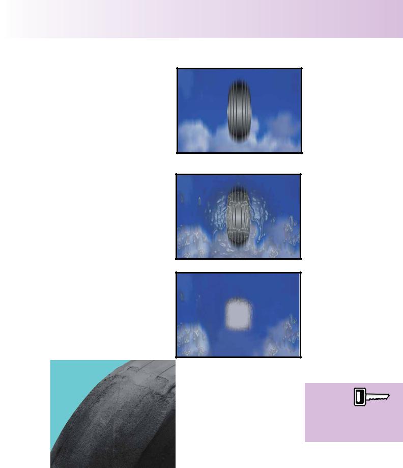
AQUAPLANING.
Aquaplaning is a phenomenon caused by a wedge of water building up under the tread of the tyre and breaking its contact with the ground.
30
ID: 3658
Customer: Oleg Ostapenko E-mail: ostapenko2002@yahoo.com
Customer: Oleg Ostapenko E-mail: ostapenko2002@yahoo.com
CH AP T ER 2 : LANDING G EAR , T Y R ES AN
Figure 2.14 shows a tyre moving slower than aquaplaning speed. It can be seen that there is quite a large footprint still in contact with the ground. In this case the tyre is still capable of gripping the runway.
In Figure 2.15, the wedge of water is in the process of lifting the tyre clear of the runway, although at this stage there is still a small footprint which may supply adequate grip.
Figure 2.14 Satisfactory contact between tyre and surface.
Figure 2.16 shows the tyre footprint reduced to zero, at aquaplaning speed. The wedge of water has lifted the tyre completely clear of the runway. No grip is being obtained by this tyre in this situation.
Figure 2.15 Tyre Footprint Reducing.
Figure 2.16 Tyre Aquaplaning.
Aquaplaning speed, measured in nautical miles per hour, is the speed at which the tyre loses contact with the ground. It can be found by applying the formula:-
AQUAPLANING SPEED = 9 stttP (where P = the tyre pressure in lb/in²) or
AQUAPLANING SPEED = 34 stttP (where P = the tyre pressure in kg/cm2)
Figure 2.17. A Tyre Damaged by Aquaplaning.
Aquaplaning
speed can be calculated,
in knots, by
multiplying the square root of the tyre pressure, in PSI, by nine.
31

Order: 6026
Customer: Oleg Ostapenko E-mail: ostapenko2002@yahoo.com
Customer: Oleg Ostapenko E-mail: ostapenko2002@yahoo.com
CH AP T ER 2 : LANDING G EAR , T Y R ES AND BR AK ES
The amount of heat generated
in stopping even a light aircraft is extremely large.
The bigger the aircraft, the greater the amount of heat generated.
If there is a wheel or brake
fire, the best extinguishant to
use is dry powder.
The possibility of aquaplaning increases as the depth of the tread is reduced; it is, therefore, important that the amount of tread remaining is accurately assessed.
AIRCRAFT WHEEL BRAKES.
In common with most braking systems, aircraft wheel brakes function by using friction between a fixed surface and a moving one to bring an aircraft to rest, converting kinetic energy into heat energy in the process. The amount of heat generated in stopping even a light aircraft is extremely large. The bigger the aircraft, the greater the heat. The problem of dissipating the heat generated by aircraft brakes has been a challenge to aircraft designers and scientists for decades.
Di s c Br a k e s .
Most light aircraft now use hydraulic disc brakes as their means of slowing down or stopping (see Figure 2.18).
These use a series of fixed frictionpads, bearing on, or gripping, a rotating disc, similar to the disc brakes on a car.
The friction-pads are made of an inorganic friction material and the discs are of forged steel with a specially casehardened surface. This surface and interior structure combination causes the plates to explode if doused with a liquid fire extinguishant when they
are red hot. In the event of a wheel
or brake fire, the best extinguishant to Figure 2.18. An Aircraft Disc Brake Assembly. use is dry powder.
Br a k e O p e r a t i o n .
If pressure is applied to the brake pedals or the hand brake lever, hydraulic pressure will build up in the slave cylinder behind the piston. This pressure will cause the piston to move over within the caliper unit, pushing the brake pad against the brake disc (see Figure 2.20).
Figure 2.19 No Brake Pressure Applied. |
Figure 2.20 Brake Pressure Applied. |
32