

ppl_06_e2
.pdfID: 3658
Customer: Oleg Ostapenko E-mail: ostapenko2002@yahoo.com
Customer: Oleg Ostapenko E-mail: ostapenko2002@yahoo.com
CH AP T ER
Figure 3.5 The Two Halves of the Crankcase
Joined Together.
The cylinders are made of alloy steel.
The cylinders resist the pressure of combustion and provide a working surface for the piston rings. If the engine is ‘air cooled’ the cylinders are ‘finned’ to increase the cooling area.
Pistons, (see Figure 3.7) made from light alloy, are fitted within the cylinders. Around each piston are fitted two, or, in some cases, three piston rings.
The piston rings are made from cast iron, which contains a large amount of graphite: a substance which allows
self lubrication between the rings and Figure 3.6 A Finned Cylinder. the cylinder walls when the engine is
first started. The rings ensure that no gases leak from above the piston into the crankcase, which, in a wet sump engine, constitutes a reservoir for the engine oil. For more information on wet and dry sump engines refer to Chapter 5, Lubrication.
The connecting-rod (see Figure 3.8) transmits the forces of combustion to the crankshaft.
Figure 3.7 The Piston, complete with Gudgeon Pin and Piston Rings.
3 : ENG INES G ENER
The cylinders
of an ‘air cooled’
engine are
‘finned’ to increase the cooling area.
Piston rings
are made from cast iron,
which contains
a large amount of graphite, a substance which assists self lubrication when the engine is first started.
43

Order: 6026
Customer: Oleg Ostapenko E-mail: ostapenko2002@yahoo.com
Customer: Oleg Ostapenko E-mail: ostapenko2002@yahoo.com
CH AP T ER 3 : ENG INES G ENER AL
The connecting-rod is made from |
|
‘H’-section high tensile steel, which |
|
combines lightness with the strength |
|
necessary to withstand the compressive |
|
and tensile loads imposed as the piston |
|
changes direction. |
|
The connecting-rod is joined to the |
|
piston by a gudgeon pin (see Figure |
|
3.7) which fits through the ‘small end’ of |
|
the rod. The connecting-rod is joined |
|
to the crankshaft, at the crank pins by |
|
a large circular bearing called the ‘big |
|
end’. |
Figure 3.8 The Connecting Rod. |
|
The crankshaft converts the
linear motion of the piston into
rotary motion.
Each valve is  only required
to open and close once per
working cycle.
The crankshaft converts the linear motion of the piston into rotary motion. It transmits torque, the engine’s turning moment, to the propeller and provides the drive for
accessories.
The journals, which are the main part of the crankshaft, are supported in the
‘main’ bearings within the crankcase.
The crank-pins are offset from the journals by a distance termed the ‘crank throw’. The crank throw determines the piston stroke, and there are two ‘throws’ to one stroke.
Figure 3.10 shows a plan view of the pistons fitted to a crankshaft in a horizontally opposed engine, via the connecting rods. The view shows the two front pistons, those on the left of the picture, both at bottom dead centre, while the two rear pistons, those on the right of the picture, are both at top dead centre.
The cylinder head (see Figure 3.11) is generally made of aluminium alloy and is finned to improve heat dissipation. It seals one end of the cylinder to provide a combustion chamber for the mixture.
The cylinder head accommodates the valves and the sparking plugs and supports the valve rocker arms. The valve rocker arms are operated indirectly by a camshaft (or shafts) (see Figure 3.12) which is a shaft with eccentric lobes machined on it. The camshaft is driven by the crankshaft at half the crankshaft speed.
The camshaft is driven at half crankshaft speed because each valve is required to open and close only once per working cycle, that is, once every two revolutions of the crankshaft.
44

ID: 3658
Customer: Oleg Ostapenko E-mail: ostapenko2002@yahoo.com
Customer: Oleg Ostapenko E-mail: ostapenko2002@yahoo.com
CH AP T ER 3 : ENG INES G ENER
|
The valves are kept concentric to |
|
|
||
|
the valve seats by valve guides. |
|
|
The valve seat is ground to form a |
|
|
gas tight seal with the face of the |
|
|
valve. The valves themselves, both |
|
|
inlet and exhaust, open and close |
|
|
the passages for the induction and |
|
|
scavenging of the gases. |
|
|
The face of each valve is accurately |
|
|
machined to the same angle as the |
|
|
valve seat. The valve and the seat |
|
|
are then ‘lapped’ or ground together |
|
|
with an abrasive paste until a full |
|
Figure 3.11 The Cylinder Head. |
||
contact is obtained. |
The valve springs are manufactured from special spring steel, and they ensure that the valves remain closed except when they are being operated by the rocker assembly.
Figure 3.12 Cutaway of Cylinder Head and Crankshaft.
The springs are of the helical coil type, the usual practice being for two springs to be fitted to each valve, one inside the other.
This provides a safety factor, and also eliminates ‘valve bounce’, a condition created by the fact that each valve spring will have a resonant frequency (with the engine RPM) where it will be ineffective at closing the valve on its own.
Two springs
are fitted to each valve,
one inside
the other. This provides both a safety factor and eliminates ‘valve bounce’.
45
Order: 6026
Customer: Oleg Ostapenko E-mail: ostapenko2002@yahoo.com
Customer: Oleg Ostapenko E-mail: ostapenko2002@yahoo.com
CH AP T ER 3 : ENG INES G ENER AL
The ‘accessory housing’, an example of which is shown in Figure 3.13, is a casing mounted at the rear of the block.
It encloses the drive gear trains for the camshafts, the fuel, oil, pneumatic and vacuum pumps, electric generator, magnetos and tachometer.
Figure 3.13 The Accessory
Housing.
POWER OUTPUT AS A FUNCTION OF RPM.
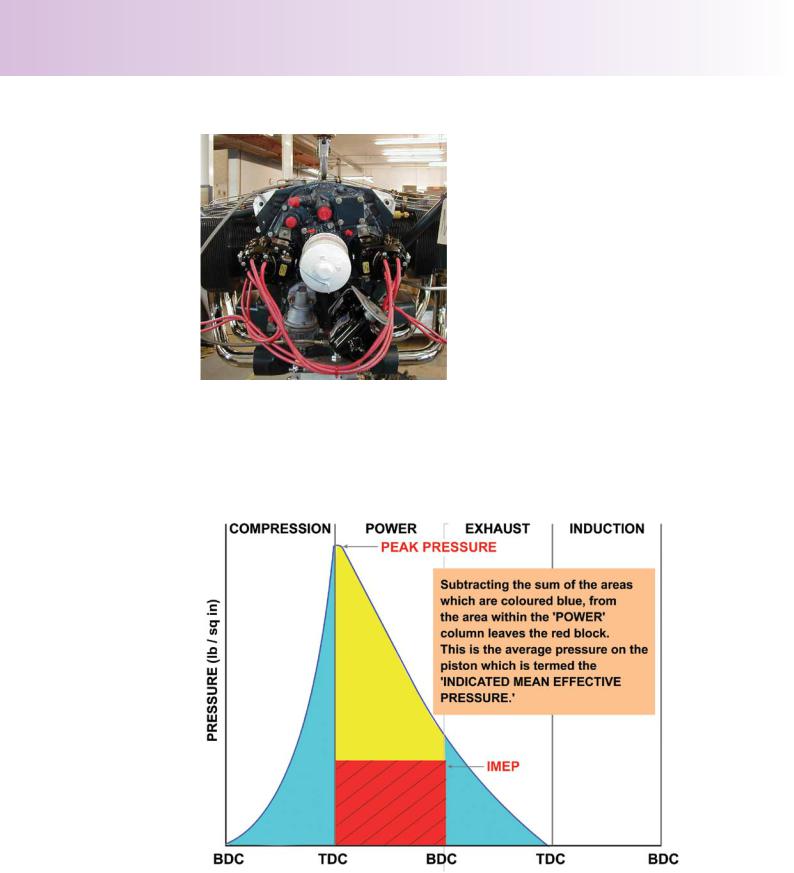
During the four strokes, the changing pressures within the cylinder can be measured and indicated graphically on a device which produces an ‘indicator diagram’. This device is only used during the development stage of an engine.
Figure 3.14 An Indicator Diagram.
Figure 3.14 shows an indicator diagram. The area within the power column represents work done on the piston during the power stroke.
The blue areas represent work done by the piston in compressing the gases and exhausting the cylinder against exhaust back pressure; that is, the pressure which the atmosphere exerts against the outflowing gases.
46

ID: 3658
Customer: Oleg Ostapenko E-mail: ostapenko2002@yahoo.com
Customer: Oleg Ostapenko E-mail: ostapenko2002@yahoo.com
CH AP T ER 3 : ENG INES G ENER
Subtracting the sum of the blue coloured areas from the area within the power column leaves the red block.
The red block is indicative of the ‘average pressure’ during the working cycle. This is termed the ‘Indicated Mean Effective Pressure’ or IMEP.
We can use the Indicated Mean Effective Pressure in the formula, shown below, which allows us to determine the Indicated Horse Power (IHP) of our particular engine.
IHP = P × L × A × N × E 33,000
In the formula, the ‘P’ represents the Indicated Mean Effective Pressure in pounds per square inch. However we are still required to determine several other values.
The ‘L’ represents the length of the stroke in feet, the length of the stroke being the distance the piston moves between Top Dead Centre and Bottom Dead Centre.
‘A’ is cross-sectional the area of the cylinder in square inches.
‘N’ is the number of cylinders that the engine possesses.
‘E’ is the effective working strokes per minute or the RPM of the engine.
33,000 is a constant used to change foot pounds of work per minute into horse power. One Horse Power equals 33,000 foot pounds per minute.
Bearing in mind that, for a given engine, only one function of the formula is variable, that is the RPM of the engine, it is logical to assume that engine power output is directly proportional to RPM: increase the engine speed and the power output increases; decrease the engine speed and the power output falls.
Co m p r e s s i o n R a t i o .
The compression ratio of an engine is the ratio of the total volume enclosed in a cylinder with the piston at Bottom Dead Centre, to the volume remaining at the end of the compression stroke with the piston at Top Dead Centre. This ratio is shown as a formula overleaf.
Figure 3.15 Diagram showing the Total, Swept and Clearance Volumes of a Simple Engine.
Increase
the engine speed and the
power output increases. Decrease the
engine speed and the power output falls.
47

Order: 6026
Customer: Oleg Ostapenko E-mail: ostapenko2002@yahoo.com
Customer: Oleg Ostapenko E-mail: ostapenko2002@yahoo.com
CH AP T ER 3 : ENG INES G ENER AL
The compression
ratio of an engine is the
ratio of the total volume to the clearance volume.
The Total Volume of the engine is the sum of the Swept Volume and the Clearance Volume.
Compression Ratio = |
Total Volume |
|
Clearance Volume |
|
|
An example will help to clarify the term. If the Swept Volume of an engine is 1800 cubic centimetres, and its Clearance Volume is 300 cubic centimetres, what is the compression ratio of the engine?
First we must add the Swept and Clearance Volumes to obtain the Total Volume. So 1800 plus 300 is 2,100.
Then we must divide the Total Volume by the Clearance Volume. 2,100 divided by 300 is 7.
Thus, the compression ratio of the engine is 7 to 1.
48

ID: 3658
Customer: Oleg Ostapenko E-mail: ostapenko2002@yahoo.com
Customer: Oleg Ostapenko E-mail: ostapenko2002@yahoo.com
CH AP T ER 3 : ENG INES G ENER AL Q U E
R e p r e s e n t a t i v e P P L - k n o w l e d g e o f En g i n e s
t y p e q u e s t i o n s t o t e G e n e r a l .
1.In a piston engine aircraft the crankshaft:
a.Converts reciprocating movement into rotary motion
b.Controls the clearance of the valves
c.Converts rotary motion into reciprocating movement
d.Rotates at half the speed of the camshaft
2.During one complete cycle of a four stroke internal combustion engine how many times will each valve open and close?
a.Four times
b.Twice
c.Three times
d.Once
3.If the crankshaft rotates twice in a piston engine, the camshaft rotates:
a.Once, because the camshaft operates at 50% of the engine speed
b.Twice, because the camshaft operates at twice engine speed
c.Four times, because the camshaft operates at twice engine speed
d.Once, because the camshaft operates at twice engine speed
4.In one complete Otto cycle, each piston moves:
a.Up once and down once
b.Up once and down twice
c.Up four times and down four times
d.Up twice and down twice
5.At sea level, the power developed by a four-stroke piston engine:
a.Decreases proportional to RPM.
b.Increases along with RPM
c.Remains constant to RPM
d.Is proportional to the volume of mixture in the cylinder
6.The power output of an internal combustion engine can be increased by:
a.Decreasing the area of the cylinder
b.Decreasing the length of the stroke
c.Increasing the engine RPM
d.Increasing the size of the fuel tank
49

Order: 6026
Customer: Oleg Ostapenko E-mail: ostapenko2002@yahoo.com
Customer: Oleg Ostapenko E-mail: ostapenko2002@yahoo.com
CH AP T ER 3 : ENG INES G ENER AL Q U EST IO NS
7.The correct working cycle of a four stroke engine is:
a.exhaust, power, induction, compression
b.induction, compression, power, exhaust
c.induction, power, compression, exhaust
d.exhaust, induction, power, compression
8.The temperature of the gases within the cylinder of a four stroke engine during the power stroke, after completion of combustion:
a.Decrease
b.Increase
c.Follow Charles’s Law
d.Remain constant
9.Engine compression ratio is the ratio of the:
a.Swept volume to the clearance volume
b.Clearance volume to the swept volume
c.Swept volume to the total volume
d.Total volume to the clearance volume
Question |
1 |
2 |
3 |
4 |
5 |
6 |
7 |
8 |
9 |
Answer |
|
|
|
|
|
|
|
|
|
T h e a n s w e r s t o t h e s e q u e s t i o n s c a n b e f o
50

Customer: Oleg Ostapenko E-mail: ostapenko2002@yahoo.com
CHAPTER 3A
AERO DIESEL ENGINES
51

Order: 6026
Customer: Oleg Ostapenko E-mail: ostapenko2002@yahoo.com
Customer: Oleg Ostapenko E-mail: ostapenko2002@yahoo.com
CH AP T ER 3 A: AER O DIESEL ENG INES
52