

Measurement and Control Basics 3rd Edition (complete book)
.pdfChapter 1 – Introduction to Process Control |
5 |
mined. A device called a controller performs this evaluation. The controller can be a pneumatic, electronic, or mechanical device mounted in a control panel or on the process equipment. It can also be part of a computer control system, in which case the control function is performed by software.
Control
The control element in a control loop is the device that exerts a direct influence on the process or manufacturing sequence. This final control element accepts an input from the controller and transforms it into some proportional operation that is performed on the process. In most cases, this final control element will be a control valve that adjusts the flow of fluid in a process. Devices such as electrical motors, pumps, and dampers are also used as control elements.
Process and Instrumentation Drawings
In the measurement and control field, a standard set of symbols is used to prepare drawings of control systems and processes. The symbols used in these drawings are based on the standard ANSI/ISA-5.1-1984 (R1992)
Instrumentation Symbols and Identification, which was developed by ISA—The Instrumentation, Systems, and Automation Society (ISA) and the American National Standards Institute (ANSI). A typical application for this standard are process and instrumentation diagrams (P&IDs), which show the interconnection of the process equipment and the instrumentation used to control the process. A portion of a typical P&ID is shown in Figure 1-4.
In standard P&IDs, the process flow lines, such as process fluid and steam, are indicated with heavier solid lines than the lines that are used to represent the instrument. The instrument signal lines use special markings to indicate whether the signal is pneumatic, electric, hydraulic, and so on. Table A-1 in appendix A lists the instrument line symbols that are used on P&IDs and other instrumentation and control drawings. In Figure 1-4, two types of instrument signals are used: double cross-hatched lines denote the pneumatic signals to the steam control valve and the process outlet flow control valve, and a dashed line is used for the electrical control lines between various instruments. In process control applications, pneumatic signals are almost always 3 to 15 psig (i.e., pounds per square inch, gauge pressure), and the electric signals are normally 4 to 20 mA (milliamperes) DC (direct current).
A balloon symbol with an enclosed letter and number code is used to represent the instrumentation associated with the process control loop. This

6 Measurement and Control Basics
TIC |
TT |
TE |
100 |
100 |
100 |
|
|
|
Fluid |
TV |
|
|
100 |
FT |
FIC |
|
||
Steam |
101 |
101 |
|
FV |
|
|
FE |
|
|
101 |
101 |
Steam |
|
Heated |
|
|
|
|
|
Fluid |
|
Orifice |
Control |
|
Plate |
Valve |
|
Manual |
|
|
|
|
|
Value |
|
Condensate
Figure 1-4. P&ID: Example
letter and number combination is called an instrument identification or instrument tag number.
The first letter of the tag number is normally chosen so that it indicates the measured variable of the control loop. In the sample P&ID shown in Figure 1-4, T is the first letter in the tag number that is used for the instruments in the temperature control loop. The succeeding letters are used to represent a readout or passive function or an output function, or the letter can be used as a modifier. For example, the balloon in Figure 1-4 marked TE represents a temperature element and that marked TIC is a tempera- ture-indicating controller. The line across the center of the TIC balloon symbol indicates that the controller is mounted on the front of a main control panel. No line indicates a field-mounted instrument, and two lines means that the instrument is mounted in a local or field-mounted panel. Dashed lines indicate that the instrument is mounted inside the panel.
Normally, sequences of threeor four-digit numbers are used to identify each loop. In our process example (Figure 1-4), we used loop numbers 100 and 101. Smaller processes use three-digit loop numbers; larger processes or complex manufacturing plants may require four or more digits to identify all the control loops.
Special marks or graphics are used to represent process equipment and instruments. For example, in our P&ID example in Figure 1-4 two parallel
Chapter 1 – Introduction to Process Control |
7 |
lines represent the orifice plate that is used to detect the discharge flow from the process heater. The two control valves in the figure also use a special symbol. See appendix A for a more detailed discussion of the instrumentation and process symbols that are used on P&IDs.
General Requirements of a Control System
The primary requirement of a control system is that it be reasonably stable. In other words, its speed of response must be fairly fast, and this response must show reasonable damping. A control system must also be able to reduce the system error to zero or to a value near zero.
System Error
The system error is the difference between the value of the controlled variable set point and the value of the process variable maintained by the system. The system error is expressed in equation form by the following:
e(t) = PV(t) – SP(t) |
(1-1) |
where
e(t) |
= system error as a function of time (t) |
PV(t) = the process variable as a function of time
SP(t) = is the set point as a function of time
System Response
The main purpose of a control loop is to maintain some dynamic process variable (pressure, flow, temperature, level, etc.) at a prescribed operating point or set point. System response is the ability of a control loop to recover from a disturbance that causes a change in the controlled process variable.
There are two general types of good response: underdamped (cyclic response) and damped. Figure 1-5 shows an underdamped or cyclic response of a system in which the process variable oscillates around the set point after a process disturbance. The wavy response line shown in the figure represents an acceptable response if the process disturbance or change in set point was large, but it would not be an acceptable response if the change from the set point was small.
Figure 1-6 shows a damped response where the control system is able to bring the process variable back to the operating point with no oscillations.

8 Measurement and Control Basics
PV (Process Variable)
Set Point
Disturbance
 Time
Time
Figure 1-5. Cyclic response to process disturbance
PV (Process Variable)
Set Point |
Disturbance |
Time |
Figure 1-6. Damped response to process disturbance
Control Loop Design Criteria
Many criteria are employed to evaluate the process control’s loop response to an input change. The most common of these include settling time, maximum error, offset error, and error area (Figure 1-7).
PV (Process Variable) |
|
Error Areas |
Offset |
Max. Error |
Error |
Set Point |
|
Settling Time |
|
 Time
Time
Figure 1-7. Evaluation of control loop response
Chapter 1 – Introduction to Process Control |
9 |
When there is a process disturbance or a change in set point, the settling time is defined as the time the process control loop needs to bring the process variable back to within an allowable error. The maximum error is simply the maximum allowable deviation of the dynamic variable. Most control loops have certain inherent linear and nonlinear qualities that prevent the system from returning the process variable to the set point after a system change. This condition is generally called “offset error” and will be discussed later in this chapter. The error area is defined as the area between the response curve and the set point line as shown by the shaded area in Figure 1-7.
These four evaluation criteria are general measures of control loop behavior that are used to determine the adequacy of the loop’s ability to perform some desired function. However, perhaps the best way to gain a clear understanding of process control is to take an intuitive approach.
Intuitive Approach to Process Control Concepts
The practice of process control arose long before the theory or analytical methods underlying it were developed. Processes and controllers were designed using empirical methods that were based on intuition (“feel”) and extensive process experience. Most of the reasoning involved was nonmathematical. This approach was unscientific trial and error, but it was a successful control method.
Consider, for example, an operator looking into an early metal processing furnace to determine whether the product was finished. He or she used flame color, amount of smoke, and process time to make this judgment. From equally direct early methods evolved most of the control concepts and hardware used today. Only later did theories and mathematical techniques emerge to explain how and why the systems responded as they did.
In this section, we will approach the study of control fundamentals in much the same way that control knowledge developed—that is, through a step-by-step procedure starting from manual control and moving to everincreasing automatic control.
Suppose we have a process like that shown in Figure 1-8. A source of feed liquid flows into a tank at a varying rate from somewhere else in a process plant. This liquid must be heated so that it emerges at a desired temperature, Td, as a hot liquid. To accomplish this, hot water, which is available from another part of the plant, flows through heat exchanger coils in the tank. By controlling the flow of hot water, we can obtain the desired tem-

10 Measurement and Control Basics
perature, Td. A further process requirement is that the level of the tank must neither overflow nor fall so low that it exposes the heater coils.
Feed
Hot |
|
|
Water |
|
|
Manual |
Process |
|
Valve |
||
Tank |
||
TI |
||
TT |
||
1 |
1 |
|
Hot |
|
|
Water |
|
LT |
LI |
2 |
2 |
Feed
Manual
Valve
Figure 1-8. Example process – using manual valves
The temperature is measured in the tank, and a temperature transmitter (TT-1) converts the signal into a 4-20 mA direct current (DC) signal to drive a temperature indicator (TI-1) mounted near the hot water inlet valve. Similarly, a level indicator (LI-2) is mounted within the operator's view of the hot feed outlet valve (HV-2).
Suppose a process operator has the task of holding the temperature, T, near the desired temperature, Td, while making sure the tank doesn't overflow or the level get too low. The question is how the operator would cope with this task over a period of time. He or she would manually adjust the hot water inlet valve (HV-1) to maintain the temperature and occasionally adjust the outlet valve (HV-2) to maintain the correct level in the tank.
The operator would face several problems, however. Both indicators would have to be within the operator's view, and the manual valves would have to be close to the operator and easy to adjust.
On/Off Control
To make the operator's work easier, suppose we installed electrically operated solenoid valves in place of the manual valves, as shown in Figure 1-9. We can also install two hand switches (HS-1 and HS-2) so the solenoid

Chapter 1 – Introduction to Process Control |
11 |
valves can be operated from a common location. The valves can assume two states, either fully open (on) or fully closed (off). This type of control is called two-position or on/off control.
HS |
|
Feed |
|
1 |
FV |
|
|
S |
1 |
|
|
Hot |
LT |
LI |
|
Water |
2 |
|
2 |
Solenoid |
Process |
|
|
Valve |
|
|
|
Tank |
|
|
|
TI |
HS |
|
|
TT |
|
||
1 |
1 |
2 |
|
Hot |
|
|
FV |
Water |
|
|
|
|
|
S |
2 |
|
|
|
|
|
|
|
Feed |
|
Solenoid |
|
|
|
Valve |
|
|
Figure 1-9. Sample process: Solenoid valves
Assume for the moment that the level is holding steady and that the main concern is controlling temperature. The operator has been told to keep the temperature of the fluid in the tank at 100°F. He or she compares the reading of the temperature indicator with the selected set point of 100°F. The operator closes the hot water valve when the temperature of the fluid in the tank rises above the set point (Figure 1-10). Because of process dead time and lags the temperature will continue to rise before reversing and moving toward the set point. When the temperature falls below 100°F, the operator opens the hot water valve. Again, dead time and lags in the process create a delay before the temperature begins to rise. As it crosses the set point, the operator again shuts off the hot water, and the cycle repeats.
This cycling is normal for a control system that uses on/off control. This limitation exists because its impossible for the operator to control the process exactly with only two options.
This on/off type of control can be expressed mathematically as follows:
e = PV – SP |
(1-2) |

12 Measurement and Control Basics
Process Variable (PV) |
Temperature Changes |
|
|
100oF |
Set Point (SP) |
Valve Position (V)
Open
Closed 


Figure 1-10. “On/off” temperature control
where
e |
= |
the error |
SP |
= |
the set point |
PV |
= |
the process variable |
In the on/off control mode, the valve is open valve when the error (e) is positive (+), and the valve is closed when e is negative (–).
Proportional Control
When we view the process as a balance between energy in and energy out, it is clear that smoother control would result if a steady flow of hot water were maintained rather than the sudden changes between ON and OFF.
The problem is finding the correct value for the steady flow required for proper control. Obviously, for each rate of feed flow in and out of the tank, some ideal amount of inlet water flow exists that will hold the outlet temperature, T, at 100°F.
This suggests that we should make two modifications to our control mode or strategy. The first is to establish some steady-flow value for the hot water that, at average operating conditions, tends to hold the process variable (temperature) at the desired value or set point (100°F). Once that average flow value has been established for the hot water, increases or decreases of error (e = SP – PV) must be allowed to cause corresponding increases and decreases in water flow from this normal value. This illustrates the concept of proportional control (i.e., initiating a corrective action to a value that is in some proportion to the change in error or deviation of the process variable from set point).

Chapter 1 – Introduction to Process Control |
13 |
Before proportional control can be implemented on our sample process, we must change the solenoid valves to adjustable control valves. Such valves can be positioned to any degree of opening—from fully closed to fully opened—depending on the type of valve actuator mechanism you choose (generally either an electrically or pneumatically operated diaphragm actuator). Our sample process now looks like Figure 1-11, which now shows the use of pneumatically operated control valves (TV-1 and LV-2) and process controllers (TIC-1 and LIC-2). Control valves and controllers in the system make it possible to achieve better control of the process.
IA |
TY |
TY |
|
1 |
1 |
||
|

 Raw Feed TV
1
Hot |
LT |
LIC |
|
Water |
2 |
2 |
|
|
Process |
|
|
TT |
Tank |
LY |
|
IA |
|
||
1 |
2 |
|
|
|
|
||
Water |
|
I/P |
LV |
|
|
||
|
|
|
2 |
Hot Feed
Figure 1-11. Sample process: Proportional control
Proportional control can be described mathematically as follows:
V = Kce + m |
(1-3) |
where
V |
= |
is the control valve position |
Kc |
= |
is the adjustable proportional gain of a typical process |
|
|
controller |
m |
= |
is a constant, which is the position of the control valve |
|
|
when the system error (e) is zero. |
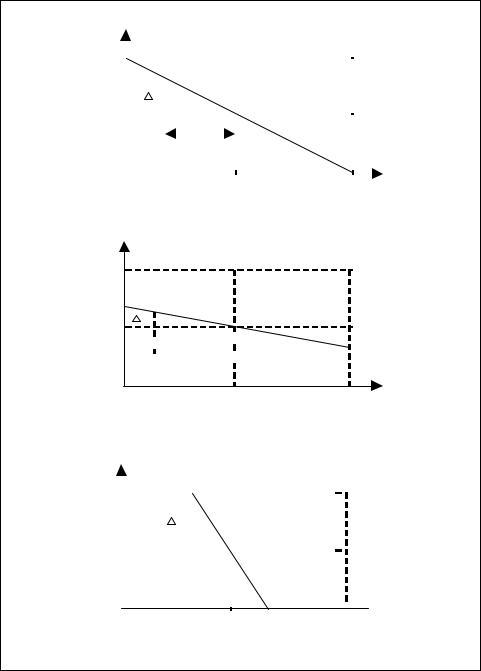
Proportional control can be illustrated by using the three graphs in Figure 1-12 and setting the proportional constant to three different values (i.e., Kc = 1, Kc <1, and Kc >1).
14 Measurement and Control Basics
Valve Position (V) |
|
|
|
|
|
|
|
|
|
|
|
|
|
|
|
|
|
|
|
|
|
|
|
|
|
|
|
|
|
|
|
|
|
|
|
|
|
|
|
|
|
||||||||||||||
|
|
|
|
|
|
|
|
|
|
|
|
|
|
|
|
|
|
|
|
|
|
|
|
|
|
|
|
|
|
|
|
|
|
|
|
|
|
|
|
|
|
|
|
|
|
|
|
|
|
|
|
|
|
|
|
Open |
|
|
|
|
|
|
|
|
|
|
|
|
|
|
|
|
|
|
|
|
|
|
|
|
|
|
|
|
|
|
|
|
|
|
|
|
|
|
|
|
|
|
|
|
|
|
|
|
|
|
|
|
|
|
|
|
|
|
|
|
|
|
|
|
|
|
|
|
|
|
|
|
|
|
|
|
|
|
|
|
|
|
|
|
|
|
|
|
|
|
|
|
|
|
|
|
|
|
|
|
|
|
|
|
|
|
|
|
|
||
|
|
|
|
|
|
|
|
|
|
|
|
|
|
|
|
|
|
|
|
|
|
|
|
|
|
|
|
|
|
|
|
|
|
|
|
|
|
|
|
|
|
|
|
|
|
|
|
|
|
|
|||||
|
|
|
|
|
|
|
|
|
|
|
|
|
|
|
|
|
|
|
|
|
|
|
|
|
|
|
|
|
|
|
|
|
|
|
|
|
|
|
|
|
|
|
|
|
|
|
|
|
|
|
|||||
|
|
|
|
|
|
|
|
|
|
|
|
|
|
|
|
|
|
|
|
|
|
|
|
|
|
|
|
|
|
|
|
|
|
|
|
|
|
|
|
|
|
|
|
|
|
|
|
|
|
|
|||||
|
|
|
|
|
|
|
|
|
|
|
|
|
|
|
|
|
|
|
|
|
|
|
|
|
|
|
|
|
|
|
|
|
|
|
|
|
|
|
|
|
|
|
|
|
|
|
|
|
|
|
|
|
|
|
|
|
|
|
|
|
|
|
|
|
|
|
|
|
|
|
|
|
|
|
|
|
|
|
|
|
|
|
|
|
|
|
|
|
|
|
|
|
|
|
|
|
|
|
|
|
|
|
|
|
|
|
|
|
|
|
|
m |
|
|
|
|
|
V |
|
|
|
|
|
|
|
|
|
|
|
|
|
|
|
|
|
|
|
|
|
|
|
|
|
|
|
|
|
|
|
|
|
|
|
|
|
|
|
|
|
|
|
|
|||||
|
|
|
|
|
|
|
|
|
|
|
|
|
|
|
|
|
|
|
|
|
|
|
|
|
|
|
|
|
|
|
|
|
|
|
|
|
|
|
|
|
|
|
|
|
|
|
|||||||||
|
|
|
|
|
|
|
|
|
|
|
|
|
|
|
|
|
|
|
|
|
|
|
|
|
|
|
|
|
|
|
|
|
|
|
|
|
|
|
|
|
|
|
|
|
|
|
|
|
|||||||
|
|
|
|
|
|
|
|
|
|
|
|
|
|
|
|
|
|
|
|
|
|
|
|
|
|
|
|
|
|
|
|
|
|
|
|
|
|
|
|
|
|
|
|
|
|
|
|
|
|
|
|||||
|
|
|
|
|
|
|
|
|
|
|
|
|
|
|
|
|
|
|
|
|
|
|
|
|
|
|
|
|
|
|
|
|
|
|
|
|
|
|
|
|
|
|
|
|
|
|
|
|
|
|
|
|
|
||
|
|
|
|
|
|
|
|
|
|
|
|
|
|
|
|
|
|
|
|
|
|
|
|
|
|
|
|
|
|
|
|
|
|
|
|
|
|
|
|
|
|
|
|
|
|
|
|
|
|
|
|
|
|
||
|
|
|
|
|
|
|
|
|
|
|
|
|
|
|
|
e |
|
|
|
|
|
|
|
|
|
|
|
|
|
|
|
|
|
|
|
|
|
|
|
|
|
|
|
|
|
|
|
|
|
||||||
|
|
|
|
|
|
|
|
|
|
|
|
|
|
|
|
|
|
|
|
|
|
|
|
|
|
|
|
|
|
|
|
|
|
|
|
|
|
|
|
|
|
|
|
|
|
|
|
|
|
|
|||||
|
|
|
|
|
|
|
|
|
|
|
|
|
|
|
|
|
|
|
|
|
|
|
|
|
|
|
|
|
|
|
|
|
|
|
|
|
|
|
|
|
|
|
|
|
|
||||||||||
|
|
|
|
|
|
|
|
|
|
|
|
|
|
|
|
|
|
|
|
|
|
|
|
|
|
|
|
|
|
|
|
|
|
|
|
|
|
|
|
|
|
|
|
||||||||||||
Close |
|
|
|
|
|
|
|
|
|
|
|
|
|
|
|
error |
|
|
|
|
|
|
|
|
|
|
|
|
|
|
|
|
|
|
|
|
|
|
|
|
|
PV |
|||||||||||||
|
|
|
|
|
|
|
|
|
|
|
|
|
|
|
|
|
|
|
|
|
|
|
|
|
|
|
|
|
|
|
|
|
|
|
|
|
|
|
|
||||||||||||||||
|
|
|
|
|
|
|
|
|
|
|
|
|
|
|
|
|
|
|
|
|
|
|
|
|
|
|
|
|
|
|
|
|
|
|
|
|
|
|
|
||||||||||||||||
|
|
|
|
|
|
|
|
|
|
|
|
|
|
|
|
|
|
|
|
|
|
|
|
|
|
|
|
|
|
|
|
|
|
|
|
|
|
|
|
|
|
|
|
|
|
|
|
|
|
|
|
|
|
||
|
|
|
|
|
|
|
|
|
|
|
|
|
|
|
|
|
|
|
|
|
|
|
|
|
|
|
|
|
|
|
|
|
|
|
|
|
|
|
|
|
|
|
|
|
|
|
|
|
|
|
|
|
|
||
|
|
|
|
|
|
|
|
|
|
|
|
|
|
|
|
|
|
|
|
|
|
|
|
|
|
|
|
|
|
|
|
|
|
|
|
|
|
|
|
|
|
|
|
|
|
|
|
|
|
|
|
||||
|
|
|
|
|
|
|
|
|
|
|
|
|
|
|
|
|
|
|
|
|
|
|
|
|
|
SP |
|
|
|
|
|
|
|
|
|
|
|
|
|
|
|
|
|
|
|
|
|
|
|
|
|||||
0% |
|
|
|
|
|
|
|
|
|
|
|
|
|
|
|
|
|
|
|
|
|
|
100% |
|
|||||||||||||||||||||||||||||||
a) Gain of one, KC = 1
Valve Position (V)
Open
V
 e
e 
 error
error 
Close
0% |
|
|
|
|
|
|
|
|
|
|
|
|
|
|
|
|
|
|
|
|
SP |
|
|
|
|
|
|
|
|
|
|
|
|
|
|
|
|
|
|
|
|||||||
b) Low Gain, KC < 1. |
|
|
|
|
|
|
|
|
|
|
|
|
|
|
|
|
|
|
|
||||||||||||||||||||||||||||
Valve Position (V) |
|
|
|
|
|
|
|
|
|
|
|
|
|
|
|
|
|
|
|
|
|
|
|
|
|
|
|
|
|
|
|
|
|
|
|
||||||||||||
Open |
|
|
|
|
|
|
|
|
|
|
|
|
|
|
|
|
|
|
|
|
|
|
|
|
|
|
|
|
|
|
|
|
|
|
|
|
|
|
|
|
|
|
|
|
|
|
|
|
|
|
|
|
|
|
|
|
|
|
|
|
|
|
|
|
|
|
|
|
|
|
|
|
|
|
|
|
|
|
|
|
|
|
|
|
|
|
|
|
|
|
|
|
|
|
|
m |
|
|
|
|
|
|
|
|
|
|
|
|
V |
|
|
|
|
|
|
|
|
|
|
|
|
|
|
|
|
|
|
|
|
|
|
|
|||||||||||
|
|
|
|
|
|
|
|
|
|
|
|
|
|
|
|
|
|
|
|
|
|
|
|
|
|
|
|
|
|
|
|
|
|
|
|
|
|
|
|
|
|
|
|||||
|
|
|
|
|
|
|
|
|
|
|
|
|
|
|
|
|
|
|
|
|
|
|
|
|
|
|
|
|
|
|
|
|
|
|
|||||||||||||
|
|
|
|
|
|
|
|
|
|
|
|
|
|
|
|
|
|
|
|
|
|
|
|
|
|
|
|
|
|
|
|
|
|
|
|
||||||||||||
|
|
|
|
|
|
|
|
|
|
|
|
|
|
|
|
|
|
|
|
|
|
|
|
|
|
|
|
|
|
|
|
|
|
|
|
|
|
|
|
|
|
|
|
|
|
|
|
Close |
|
|
|
|
|
|
|
|
|
|
|
|
|
|
|
|
|
|
|
e |
|
|
|
|
|
|
|
|
|
|
|
|
|
|
|
|
|
|
|
|
|
||||||
|
|
|
|
|
|
|
|
|
|
|
|
|
|
|
|
|
|
|
|
|
|
|
|
|
|
|
|
|
|
|
|
|
|
|
|
|
|
|
|
|
|
|
|
|
|
|
|
|
|
|
|
|
|
|
|
|
|
|
|
|
|
|
|
|
|
|
|
|
|
|
|
|
|
|
|
|
|
|
|
|
|
|
|
|
|
|
|
|
|
|
|
|
|
|
|
|
|
|
|
|
|
|
|
|
|
|
|
|
|
|
|
|
|
|
|
|
|
|
|
|
|
|
|
|
|
|
|
|
|
|
|
|
|
|
|
|
|
|
|
|
|
|
|
|
|
|
|
|
|
|
|
|
|
|
|
|
|
|
|
|
|
|
|
|
|
|
|
|
|
|
|
|
|
|
|
|
|
|
|
|
|
|
|
|
|
|
|
|
|
|
|
|
|
|
|
|
|
|
|
|
|
|
|
|
|
|
|
|
|
|
|
|
|
|
|
|
|
|
|
|
|
|
|
|
|
|
|
|
|
|
|
|
|
|
|
|
|
|
|
|
|
|
|
|
|
|
|
|
|
|
|
|
|
|
|
|
|
|
|
|
|
|
|
|
|
|
|
|
|
|
|
|
|
|
|
|
|
|
|
|
|
|
|
|
|
|
|
|
|
|
|
|
|
|
|
|
|
|
|
|
|
|
|
|
|
|
|
|
|
|
|
|
|
|
|
|
|
|
|
|
|
|
|
|
|
|
|
|
|
|
|
|
|
|
|
|
|
|
|
|
|
|
|
|
|
|
|
|
|
|
|
|
|
|
|
|
|
|
|
|
|
|
|
|
|
|
|
|
|
|
|
||||||||||||
0% |
|
|
|
|
|
|
|
|
|
|
|
|
|
|
|
|
|
|
|
SP |
|
|
|
|
|
|
|
|
|
|
|
|
|
|
|
|
|
|
|
||||||||
c) High Gain, KC > 1.
PV
100%

 PV 100%
Figure 1-12. Proportional control
As these graphs show, the amount of valve change (∆ V) for a given error can vary substantially. A one-to-one relationship is shown in Figure 1-12(a). In that example, the control valve would move 1 percent of its full travel for a corresponding 1 percent change in error or in a one-to-one