

Measurement and Control Basics 3rd Edition (complete book)
.pdf
266 Measurement and Control Basics
pipe to receivers that are also piezoelectric crystals. The fluid flows through the pipe at a velocity v. The distance between each transmitterreceiver pair is d. The velocity of the sound through the fluid is v, and the path of the sound lies at an angle α from the pipe wall. The velocity of sound from transmitter A to receiver B (increased by the fluid velocity) is vs + v cos α , and its frequency is as follows:
fa |
= |
vs + v cosα |
(9-32) |
|
d |
||||
|
|
|
The velocity of sound from transmitter B to receiver A (reduced by fluid velocity) is given by vs – v cos α, and its frequency is as follows:
fb = |
vs |
− v cosα |
(9-33) |
||
|
d |
||||
|
|
|
|||
or |
|
|
|
||
∆ f= |
2v cosα |
|
(9-34) |
||
d |
|||||
|
|
|
|||
Since α and d are constant, you can obtain the flow velocity by measuring this beat frequency.
Solving Equation 9-34 for flow velocity we obtain the following:
= (∆ f )(d )
v (9-35)
2 cosα
You obtain the volumetric flow rate by multiplying the flow velocity by the cross-sectional area of the pipe.
The beat frequency is measured by using an electronic mixer. The purpose of the mixer is to translate the higher frequencies to a lower frequency level, where it is possible to amplify and select them more efficiently. In general, the design of a mixer is similar to that of a radiofrequency (rf ) amplifier except that the latter includes an oscillator frequency. The combination of two oscillators and a mixer is referred to as a beat-frequency oscillator (bfo). Example 9-10 shows how to calculate fluid velocity for an ultrasonic flowmeter.
Ultrasonic flowmeters are normally installed on the outside of liquid-filled pipes. This is so the measuring element is nonintrusive and will not induce a pressure drop or disturbance into the process stream. Ultrasonic flowmeters generally cost more than standard flow-measuring devices, such as orifice plates or venturi tubes. However, they can be easily

Chapter 9 – Flow Measurement |
267 |
EXAMPLE 9-10
Problem: Given a beat frequency (∆ f) of 100 cps for an ultrasonic flowmeter, the angle (α ) between the transmitters and receivers is 45o and the sound path (d) is 12 in. Calculate the fluid velocity in feet per second.
Solution: Using Equation 9-34 for the velocity based on the beat frequency gives us the following:
= (∆ f )(d )
v
2 cosα
= (100cycles / sec)(1 ft)
v
2 cos 450
v = 70.7 ft / s
attached to the outside of existing pipes without having to shut down the process or use special pipe sections or isolation valves. For that reason, their overall cost compared to conventional flowmeters is generally less than alternative meters in the larger pipe sizes.
Positive-Displacement Flowmeters
Positive-displacement (PD) flowmeters continuously entrap a known quantity of fluid as it passes through the meter. Since both the number of times the fluid is entrapped and the volume of the entrapped fluid are known, you can easily determine the amount of fluid that has passed through the meter. This section discusses the three common types of PD flowmeters encountered in process control: rotary vane, oval gear, and nutating disk.
Rotary-Vane PD Flowmeters
Rotary-vane flowmeters are widely used in liquid processes where accuracy is important. This type of flowmeter converts the entrapment of liquid into a rotational velocity that is proportional to the flow through the device. The forces exerted by the flowing fluid rotate blades in the meter on a center shaft. The blades and inside body of the meter are machined to close tolerances during manufacture since they must form a tight seal with each other over the life of the flowmeter.
268 Measurement and Control Basics
Oval-Gear PD Flowmeters
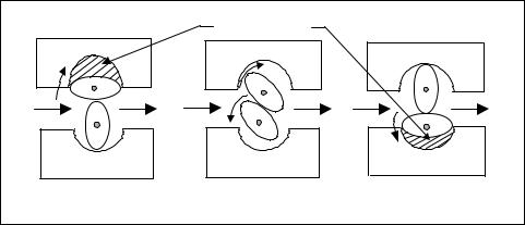
Oval-gear PD flowmeters are generally used on very viscous liquid, which is difficult to measure using other flowmeters. The liquid flow through the meter applies a force on a pair of oval gears, which causes them to rotate.
As Figure 9-14 shows, in position 1 uniform forces are applied equally on the top and bottom of oval gear B, so this gear does not rotate. Rotor A has entrapped a known quantity of liquid between the rotor and the meter body, and there is a balanced force on the top of the gear. However, there is force on the bottom of gear A, which causes it to rotate clockwise (CW). This causes gear B to rotate in a counterclockwise (CCW) direction to position 2.
|
Trapped Liquid |
|
A |
A |
A |
|
||
B |
B |
B |
|
||
|
|
|
Position 1 |
Position 2 |
Position 3 |
Figure 9-14. Oval gear PD meter
In position 2, fluid enters the space between gear B and the meter body, as the fluid that was entrapped between gear A and the body simultaneously leaves the area of entrapment. The higher upstream pressures oppose the lower downstream pressures at the ends of gear A and gear B. This causes both gears to continue to rotate in CW and CCW directions, respectively, to position C.
In position 3, a known amount of fluid has been entrapped between gear B and the meter body. This operation is then repeated, with each revolution of the gears representing the passage of four times the amount of fluid that fills the space between the gear and the meter body. Therefore, the fluid flow is directly proportional to the rotational velocity of the gears.
Nutating-Disk PD Flowmeters
Nutating-disk PD flowmeters are generally used in water service to obtain low-cost flow measurement where high accuracy is not required. The

Chapter 9 – Flow Measurement |
269 |
nutating-disk meter uses a cylindrical measurement chamber, in which a disk is allowed to wobble, or nutate, as fluid flows through the meter, causing the spindle to rotate. This rotation can be used to drive an indicator or transmitter. Since this PD flowmeter entraps a fixed amount of fluid each time the spindle is rotated, the rate of flow is directly proportional to the rotational velocity of the spindle.
Coriolis Mass Flowmeters
The operating principle of Coriolis mass flowmeters is based on the force exerted by the Coriolis acceleration of a fluid. The flowmeter consists of a vibrating tube in which the Coriolis acceleration is created and measured. A typical flow tube is shown in Figure 9-15.
Position detectors
U-tube
 Drive assembly
Inlet Flow |
Outlet Flow |
|
Figure 9-15. Coriolis flow tube
The flow tube is designed and built to have predictable vibration characteristics. A drive assembly connected to the center of the tube causes the tube to twist as shown in Figure 9-15. This vibrates the tube. Position-sens- ing coils on each side of the flow tube sense this twisting. Since the frequency of the vibration of the tube varies with the density of the fluid inside the tube, the computer inside the electronics unit of the Coriolis flowmeter can calculate a density value. Coriolis meters can be used on virtually any liquid or gas that flows at a mass great enough to operate the meter.
Rotameter
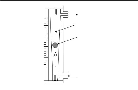
The rotameter is a type of variable-area flowmeter that consists of a tapered metering tube and a float, which is free to move up and down within the tube. The metering tube is mounted vertically, with the small end at the bottom. The fluid to be measured enters at the bottom of the tube, passes upward around the float, and out at the top. Figure 9-16 shows a typical rotameter.
270 Measurement and Control Basics
25 |
Outlet |
|
|
20 |
Glass Tube |
15 |
Metering Float |
|
|
10 |
|
5
0
Inlet
Figure 9-16. Typical rotameter
When there is no flow through a rotameter, the float rests at the bottom of the metering tube, where the maximum diameter of the float is approximately the same as the bore of the tube. When fluid enters the metering tube, the buoyant effect of the fluid lightens the float. However, the float has a greater density than the fluid, and the buoyant effect is not sufficient to raise it.
There is a small annular opening between the float and the tube. The pressure drop across the float increases and raises the float. This increases the area between the float and tube until the upward hydraulic forces acting on it are balanced by its weight, less the buoyant force.
The float moves up and down in the tube in proportion to the fluid flow rate and the annular area between the float and the tube. It reaches a stable position in the tube when the forces are in equilibrium. When the float moves upward toward the larger end of the tapered tube, the annular opening between the tube and the float increases. As the area increases, the pressure differential across the float decreases. The float will assume a position of dynamic equilibrium when the pressure differential across the float plus the buoyancy effect balances the weight of the float. Every float position corresponds to one particular flow rate and no other for a fluid of a given density and viscosity. You take the flow reading from a calibrated scale on the tube.

Chapter 9 – Flow Measurement |
271 |
Glass rotameters are used in many applications, but metal rotameters are used where glass is unsatisfactory. In these cases, you must determine the position of the float indirectly by using either magnetic or electrical techniques. Indirect float position sensors can also provide functions other than direct visual indication. Some rotameters output pneumatic, electronic, or pulse signals.
You can use fluid mechanics theory to derive the following basic equation for liquid flow through a rotameter:
Q = CAa |
ρ F −ρ |
f |
(9-36) |
|
|
||
ρ f |
|
||
|
|
|
where
Q |
= the volumetric flow rate |
||
C |
= a meter flow constant |
||
Aa |
= the annular area between the tube and the float |
||
ρ |
F |
= |
the density of the float |
ρ |
f |
= |
the density of the fluid |
The rotameter is an inexpensive instrument for measuring gas flow. The pressure drop across the meter is essentially constant over the full ten-to- one operating range. The pressure drop is low, generally less than 1 psi.
The position of the float in the metering tube varies in a linear relationship with flow rate. This is true over ranges up to 10:1. Rotameters can directly measure flows as high as 4,000 gal/min. Higher flow rates can be economically handled by using the bypass-type rotameter. Replacing the float with a different-sized float within limits can change the capacity of the rotameter. By using the same housing, but changing both the metering tube and the float, you can achieve a gross change in capacity. These changes can account for both a change in flow rate and a change in fluid density.
The rotameter tends to be self-cleaning. The velocity of the flow past the float and the freedom of the float to move vertically enable the meter to clean itself by eliminating some buildup of foreign material. Liquids that have fibrous materials are an exception, and you should not meter them with rotameters. Generally, particle size, particle type (whether fibrous or particulate), and particulate abrasiveness determine the suitability of the rotameter for a given application. Other factors include the percentage of solids by weight or by volume and the density of the solids.
272 Measurement and Control Basics
EXERCISES
9.1A valve is opened on the bottom of a process storage tank that is filled with liquid to a height of 10 feet. Find the discharge velocity of the liquid just after the outlet valve is opened.
9.2Water at 80°F is pumped through a process pipe with a 2-in. inside
diameter at a flow velocity of 4.0 ft/s. Find the volumetric flow and the mass flow. The density ( ρ ) of water is 62.2 lb/ft3 at 80°F.
9.3An incompressible fluid is flowing in a process pipe that has an inside diameter of 4 in. under a pressure head of 20 in. Calculate the fluid velocity and volume flow rate.
9.4Water at 100 0F is flowing at a rate of 40 gpm through a 2-in. schedule 40 steel pipe. Calculate the Reynolds number and determine if the flow is laminar, transitional, or turbulent. Note that at 100 0F, the density of water is 61.996 lb/ft3, and the viscosity is 0.74 centipose (cP).
9.5Gas that has a density of 0.4 lb/ft3 and viscosity of 0.02 CP is flowing at 1 acfm through a 2-in. schedule 40 pipe. Calculate the Reynolds number and determine if the flow is laminar, transitional, or turbulent.
9.6A liquid is flowing past a restriction in a process pipe with a volumetric flow of 10 ft3 /sec, causing a pressure drop of 2 inH2 O across the restriction. Calculate the volumetric flow if the pressure drop across the restriction increases to 5-inH2 O.
9.7An incompressible fluid is flowing through an orifice plate with a
flow coefficient of 0.9, causing a pressure drop of 10 inH2 O. Calculate the fluid velocity.
9.8Explain the advantages and disadvantages of the three main types of orifice plates.
9.9What is the basic principle used by venturi tubes, flow nozzles, and wedge flow elements to measure flow?
9.10A pitot tube with a coefficient of 0.95 is used to measure the velocity of air in a ventilation duct. The differential pressure head measured by the pitot tube is 1 ft. What is the air velocity?
9.11A digital turbine flowmeter generates 2 pulses per gallon of liquid passing through the meter. Calculate the meter coefficient, and calculate the scaling factor that is necessary to develop an output in which each pulse would represent 10 gallons.
9.12Given a beat frequency (∆ f) of 50 cps for an ultrasonic flowmeter, the angle (α ) between the transmitters and receivers is 45o, and the
Chapter 9 – Flow Measurement |
273 |
sound path (d) is 6 in. Calculate the fluid velocity in feet per second.
BIBLIOGRAPHY
1.Crane Co. Flow of Fluids through Valves, Fittings, and Pipe. Joliet, IL: Crane Co., 1996.
2.Giles, R. V. Theory and Problems of Fluid Mechanics and Hydraulics, Shaum's Outline Series, 2d ed., New York: McGraw-Hill, 1962.
3.Johnson, C. D. Process Control Instrumentation Technology, 2d ed., New York: John Wiley & Sons, 1982.
4.Liptak, B. G., and K. Venczel (ed.). Process Control – Instrument Engineers' Handbook, Radnor, PA: Chilton Book, 1982.
5.Spitzer, D. W. Industrial Flow Measurement, Research Triangle Park, NC: ISA, 1990.