

Mechanical Properties of Ceramics and Composites
.pdf20 |
Chapter 1 |
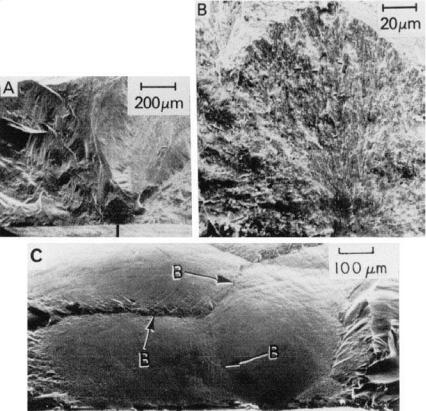
FIGURE 1.8 Example of the knobby, botryoidal surface of many deposited materials, in this case of a Si3N4 coating. (A) and (B) respectively lower and higher magnification SEM photos of deposition surface and cross section.
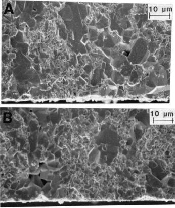
FIGURE 1.9 Example of fine, higher aspect ratio axially aligned grains on room temperature fracture of CVD SiC. (A) Lower magnification SEM showing the fan or sheaf cross section aligned with the axial growth direction (upwards). (B) Higher magnification showing the columnar character of the individual (transgranularly fractured) SiC grains.
Grain and Particle Effects on Ceramic Properties |
21 |
the directional growth they have varying preferred orientations, mainly or exclusively in the axial direction, giving a preferred orientation to the resultant coating or body. This preferred axial orientation within each colony causes it to behave in some fashion as a pseudo larger, oriented grain or particle. Such grainlike behavior commonly includes impacting fracture propagation (Fig. 1.10), and possibly initiation, due to the preferred orientation, as well as possible weaker bonding to adjacent colonies because of orientation-property differences
FIGURE 1.10 Examples of the effects of grain colonies in CVD SiC on fracture at 22°C. (A) and (B) Lower and higher magnification SEMs of fracture initiation (583 MPa) from a colony for stressing normal to the CVD growth direction. (C) Fracture surface from stressing parallel with the growth direction, hence fracture nominally parallel with the plane of deposition. The three major colony boundaries are indicated by B. (After Rice [4], published with the permission of the ASTM.)
22 |
Chapter 1 |
and possible accumulation of impurities or other second phases and pores along colony boundaries. [Pores can more readily form near the base or along the shaft of the colony (bundle of grains) due to slower lateral versus axial growth of the colonies and shadowing of these lower regions due to greater lateral growth of the upper portion of the colony.] Again, the termination of the colonies on the completed deposition surface (i.e. the side opposite from the initiation of the deposition) is the characteristic boytrioidal (i.e. kidneylike) structure. While its occurrence and specifics vary with the material and deposition process, it is a very common aspect of all deposition processes. It is well known in the deposition of graphite, BN, SiC, and Si3N4, since these materials are common candidates for such deposition, and also is common in many other materials, e.g. TiN [26]. In the case of graphite it is common to cause some gas phase nucleation of particles, which on settling to the deposition surface act as nuclei for colonies, so their number is increased and their size reduced, hence mechanical properties improved. The boytrioidal structure and the related growth of grain colonies is also common, but often on a much larger colony scale in a number of mineral deposits, e.g. of important Fe and Cu ores [27].
Turning to other aspects of grain orientation and shape, consider the interrelation of these via particle shape effects in various fabrication methods. Consolidation of powder particles into green bodies results in some preferred particle orientation whenever some of the particles have measurable shape deviations from the equiaxed, i.e. spherical or regular polyhedral. Deviations in terms of particle surface geometry, especially larger flat surfaces, e.g. reflecting crystallographic faces formed in the growth or fracture, can play a role in orientation. However, particle aspect ratio, i.e. of the axial length to the lateral dimensions, is a key parameter. These particle effects, which can be additive, are a necessary condition for orientation, but they become sufficient only in conjunction with varying aspects of different forming methods and their parameters. Thus in pressing operations the aspect ratio of the green part to be formed is a key factor, e.g. lower ratios in die (cold) and hot pressing result in increasing alignment normal to the pressing directions, but random orientation in the plane of pressing. Variations of alignment near the die walls and axial gradients can occur, with the latter often being greater in single versus double acting pressing. Tape casting and lamination typically increase the planer alignment, though the extent and uniformity of this may decrease with increasing tape thickness and decreasing ratio of particle dimensions to tape thickness. This results from shear being an important factor in particle alignment, and shear is highest at the doctor blade surface and grades inward. Similarly, extrusion can result in substantial orientation, which will be greatest at the surface and grade inward, the extent of gradation increasing with the extrudate thickness and decreasing with the ratio of the particle size to the extrudate dimensions. Much more complex orientation effects can occur in injection-molded bodies where
Grain and Particle Effects on Ceramic Properties |
23 |
particle orientation can occur in the stream f material injected into the mold, but then twisted, turned, and deformed in complex ways that depend on the character of the mold shape and its inlet ports.
Grain and particle parameters are also frequently intertwined with other microstructural parameters, especially porosity and impurities. Thus the location, shape, and orientation, and sometimes the size, of pores are related to grain, and especially particle, shape and orientation. For example, as noted earlier, pores in platelet composites commonly remain at the platelet–matrix interface [2], with such pores often being larger and typically somewhat platelet in shape. Similar effects have been indicated in fiber composites [1] and are likely in whisker composites. The relationship of particle and grain parameters being related to impurities results primarily from impurities often being the source of larger grains. Further, such larger grains are often tabular or acicular in shape, which may have implications for orientation and porosity interactions. Some of these effects are illustrated in the next section, and later in the book.
D.Grain and Particle Variations in Ceramic Composites
Grain and particle structures are both important and interrelated in natural and designed composites, and as with nominally single-phase ceramics, they depend substantially on the fabrication method and parameters. Consider first conventional powder-based fabrication methods, where the volume fraction of added particles, whiskers, fibers, or platelets and their sizes relative to the matrix grain size are key parameters. Typically the matrix grains inhibit the growth of the particles and vice versa. The relative degree of inhibition of the added phase on the matrix phase increases as the volume fraction of the added phase increases and its particle size decreases. This mutual inhibition of growth of the matrix and dispersed phases greatly reduces or eliminates the extremes of exaggerated grain growth in either phase and hence the complication of exaggerated grain (or particle) growth noted earlier for nominally single-phase ceramics. Thus just a few volume percent of fine, homogeneously distributed particles of an insoluble second phase can be quite effective in controlling grain growth, e.g. as clearly demonstrated in Al2O3 without MgO but with fine Mo or W [28–30] or ZrO2 particles [31]. As discussed later, this inhibition of matrix grain growth can play an important role in the improvements of strengths of some ceramics and ceramic composites.
A partial exception to the mutual inhibition of growth of grains and particles in ceramic composites can occur in making such composites by in situ reaction of powder ingredients. Thus, Cameron et al. [32] showed that larger grains of various phases, e.g. Al2O3 (Fig. 1.11) and graphite, in such composites, though not as extreme in size as often found in nominally single-phase ceramics, were
24 |
Chapter 1 |
FIGURE 1.11 Example of more extreme microstructural heterogeneity in an Al2O3–27 vol% TiB2 composite made by reactive processing. The larger, primarily or exclusively Al2O3, grains are attributed to melting and resulting “agglomeration” of the Al during its reaction with the TiO2 and B2O3 during hot pressing. (From Ref. 32.)
frequently at fracture origins. At least some of these larger grains were attributed to transient formation of a liquid of a precursor, intermediate, or product phase, thus circumventing normal solid-state mutual inhibition of growth of the phases. The sizes of these grains is commonly large enough so that clusters of them are a factor in the failure of such specimens, but due to inhibiting effects in the composite it is still substantially less extreme than large grains that often occur in nominally single-phase ceramics.
In the above processes, the forming methods and their parameters have a major influence on the orientation of the dispersed phase, as well as some on the matrix grains as in nominally single-phase ceramics. All of this depends sub-
Grain and Particle Effects on Ceramic Properties |
25 |
stantially on the volume fractions, sizes, and especially the shapes of the particles to form the matrix grains and the dispersed phase, and the relation of their shapes to their crystal structure. Use of whiskers, fibers, and platelets for composites are common and has great effects on their orientation in fabricating composites with them. The aspect ratio of the body and the degree of shear resulting from forming operations are key parameters. Thus lower body aspect ratios in die and hot pressing result in increasing alignment normal to the pressing directions, but—random orientation in the plane of pressing. Variations of alignment near the die walls and axial gradients can occur, with the latter often being greater in double versus single-action pressing. Tape casting and lamination typically increase the planar alignment. While characterization of the size, shape, orientation, and spatial distribution of the dispersed phase, as well as of the matrix grain structure, is important, so can be that of the residual pore structure. This arises first since dispersed phases inhibit densification, generally increasingly in the order of particles, whiskers (or short fibers), and platelets. Second, pores are commonly associated with the dispersed phase, the size and character of which impacts the size, shape, and orientation of the pores. Thus platelets in particular commonly have larger laminar or lenticular pores at the platelet–matrix interface.
Processing ceramic composite bodies from the melt is a large and complex subject beyond the scope of this chapter, since it entails many variations and complexities such as varying degrees of liquid solution or immiscibility, and subsolidus phase separation processes (e.g. Refs. 33–35). The latter include varying precipitation within grains and along grain boundaries, which all depend on kinetics, interfacial energies, and their interactions with thermal aspects of the solidification. The latter include the directionality and uniformity of the solidification, the degree of columnar grains formed, and especially their extent of preferred crystallographic orientation. However, beyond the above broad comments, two key points should be noted. First, some of the effects of the multiphase character are used to control the microstructure of the cast bodies, i.e. similar to the effects of multiphase compositions on grain and particle structures in sintered composites.
Second, the interaction of solidification, grain structures, and pore formation should be noted. Pores form in solidifying bodies due to extrinsic and intrinsic effects, the former arise mainly from two sources, as has been recently summarized [1]. An extrinsic source is the release of gases adsorbed on the surfaces of the particles to be melted, e.g. such a pervasive problem that most meltgrown crystals such as sapphire are made from previously melted material. The other extrinsic source is the exsolution of gases upon solidification that were dissolved in the melt. The intrinsic source of porosity in bodies solidified from the melt arises from the typical reduction of volume on solidification. Many ceramics have volume reductions of 5–10%, as is common for most metals, but they
26 |
Chapter 1 |
can be much higher for some ceramic materials, e.g. to > 30%, with alumina compositions commonly having 20% [36].
Introduction of porosity, especially intrinsically generated porosity, can be eliminated by controlled directional solidification wherein the final solidification occurs at a free surface. Such directional solidification typically results in columnar grains of preferred orientation. In bodies at or near eutectic compositions, proper control of the solidification front can result in aligned columnar grains or of single crystals with axially aligned rod or lamellar second phase structures [37–39]. This is a large and extensive topic that is briefly noted here, since such solidified eutectic structures have been of interest for their mechanical behavior (Chap. 8, Sec. V. E, Chap. 9, Sec. III.F, and Chap. II, Sec. IV.E).
Another aspect of melt-processed materials is the crystallization of liquid or amorphous materials, e.g. of glasses. While there are various aspects to this, three are of particular note based on the source and scope of crystallization. The first is homogeneous nucleation throughout the body, which occurs only in a minority of cases. It provides more uniform microstructures, which can be complex at higher levels of crystallization, where crystallites begin to impinge on one another, which occurs sooner as the aspect ratio of the crystallites increases. The second, and more common, case is nucleation from free surfaces, either of a bulk body of the crystallizing glass, or particles of it, e.g. in the latter case prior to or during their consolidation into a dense body. In either case gradients of crystallization commonly result.
Nucleation of a group of crystals from a common point (often a particle of an added nucleation agent) commonly results in the formation of colonies of rod or needle grains radiating from the common nucleation point (Fig. 1.12). The colony grain structure noted in vapor deposited materials in the previous section (Figures 1.7–1.9) is an important subset of a broader occurrence involving the same basic underlying nucleation and growth of grains that is referred to as spherulitic crystallization. Such crystallization extensively occurs from a variety of liquids, including salt solutions, polymers, and melts, e.g. of some fusion cast refractories [34, 35], and especially for glasses (e.g. Refs. 40 and 41). Thus such crystallization occurs in various ceramic and related materials such as cementitious materials and in inorganic, i.e. many silicate-based, glasses [42, 43] of particular pertinence here. There are two aspects of such crystallization that significantly impact the nature of the resultant colony structure, namely the directionality of the nucleation and the subsequent growth of the colony grains and the mutual impingement of growing colonies. Colonies originating from a nucleus small in comparison to the resultant colony size and growing in an isotropic medium may vary from a slightly dog-bone-shaped cross section to a fully circular cross section, depending on parameters that are characteristics primarily of the material and secondarily of the growth conditions. Fully spherical colonies reflect central nucleation and radial growth (Fig. 1.12).

Grain and Particle Effects on Ceramic Properties |
27 |
FIGURE 1.12 Examples of spherulitic crystallization in silicate glasses. (A) Lower magnification of an optical thin section showing an earlier stage of such crystallization in a LiO2–SiO2 glass. (B) Replica electron micrograph of cross section of a more mature spherulite. (C) Fully impinged spherulites in crystallized 3BaO–5SiO2 glass. (From Refs. 42 and 43. Photos courtesy of Dr. S. Freiman of NIST Published with the permission of the Journal of the American Ceramic Society.)
Impingement of growing colonies on one another constrains and changes their resulting shapes, e.g. from spheres to polyhedrons (Fig. 1.12C) similar to grain shapes, e.g. tetrakaidecahedrons. Both directional nucleation, e.g. from larger particles (as in many cementitious materials), or in conjunction with growth fronts (as in the above-discussed vapor deposition processes), and resultant constraint of the growth directons significantly alter the geometry, as shown for CVD materials. However, other complications often occur, e.g. in crystallizing glasses. Important examples are differing separate or overlapping stages of crystallization, whether spherulitic or not, that start, finish, or both the crystallization of the glass. Thus for example prior spherulitic crystallization of 3BaO-5SiO2
28 |
Chapter 1 |
glass is subsequently destroyed by subsequent crystallization into larger lath grains at higher temperatures [43].
Individual grains in such spherulites typically have a preferred orientation in the radial direction but random orientation about their radial axis. Thus one of the characterization challenges that such spherulite structures pose is the contrast of radial orientation in each spherulite versus the global orientation of the body. The latter is typically random, since the orientation within each spherulite is radially symmetric, and there is rarely any coordination of the orientation of different spherulites. However, besides complicating the microstructure, these spherulites can play a role in some key, especially mechanical, properties since they often act as large grains, i.e. as noted earlier for spherulitic clusters of larger grains in sintered bodies (Fig. 1.3) and grain colonies in deposited, e.g. CVD bodies (Figures 1.8–1.10).
IV. GRAIN AND PARTICLE CHARACTERIZATION
AND PARAMETERS
A.Overview
Thorough microstructural characterization to address most, especially all, of the challenges and uncertainties noted in previous sections is a large task that is often beyond the scope and funding allowable for such evaluations. Detailed description and discussion of all, or even the most important, characterization methods and how to make them more effective is a task beyond the scope of this book. The reader is referred to a few references on general characterization (Refs. 44–47, e.g. more current sources as recommended by academic colleagues). The primary problem, however, is that much of the pertinent microstructural characterization in the literature is marginal or inadequate. This arises in part from limitations of many techniques as well as their often being incompletely, inadequately, or inappropriately used, as well as test methods, parameters, or results often being inadequately described. Thus an overview of the process and discussion of some key needs is presented.
The basic approach to the microstructural characterization needed to resolve important issues effectively from both technical and practical standpoints generally consists of two aspects. First and most fundamental is to draw upon information on the material, fabrication-processing, and microstructural trends, preferably from both the literature, e.g. as outlined earlier, and the experience of the investigator and colleagues as a guide for probable needs. The second aspect is a multiple stage, often iterative, characterization of samples, starting with a screening stage of the body being investigated.. Though blanket application of routine evaluations, e.g. basic stereology, can be valuable, selective characterization in a staged fashion based on initial screening and subsequent information is often more effective.
Grain and Particle Effects on Ceramic Properties |
29 |
The initial screening stage should identify the basic microstructural characteristics pertinent to the behavior of concern, as well as indications of the presence or absence of complications such as anisotropies and variations, e.g. gradations and heterogeneities. Such screening should typically entail a range of samples and tests (e.g. as discussed in the next section) aimed at indicating what microstructural factors may be pertinent, variable, and in need of more definition. It should commonly include examination of representative fracture surfaces for both time and cost effectiveness, as well as fracture information, especially for mechanical, but also frequently for nonmechanical, property evaluations. Subsequent characterization stages should be guided by results from previous stages and remaining needs to clarify or confirm the microstructure-material behavior of concern.
The first of three general guides for such evaluations is remembering that the need for, and the effectiveness of, microstructural characterization can depend on the nature of the properties measured and the specifics of the measurements conducted. Thus one microstructural value or technique will not meet all needs as discussed below, e.g. to reflect different effects or extents of variations of the grain size distribution, shapes, and orientations that have differing effects on different properties. Second, qualitative or semiquantitative characterization should always be given in the absence of, as well as often with, detailed quantitative characterization, e.g. illustrative microstructural photos (with scales and comments) can be valuable. This is also true of descriptions of the fabrication, process parameters, and resulting samples. Examples of more detailed, but still incomplete, grain structure descriptions are those of Ting et al. [48] and especially McNamee and Morrell [49]. Third, it is usually valuable to compare different related measurements, e.g. this is often of more value than one more detailed measurement, since all have their limitations.
B.Grain and Particle Size Measurements
Turning to actual measurements of grain and particle size, two aspects of this are detection of the grain and particle structure and then its measurement, which together can entail several stages. Most grain and particle structures are detected by various microscopies, typically in the order of decreasing simplicity and increasing magnification ability and cost: optical (OM), scanning electron (SEM), and transmission electron microscopy (TEM, occasionally still of replicas, but mainly of thin sections). TEM for very fine (submicron) grain or particle structures overlaps with analysis of x-ray and neutron diffraction data to yield grain and particle size information. OM and SEM can be done directly on either polished or fracture surfaces, and OM can also be done on optical thin sections. While both polished and fracture surfaces may require etching to reveal the grain and particle structures, this is primarily so for polished surfaces, which are far