

Ceramic Technology and Processing, King
.pdfForming 153
Figure 6.10: Mix Levelling Tool. A weighed amount of powder is levelled by rotating the plow and slowly raising it to where all of the mix is level.
Referring to Figure 6.9, after the mix is leveled, the top punch is inserted and the die is pressed to part of the final load. Friction between the pressing and the die wall is enough to support the die as the pressure is released. This is called bumping the die and allows entrapped air to escape, and the shims to be removed. Do not put fingers under the die body at this stage as the friction may not be enough to support the die. Since both the top and bottom punches are free to move, the pressing is now double-end pressed to the full pressure. Double-end pressing is far superior to singleend pressing. Pressure gradients in the pressing are much less with pressure applied to both ends, and the part will sinter with less distortion. These gradients were described by Kingery3 and later by Thompson4 in an American Ceramic Society Bulletin. Density gradients are especially severe when the part is long with respect to its diameter. Pressure is held for a few

154 Ceramic Technology and Processing
seconds as the punches will continue to compact the part. A dial micrometer on the press platen will display this movement and is a good guide about when the pressure can be released. The part can now be stripped from the die. The die pressing process is shown in Figure 6.11.
Figure 6.11: Stripping the Die. There are four steps: A. fill the die and insert the top punch press lightly, B. remove the shims and press the part, C. invert the die and place the stripper on top, and D. press down the strip part out of the die.
Forming 155
Part A is the die with the fill ready for pressing. Spacer blocks hold up the die body. B shows the die after lightly pressing and with the spacers removed. Full double-ended pressure is now applied. C shows the die turned over and the stripper placed on the assembly. Strippers can be blocks or a square length of pipe with one side cut out. It must be slightly longer than the bottom punch plus the sample or the sample will be crushed. D shows the part after stripping. To lift the part off cleanly, the top punch has to be a little longer than the die body. During this operation, the die body may suddenly drop. It is not a good idea to place one's fingers under the die body.
There are a number of problems when die pressing. These will be discussed after other die configurations are considered, as the problems are common to all. Refrain from cutting metal until these problems are considered.
Flat Plates
Dies for pressing flat plates are assembled from hardened steel blocks bolted together. Figure 6.12 shows two such illustrations. The design on the right has the advantage that there are only two shapes to the machine. If the cavity is square, then there is only a single shape for all the pieces, saving money in machining costs. Bolt positioning is not optimized in this design for two reasons. First, the bolts are in shear from pressure on adjacent plates. Secondly, the adjacent plates are not pulled up tight on the alignment surfaces. Figure 6.13 depicts a better design. There are two alignment surfaces at each corner A and B. The bolts pull the pieces together against both surfaces that have been precision ground. Each bolt holds the plates with tensile forces. The bolts are at different levels and should be staggered so the die goes together only one way. Two or three tiers of bolts are sufficient for most lab dies depending on the length of the piece being pressed.
Punches for rectangular dies can be a little heavy, and sometimes can be an assembly of a plate that fits the cavity bolted to an extension with a smaller cross section. It is a good idea to hone the sharp corners off the die parts to avoid cuts to one's hands. This can be done quickly with silicon carbide abrasive cloth, available at the local hardware store.

156 Ceramic Technology and Processing
Figure 6.12: Rectangular Die Assembly. There are two ways to design the configuration: orthogonal and series.
Figure 6.13: Die Corner Detail. Each corner has bolts that are in tension in both directions for stability.

Forming 157
Compound Heights
Often, the part will not have a uniform cross section in the vertical dimension. An example is shown in Figure 6.14.
Figure 6.14: Shear Zones in Compound Heights. The center will compact to a lower density than the edges producing cracks and a low density center.
While this example is hypothetical, others just as problematic exist in the real world. There are two problems: length in the center is longer than the length around the sides, and the piece cannot be pressed evenly with more pressure on the shorter side sections. Shear occurs and the piece will likely crack at the location shown. Differences in packing density lead to differences in firing shrinkage. For a shape this difficult, it might be

158 Ceramic Technology and Processing
necessary to mud press, and there is no guarantee that this will work. It may work on a coarsegrained mix but not on a fine-grained mix. Mud pressing uses a mix with enough water and rheology modifiers to make it plastic. In a case like this, the part had to be set on a plaster form to draw off enough water to where it would not slump after stripping from the mold. When the difference between the central length and edge length is much less, there is a chance of pressing the part.
Rings
Rings can be die pressed with tooling as shown in Figure 6.15.
Figure 6.15: Pressing Rings. Rings are fragile. A taper on the corner of the die gradually relieves stresses during stripping.
Forming 159
The central part is floating, or can be held shimmed in place. The problem with pressing rings is that they can be fragile. Spring-back will cause the OD to expand as the ring is stripped from the mold. Note that Figure 6.15 has a relief taper on the bottom of the die. In case there is breakage, the angle of the taper and length should be increased to where the spring-back is compensated. Spring-back on the ID releases the part from the core so that it slips out easily. Fine-grained pressings are more susceptible to fracture than coarse-grained pressings because they have more spring-back. High pressure increases spring-back, and the part becomes even more easily damaged. Backing off on the pressure can help reduce breakage.
Check List, Pressing dies
•Hardened tool steel
•Alignment surfaces
•Die foolproof assembly
•Die strength
•Choice of machine shops
•Polish
•Die design, cylinders, plates, compound heights,
•Rings
Hydraulic presses
In the forgoing discussion, it was assumed that the hydraulic press was simple with only one ram. Of course, presses are available with lots of additional useful functions. A double-ended press, with equal top and bottom rams, and a stripping ram allows the use of fixed dies fastened to the stripping ram. Then, it is not necessary to consider stripping blocks and handling the die. If affordable, one can get fancy control systems where the pressing conditions are automatic.

160 Ceramic Technology and Processing
A 50-ton press is about the right capacity for lab projects. There are some necessary controls including: force on the rams (hydraulic pressure), volumetric flow rate of the hydraulic fluid into the cylinder, dwell time, and stripping rate. Platen positioning is very useful to avoid frequently running the press up and down. Gages dampened with glycerin prevent the needle from jumping around to where it becomes impossible to read accurately. A press this size is preferably a four poster. C-frame presses are tolerable if they are of lower capacity and the additional access is needed from three sides.
Smaller bench presses are useful and available. These are essentially a car jack mounted on a base plate, two posts, and an adjustable top platen. A pressure gage and a hand pump comprise the hydraulic system. These can also have a hydraulic system, and should definitely have a safety shield. Safety shields should protect the operator and others in the lab.
Press platens are not always parallel, especially the type of press just described, as the top platen is frequently moved. One can use a simple alignment fixture to compensate for this misalignment as in Figure 6.16.
Figure 6.16: Die Alignment Fixture. A ball and cone fixture aligns the pressing assembly.
Forming 161
The fixture is placed on the top punch. It is a good idea to make sure that the top platen is well aligned so that the fixture does not squirt out under pressure, although this is not a problem. Higher pressures require larger fixtures, but for most lab work a ball bearing between one half inch and one inch D is about right.
Problems With Die Pressing
Many common things can go wrong. They are:
Lamination
Laminations are cracks that run parallel to the press platens close to the center of the piece. These are usually caused by entrapped air. There are a variety of remedies that usually work. Sometimes, the lamination does not run all the way to the surface, and the piece will have to be broken open to view it. Do not do this on every piece.
Bump the press. After pressing to about 80% of the punch travel, release the pressure and allow the compressed air to escape. For this to work, the pressing has to be permeable, which is a consequence of the green density.
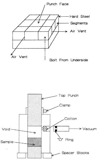
Segmented Punch. When pressing flat plates, the air has to travel a long distance to escape and laminations are common. When the punch face consists of several parts, air can escape along the cracks, as shown in Figure 6.17.
Evacuate the cavity. By removing the air with a vacuum pump, the air entrapment is avoided. The pump can be connected with a side port as shown in Figure 6.18.
162 Ceramic Technology and Processing
Figure 6.17: Segmented Punch Face. Air can vent retarding laminations.
Figure 6.18: Evacuated Die. Removal of air prevents laminations.