

19 - 28 STEERING |
|
Ä |
|
ACUSTAR STANDARD AND TILT STEERING COLUMN
INDEX
|
page |
General Information . . . . . . . . . . . . . . . . . . . . . . |
. 28 |
Ignition Switch Service . . . . . . . . . . . . . . . . . . . . |
. 34 |
GENERAL INFORMATION
WARNING: THE AIR BAG SYSTEM IS A SENSITIVE, COMPLEX ELECTRO-MECHANICAL UNIT. BEFORE ATTEMPTING TO DIAGNOSE, REMOVE OR INSTALL THE AIR BAG SYSTEM COMPONENTS YOU MUST FIRST DISCONNECT AND ISOLATE THE BATTERY NEGATIVE (GROUND) CABLE. FAILURE TO DO SO COULD RESULT IN ACCIDENTAL DEPLOYMENT OF THE AIR BAG AND POSSIBLE PERSONAL INJURY.
THE FASTENERS, SCREWS, AND BOLTS, ORIGINALLY USED FOR THE AIR BAG COMPONENTS, HAVE SPECIAL COATINGS AND ARE SPECIFICALLY DESIGNED FOR THE AIR BAG SYSTEM. THEY MUST NEVER BE REPLACED WITH ANY SUBSTITUTES. ANYTIME A NEW FASTENER IS NEEDED, REPLACE WITH THE CORRECT FASTENERS PROVIDED IN THE SERVICE PACKAGE OR FASTENERS LISTED IN THE PARTS BOOKS.
BEFORE SERVICING A STEERING COLUMN EQUIPPED WITH AN AIR BAG, REFER TO GROUP 8M, ELECTRICAL FOR PROPER AND SAFE SERVICE PROCEDURES.
Safety goggles should be worn at all times when working on steering columns.
The Acustar tilt and standard column (Fig. 1) has been designed to be serviced as an assembly; less wiring, switches, shrouds, steering wheel, etc. Also, most steering column components can be serviced without removing the steering column from the vehicle.
|
page |
Steering Column Component Service . . . . . . . . . |
. 33 |
Steering Column Service Procedures . . . . . . . . . |
. 28 |
CAUTION: Disconnect negative (ground) cable from the battery, before servicing any column component.
CAUTION: Do not attempt to remove the pivot pins to disassemble the tilting mechanism. Damage will occur.
STEERING COLUMN SERVICE PROCEDURES
To service the steering wheel and its components or the air bag, refer to Group 8M, Restraint Systems. Follow all WARNINGS.
To service the switches, refer to the appropriate section of Group 8, Electrical.
To replace the steering column assembly, refer to the steering column removal procedure. For location of components referred to in the procedure see (Fig. 1).
WARNING: BEFORE BEGINNING ANY AIR BAG SYSTEM COMPONENT INSTALLATION OR REMOVAL PROCEDURES. REMOVE AND ISOLATE THE NEGATIVE (-) BATTERY CABLE (GROUND) FROM THE VEHICLE BATTERY. THIS IS THE ONLY SURE WAY TO DISABLE THE AIR BAG SYSTEM. FAILURE TO DO THIS COULD RESULT IN ACCIDENTAL AIR BAG DEPLOYMENT AND POSSIBLE PERSONAL INJURY.

Ä |
|
STEERING 19 - 29 |
|
Fig. 1 Acustar Standard and Tilt Steering Column
19 - 30 STEERING
STEERING COLUMN REMOVAL
(1)Make sure the front wheels of the vehicle are in the straight ahead position.
(2)Disconnect the negative (ground) cable from the battery and isolate cable.
(3)For vehicles equipped with a column shift. Disconnect the transmission shift cable from the steering column by prying it out of the grommet in the shift lever (Fig. 2).
Fig. 2 Shift Cable Removal From Grommet
(4) Remove the steering wheel center pad. Disconnect electrical components such as horn lead, air bag lead and speed control switch lead (if equipped) from center pad (Fig. 3).
Fig. 3 Horn Pad Removal (Typical)
(5)Remove the steering wheel retaining nut from the steering column shaft. Remove steering wheel from shaft using Puller, Special Tool C-3428-B (Fig. 4). Do not bump or hammer on steering column shaft to remove wheel.
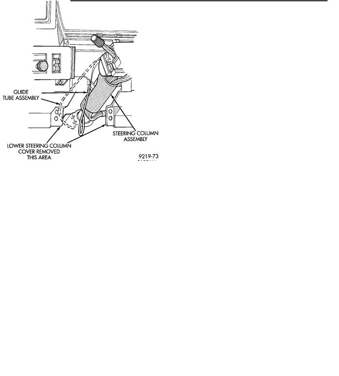
(6)Remove the lower steering column cover (Fig.
5).
(7)Remove the retaining pin in the upper to lower steering coupler retaining bolt (Fig. 6).
Ä
Fig. 4 Removing Steering Wheel (Typical)
Fig. 5 Steering Column Cover Removed
(8)Remove the upper to lower steering coupler retaining nut and pinch bolt (Fig. 6). Remove the upper steering coupler from the lower steering coupler shaft.
(9)Place the gear shift lever in either the neutral or park position.
(10)Remove the PRNDL indicator actuation cable from the steering column actuating arm (Fig. 7).
Ä |
|
STEERING 19 - 31 |
|
Fig. 6 Steering Column Coupler Remove and Install
Fig. 7 PRNDL Cable Removal
(11) Release the lock bar on the column insert. Squeeze the legs of the column insert together and remove insert from steering column assembly (Fig. 7).
(12)Secure the insert and actuation cable out of the way.
(13)Remove tilt lever (if equipped) from steering column.
(14)Remove the upper and lower lock housing shrouds (Fig. 1) from the steering column assembly. Remove the lower fixed shroud from the steering column assembly. The shroud fasteners are Torxhead screws.
(15)Remove the wiring harness connector to the turn signal/multi-function switch using a 7mm socket as shown in (Fig. 8).
Fig. 8 Multi-function Switch Wiring Harness Con-
nector
(16) Remove the electrical connections from the Key-in Switch & Halo Light, Main Ignition Switch, Horn connection or Clock Spring (Speed Control Equipped) (Fig. 9).
Fig. 9 Steering Column Wiring
(17)Loosen the upper steering column support bracket nuts (Fig. 10) to allow some slack. This will aid in removal of the upper fixed shroud.
(18)Remove the upper fixed shroud (Fig. 1) from the steering column assembly. Remove the wiring