


Ä
(19) Transfer the required parts from the removed power steering pump, to the replacement power steering pump.
INSTALL
(1)Install power steering pump back in vehicle, laying it on the steering gear. Do not mount it to the power steering pump bracket.
(2)Install alternator back on the lower alternator bracket and install bolt and nut (Fig. 17). Do not tighten bolt at this time.
(3)Install the alternator bracket back on engine and intake manifold. Loosely install the 4 alternator bracket to engine attaching bolts (Fig. 17). Be sure the SPACER (Fig. 16) is installed between the engine mounting strut and the alternator bracket.
(4)Temporarily install the serpentine belt tensioner bolt through both alternator brackets. This will align all alternator bracket mounting holes (Fig. 13).
Then torque the 4 alternator bracket to engine and intake manifold mounting bolts to 54 NIm (40 ft. lbs.). Then remove the serpentine belt tensioner from bracket. It will be installed on the bracket in a later step.
(5)Tighten the bolt holding the engine bracket as-
sembly to the engine support assembly (Fig. 16) to 150 NIm (110 ft. lbs.).
(6)Attach the engine wiring harness routing clip to the alternator bracket.
(7)Install the alternator to alternator bracket attaching bolt (Fig. 16). Torque bolt to 54 NIm (40 ft.
lbs.). Tighten the lower alternator pivot bolt to 54 NIm (40 ft. lbs.).
(8)Install the power steering pump fluid reservoir and tube/hose assembly onto the power steering pump bracket and alternator bracket (Fig. 15). Torque
the 2 bolts holding the reservoir to the alternator bracket to 5 NIm (45 in. lbs.). Torque the 1 bolt
holding the tube/hose assembly to the power steering pump bracket to 12 NIm (105 in. lbs.).
(9)Raise vehicle See Hoisting, Group 0.
(10)Install the strut assembly power steering/alternator bracket to engine (Fig. 14). Torque
the nut and bolt holding the strut assembly to bracket and the intake manifold stud to 54 NIm (40 ft. lbs).
(11)Install the serpentine drive belt tensioner onto the power steering/alternator bracket (Fig. 13). In-
stall the tensioner to bracket retaining nut and torque to 54 NIm (40 ft. lbs.).
(12)Install the power steering pump on bracket, by aligning the 3 mounting holes in pump with mounting holes in bracket (Fig. 12). Install the 3 power
steering pump to bracket mounting bolts. Torque power steering pump mounting bolts to 54 NIm (40 ft. lbs.).
STEERING 19 - 17
(13)Install the support strut, engine block to power steering pump on pump stud (Fig. 12). Install the nut
and bolt holding the strut to the power steering pump and engine block and torque to 54 NIm (40 ft. lbs.).
(14)Install the power steering fluid pressure line onto the output fitting of the power steering pump
(Fig. 10). Torque the pressure line pump fitting nut to 31 NIm (275 in. lbs.). Before connecting the pressure line to power steering pump inspect the O-ring on the pressure line for damage.
(15)Install the power steering fluid, low pressure return hose on the power steering pump low pressure fitting (Fig. 10). Then install the hose from the remote reservoir onto the power steering pump (Fig.
11).Be sure all hose clamps are properly reinstalled.
(16)Install right front tire and wheel on vehicle. Install the wheel stud nuts and torque to 129 NIm (95 ft. lbs.).
(17)Lower vehicle.
(18)Install the serpentine drive belt. Refer to (Fig.
9)for correct serpentine belt routing. See Cooling, Group 7 for detailed installation procedure.
CAUTION: Do not use automatic transmission fluid in power steering system. Only use MoparT, Power
Steering Fluid, or equivalent.
(19)Fill power steering pump reservoir to correct fluid level.
(20)Connect the negative battery cable on the negative battery post.
(21)Start engine and turn steering wheel several times from stop to stop to bleed air from fluid in system. Stop engine, check fluid level, and inspect system for leaks. See Checking Fluid Level.
TURBO III
REMOVE
(1)Disconnect the battery (-) negative cable from the battery and isolate cable.
(2)Raise vehicle See Hoisting, Group 0. Put oil drain pan under vehicle to catch power steering fluid.
(3)Remove the right front underhood splash shield for access to the serpentine belt tensioner.
(4)Release the tension on the serpentine drive belt tensioner and remove drive belt from power steering pump pulley (Fig. 18). Drive belt does not have to be fully removed from engine.
(5)Remove the power steering fluid return hose at the steering gear metal tube (Fig. 4). Let power steering fluid drain from the hose and power steering pump into drain pan.
(6)Remove the high pressure fluid line banjo bolt fitting (Fig. 4) from the power steering pump. Re-
19 - 18 STEERING |
|
Ä |
|
Fig. 18 Turbo III Accessory Drive Belt Routing
move high pressure power steering fluid line (Fig. 4) from the power steering pump.
(7) Remove the lower power steering pump to bracket mounting nut and fluid hose routing clip. Remove the 2 bolts and the stud attaching the power steering pump to its mounting bracket (Fig. 19).
Fig. 19 Power Steering Pump Mounting
(8)Lower vehicle.
(9)Remove the wiring harness electrical connector from the H-valve on the air conditioning fluid lines.
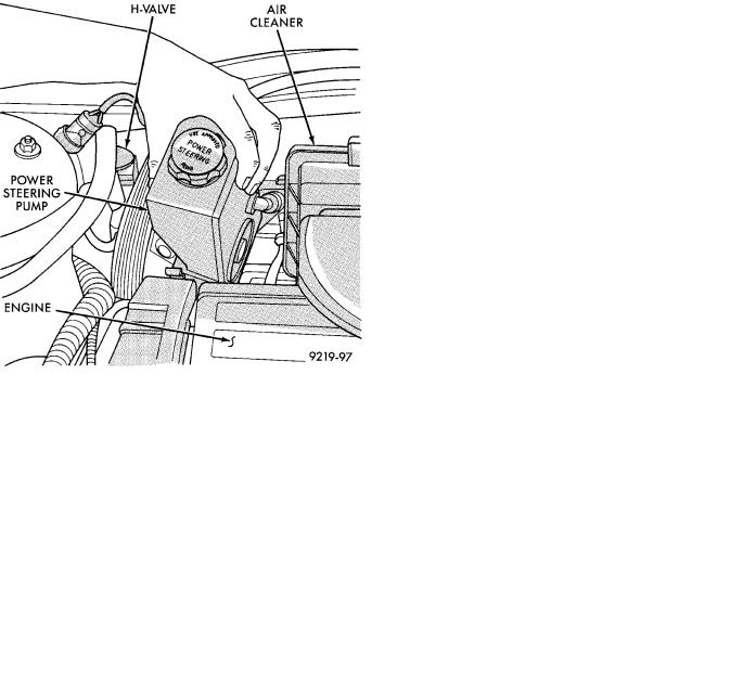
(10)Remove the power steering pump from the vehicle out through the area between the cylinder head and the dash panel (Fig. 20).
(11)Transfer the required components from the failed power steering pump to the replacement power steering pump. See the appropriate area of this service manual section for the component replacement procedures.
Fig. 20 Power Steering Pump Removal From Vehicle
INSTALL
(1)Install the power steering pump back into the vehicle in the reverse order of removal, between cylinder head and dash panel (Fig. 20).
(2)Install the wiring harness connector back on the H-valve located on the air conditioning fluid lines (Fig. 20).
(3)Raise vehicle See Hoisting, Group 0.
(4)Install the power steering pump on its mounting bracket, and the hose locator bracket. Install the bolt/stud and 2 bolts attaching the power steering pump to its mounting bracket, and the bolts attaching
the hose locator bracket (Fig. 19). Torque all fasteners to 31 NIm (280 in. lbs.).
(5)Install the power steering fluid pressure hose, banjo bolt and seal washer onto power steering pump (Fig. 4). Pressure hose is to be installed so it is routed
to the left of the hose locator bracket (Fig. 19). Torque the banjo bolt to 31 NIm (275 in. lbs.). Inspect the
O-rings on the banjo bolt to ensure they are not damaged and located correctly.
(6)Install the low pressure fluid return hose from the power steering pump back on the steel tube on the steering gear (Fig. 4). Install hose clamp, be sure the hose clamp is installed past the retaining bead the steel tube. Install the hose routing clip on the power steering pump bolt/stud, install clip retaining nut and tighten.