

Ä |
|
STEERING 19 - 11 |
|
Fig. 3 Power Steering Hose Routing 3.3 & 3.8l
Fig. 4 Power Steering Hose Routing Turbo III
INSTALLATION
(1)Using a lint free towel, wipe clean the open power steering hose ends, power steering pump and steering gear ports.
(2)Install new O-rings and/or washer seals on the
ends of the power steering hoses. Lubricate O-rings or washer seals using clean power steering fluid.
(3) Attach power steering hose to the proper connections at the power steering pump and steering gear. Route hoses smoothly in their correct position avoiding tight bends or kinking. Install the power steering hose to crossmember routing bracket. Hoses
must remain away from the exhaust system. Do not bend tube ends.
(4)Tighten all fasteners shown for specific applications shown in (Fig. 1 to 4) to their correct torques listed below:
²Pump End Banjo Bolt Ð 34 NIm (25 ft. lbs.)
²Pump End Tube Nut Ð 34 NIm (25 ft. lbs.)
²Gear End Tube Nuts (2) Ð 34 NIm (25 ft. lbs.)
²Crossmember Bracket Bolt Ð 23 NIm (17 ft. lbs.)
²Pump Bracket Nut Ð 40 NIm (30 ft. lbs.)
²Gear Bracket Bolt Ð 68 NIm (50 ft. lbs.)
(5)When used, protective sponge sleeves must be properly positioned on power steering hoses. This is to prevent hose contact with other components.
(6)After hose is installed, check for leaks. (See Pump Installation).
POWER STEERING PUMP REMOVAL
WARNING: POWER STEERING OIL, ENGINE COMPONENTS AND THE EXHAUST SYSTEM MAY BE EXTREMELY HOT IF ENGINE HAS BEEN RUNNING. DO NOT START ENGINE WITH ANY LOOSE OR DISCONNECTED HOSES. DO NOT ALLOW HOSES TO TOUCH HOT EXHAUST MANIFOLD OR CATALYST.
2.2 & 2.5 LITER
REMOVE
(1)REMOVE THE (-) NEGATIVE BATTERY CABLE FROM THE BATTERY AND ISOLATE CABLE.
(2)Loosen power steering pump adjustment bolt and rotate the pump forward in bracket. Remove the power steering pump drive belt from pump (Fig. 1). It is not necessary to remove the power steering pump drive belt from engine.
Fig. 1 Power Steering Pump Drive Belt Removal
19 - 12 STEERING |
|
Ä |
|
(3) Raise vehicle See Hoisting, Group 0. Put oil drain pan under vehicle to catch power steering fluid. Remove hose clamp and low pressure fluid hose from power steering pump (Fig. 2).
Fig. 2 Power Steering Fluid Hoses
(4)Remove the power steering, fluid pressure line (Fig. 2) from the power steering pump. Drain excess power steering fluid from line.
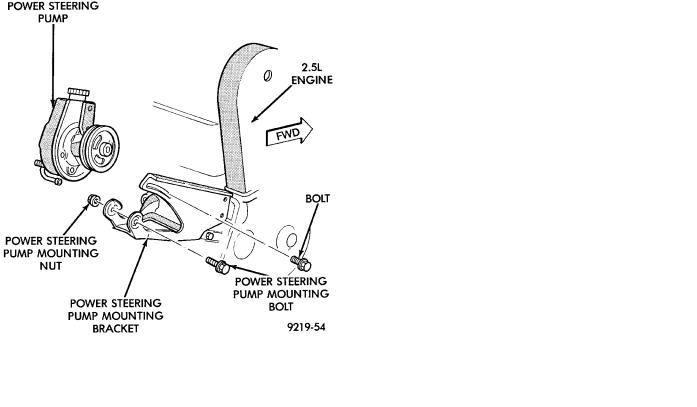
(5)Loosen but do not remove, nut holding the back of the power steering pump to its mounting bracket (Fig. 3). Then remove bolt attaching the pulley side of the power steering pump to the mounting bracket (Fig. 3).
(6)Lower Vehicle. Remove bolt retaining the power steering pump in adjusting slot of the power steering pump mounting bracket (Fig. 3).
(7)Remove power steering pump from vehicle. Pump is removable from the top of the vehicle. Lift power steering pump out of mounting bracket, rotate and lift it out between the engine and dash panel.
(8)Transfer the required parts from the removed power steering pump, to the replacement power steering pump.
INSTALL
(1)Install power steering pump back in vehicle in the reverse order of removal.
(2)Install power steering pump back on mounting bracket. Be sure stud on back of power steering pump is in slotted hole in bracket. Install bolt attaching power steering pump to adjusting slot in bracket (Fig. 3). Do not tighten nut or bolt.
(3)Raise vehicle See Hoisting, Group 0.
Fig. 3 Power Steering Pump Remove And Install
(4)Install the bolt attaching the pulley side of the power steering pump to the mounting bracket (Fig. 3). Do not fully tighten the bolts.
(5)Install the power steering fluid pressure line onto the output fitting of the power steering pump
(Fig. 2). Torque the pressure line pump fitting nut to 31 NIm (275 in. lbs.). Before connecting the pressure line to power steering pump inspect the O-ring on the pressure line for damage.
(6)Install the power steering fluid, low pressure return hose on the power steering pump low pressure fitting (Fig. 2). Install hose clamp on low pressure return hose. Be sure the clamp is installed on hose past upset bead on power steering pump tube.
(7)Lower vehicle.
(8)Install the power steering pump drive belt on pump pulley. Using the power steering pump adjusting bracket (Fig. 1), rotate pump in bracket to obtain correct belt tension. Tighten bolt at power steering
pump mounting bracket adjusting slot (Fig. 1) to 54 NIm (40 ft. lbs.). Torque the power steering pump to
mounting bracket pivot, nut and bolt (Fig. 1) to 54 NIm (40 ft. lbs.).
CAUTION: Do not use automatic transmission fluid in power steering system. Only use MoparT, Power
Steering Fluid, or equivalent.
(9)Fill the power steering pump reservoir to correct fluid level.
(10)Connect the negative battery cable back on the negative battery post.
(11)Start engine and turn steering wheel several times from stop to stop to bleed air from fluid in sys-

Ä |
|
STEERING 19 - 13 |
|
tem. Stop engine, check fluid level, and inspect system for leaks. See Checking Fluid Level.
3.0 LITER
REMOVE
(1)REMOVE THE (-) NEGATIVE BATTERY CABLE FROM THE BATTERY AND ISOLATE CABLE.
(2)Remove the serpentine accessory drive belt from engine (Fig. 4). See Cooling, Group 7 for detailed removal procedure.
Fig. 4 3.0l Serpentine Drive Belt Routing
(3)Remove the hose clamp and bolt mounting the power steering pump filler tube and dipstick assembly (Fig. 5) to power steering pump and alternator bracket. Remove filler tube and dipstick assembly from power steering pump.
(4)Raise vehicle See Hoisting, Group 0.
(5)Remove the 2 nut, bolt and spring assemblies attaching the exhaust pipe to exhaust manifold. Remove exhaust pipe from exhaust manifold and move to left side of vehicle. This is required for clearance to remove power steering pump from vehicle.
(6)Put oil drain pan under vehicle to catch power steering fluid. Remove hose clamp and low pressure fluid hose, from power steering gear fluid tube (Fig. 6). Allow excess power steering fluid to drain from power steering pump and hose.
(7)Loosen the high pressure power steering fluid line fitting at the power steering pump (Fig. 6). Then remove high pressure power steering fluid line from power steering pump.
(8)Remove nut holding the power steering pump rear support bracket to pump (Fig. 7). Then remove the 2 bolts (Fig. 7) mounting the power steering pump support bracket to engine and remove bracket from vehicle.
(9)Remove the 2 bolts that mount the front of the power steering pump to the mounting plate (Fig. 8).
Fig. 5 Power Steering Pump Filler Tube/Dipstick As-
sembly
Fig. 6 Power Steering Hose Remove/Replace
Access to the mounting bolts is through the holes in power steering pump pulley using a deep well socket.
(10)Remove the power steering pump and pulley assembly from vehicle. Remove pump assembly from vehicle in area between floor pan and front suspension crossmember. Pump will fit through area of exhaust pipe tunnel in floor pan.
(11)Transfer Required parts to the new power steering pump assembly before installing in vehicle.

19 - 14 STEERING |
|
Ä |
|
Fig. 7 Power Steering Support Bracket
Fig. 8 Power Steering Pump Mounting 3.0L
INSTALL
(1)Install the power steering pump assembly back in vehicle in reverse order of removal.
(2)Hold power steering pump against mounting plate. Align power steering pump mounting holes with mounting holes in plate and install bolts (Fig. 8).
Torque the 2 power steering pump to mounting plate bolts to 54 NIm (40 ft. lbs.).
(3)Install the rear power steering pump to engine block support bracket, onto the stud on back of power steering pump (Fig. 7). Then install the 2 bolts mounting the support bracket to the engine block.
Torque the 2 support bracket to engine block mounting bolts to 54 NIm (40 ft. lbs.).
(4)Install the nut on stud of power steering pump
attaching pump to rear support bracket (Fig. 7). Torque nut to 54 NIm (40 ft. lbs.)
(5)Install the high pressure power steering fluid line on the power steering pump outlet fitting (Fig. 6).
Torque the high pressure fluid line to power steering pump fitting to 31 NIm (275 in. lbs.).
(6)Install the low pressure power steering fluid hose onto the power steering gear fluid tube (Fig. 6). Install hose clamp on hose. Be sure hose clamp is installed beyond upset bead on tube.
(7)Install the exhaust pipe back on the exhaust
manifold. Install the nut, bolt and spring assemblies and torque bolts to 28 NIm (250 in. lbs.).
(8)Lower vehicle.
(9)Install the power steering pump filler tube and dip stick assembly on the neck of the power steering pump (Fig. 5). Install the bolt (Fig. 5) attaching the
filler tube/dip stick assembly to the alternator bracket. Torque the bolt to 11 NIm (100 in. lbs.).
(10)Position the hose clamp on the filler tube assembly rubber boot and adequately tighten hose clamp.
(11)Install the serpentine accessory drive belt on engine (Fig. 4). See Cooling, Group 7 for detailed installation procedure.
CAUTION: Do not use automatic transmission fluid in power steering system. Only use MoparT, Power
Steering Fluid, or equivalent.
(12)Fill power steering pump reservoir to correct fluid level.
(13)Connect the negative battery cable back on the negative battery post.
(14)Start engine and turn steering wheel several times from stop to stop to bleed air from fluid in system. Stop engine, check fluid level, and inspect system for leaks. See Checking Fluid Level.
3.3& 3.8 LITER
REMOVE
(1)Remove the (-) negative battery cable from the battery and isolate cable.
(2)Remove the serpentine accessory drive belt from engine (Fig. 9). See Cooling, Group 7 for detailed removal procedure.
(3)Raise vehicle See Hoisting, Group 0. Put oil drain pan under vehicle to catch power steering fluid. Remove hose clamp and low pressure fluid hose from power steering pump (Fig. 10).
(4)Remove hose clamp and hose to the power steering pump, from the remote fluid reservoir (Fig. 11). Drain off excess power steering fluid from hoses.
(5)Remove the power steering, fluid pressure line (Fig. 10) from the power steering pump. Drain excess power steering fluid from tube.
(6)Remove right front wheel and tire from vehicle. This will aid in access to the power steering pump mounting bolts.
(7)Remove the 3 bolts holding the power steering pump to the alternator, power steering and belt tensioner mounting bracket (Fig. 12).

Ä |
|
STEERING 19 - 15 |
|
Fig. 9 Serpentine Drive Belt Routing
Fig. 10 Power Steering Hose Routing 3.3 & 3.8L
(8)Remove nut and bolt holding the engine block, to power steering pump support strut. Remove strut from engine and power steering pump (Fig. 12). Lay the power steering pump assembly down on top of the steering gear. It will be removed later from the top.
(9)Remove nut which holds serpentine drive belt tensioner to its mounting bracket (Fig. 13). Remove tensioner assembly from bracket.
(10)Remove nut and bolt attaching the alternator/power steering pump bracket, support strut (Fig. 14).
Fig. 11 Power Steering Remote Fluid Reservoir And
Tube
Fig. 12 Power Steering Pump Mounting 3.3L
(11)Lower vehicle.
(12)Remove the 2 bolts holding the power steering fluid reservoir to the alternator bracket. Remove the bolt attaching the tube/hose assembly to the power steering pump bracket (Fig. 15). Then remove the fluid reservoir and tube/hose as an assembly from vehicle.
(13)Remove the engine wiring harness routing clip from the alternator bracket.
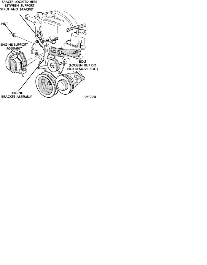
(14)Loosen but DO NOT REMOVE the bolt (Fig.
16)holding the engine bracket assembly to the engine support assembly.
(15)Remove upper alternator to alternator bracket mounting bolt (Fig. 17). Rotate the alternator assembly back toward the dash panel.
19 - 16 STEERING |
|
Ä |
|
Fig. 15 Power Steering Fluid Reservoir Mounting
Fig. 13 Serpentine Belt Tensioner
Fig. 16 Engine Bracket Support Assembly
Fig. 14 Bracket Support Strut
(16)Remove the 4 bolts holding the alternator bracket to the engine and intake manifold (Fig. 17). Remove alternator bracket from engine.
(17)Remove the alternator assembly, to lower alternator bracket bolt (Fig. 17). Without removing wiring harness from alternator. Remove alternator from bracket and lay alternator on top of intake manifold.
(18)Remove the power steering pump out through the top, in the area between engine and dash panel where the alternator was mounted.
Fig. 17 Alternator Mounting