

19 - 32 STEERING
Fig. 10 Steering Column Support Bracket
harness from the steering column assembly by prying out the plastic retainer buttons (Fig. 8).
(19)Remove the lower dash panel and support bracket standoff fasteners (Fig. 1).
(20)Remove the steering column assembly out through the passenger compartment. Use care to avoid damaging the paint or interior trim.
STEERING COLUMN INSTALLATION
(1)For column shift vehicles, install a new cable attaching grommet into the steering column shift lever (Fig. 11). Install grommet from the cable side of the lever. Use pliers and a back-up washer to snap the grommet into place (Fig. 11). Use Mopart Multipurpose Lubricant, or equivalent, to aid installation of the grommet. A replacement grommet should be used whenever the rod is disconnected from the lever.
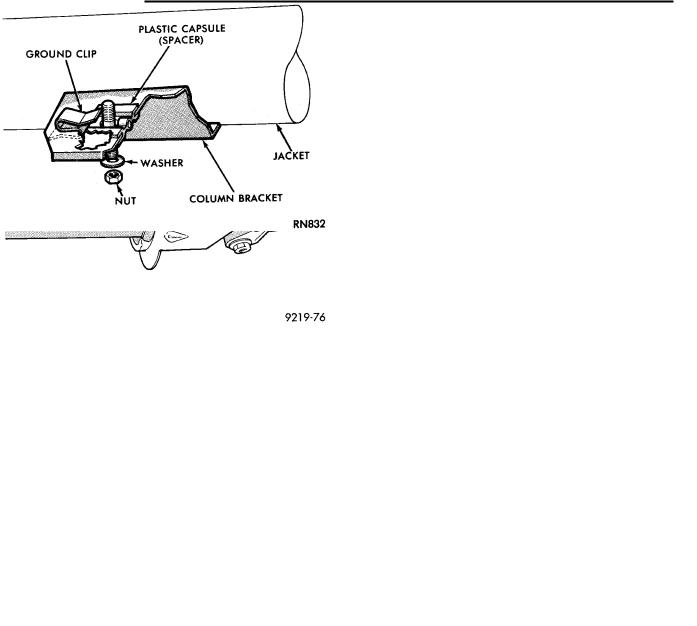
(2)Install the ground clip on the left capsule slot (Fig. 12). The plastic capsules should be preassembled in the bracket slots. Remove the shipping lock pin (Fig. 1) located on lower column jacket when installing a new steering column.
Insert the column through the floor pan opening while being careful to avoid damaging the interior paint and trim.
(3)Position the steering column assembly in the vehicle. Align the steering column assembly mounting bracket slots on the brake pedal bracket attaching studs (Fig. 13). Install, but loose assemble the two upper column bracket, washers and nuts.
(4)Make sure the front wheels are in the straightahead position. Align and assemble the upper steering coupler to lower steering coupler. Install the up-
per to lower steering coupler retaining bolt and nut. Torque the retaining bolt nut to 28 NIm (250 in. lbs.).
Ä
Fig. 11 Replacement Cable Grommet Installation
Fig. 12 Ground Clip & Spacer Installation
Be sure to install the upper to lower steering coupler retaining bolt retention pin (Fig. 6).
(5)Install the buttons which retain the multi function switch wiring harness to the steering column. Connect the multi-function switch wiring harness
connector to the multi-function switch. Torque the connector retaining bolt to 2 NIm (17 in. lbs) using a 7mm socket (Fig. 8).
(6)Install the upper fixed shroud onto the steering column assembly.
(7)Be sure both breakaway capsules are fully seated in the slots of the steering column upper sup-
port bracket. Torque the 2 upper steering column assembly to support bracket nuts to 12 NIm (105 in.
lbs.). Torque the 2 lower steering column assembly to mounting bracket nuts to 12 NIm (105 in. lbs.).