


19 - 34 STEERING
Fig. 1 Gear Shift Lever Removal
INSTALL
(1)Support the steering column assembly as shown in (Fig. 1) using a suitable size socket.
(2)Install the gear shift lever into the steering column assembly. Align the roll pin holes in the gear shift lever and the steering column assembly.
(3)Carefully Install the roll pin into the steering column assembly and through the shift lever. If the roll pin binds check the alignment on the holes. Be sure roll pin is fully installed into the steering column assembly.
IGNITION SWITCH SERVICE
TEST AND REPAIR
If the ignition switch effort seems to be excessive due to binding. Follow the procedure outlined below to determine the cause.
When service procedures are performed on the Acustar steering column there are certain areas of the column that can not be tampered with. If a problem related to these areas of the steering column are detected. The entire steering column (less the removable components) should be replaced see (Fig. 2 and 3).
(1)Remove the ignition switch from the steering column. Refer to Group 8H Electrical.
(2)Using a key cylinder, check the turning effort of the switch.
²If the ignition switch binds look for the following conditions.
Ä
Fig. 2 Steering Column Non-Serviceable
Components
(1)Look for for rough areas or flash in the casting and if found remove with a file (Fig. 3).
(2)Remove the link and slider.
Fig. 3 Steering Column Flash Removal And Non-
Serviceable Components
(3) Check the link to see if it has been bent and if so replace with a new part.
Put the slider in its slot in the sleeve and verify a loose fit over the length of the slot. If the slider binds in the slot at any point lightly file the slider until clearance is achieved.
² If no binding is found.
Lightly file the ramp on the ignition switch, (The ramp fits into the casting) until binding no longer occurs.

Ä |
|
STEERING 19 - 35 |
|
AUTOMATIC TRANSMISSION SHIFTER/IGNITION INTERLOCK
INDEX
|
page |
General Information . . . . . . . . . . . . . . . . . . . . . . |
. 35 |
Interlock System Adjustment . . . . . . . . . . . . . . . . |
. 35 |
GENERAL INFORMATION
The automatic transmission Shifter/Ignition Interlock, is a mechanically cable operated system (Fig. 1). It interconnects the automatic transmission floor mounted shifter to the steering column ignition switch. The interlock system locks the floor mounted shifter on automatic transmission equipped vehicles into the PARK position. The Interlock system is engaged whenever the ignition switch is in the LOCK or ACCESSORY position. When the key is in the OFF or RUN position the shifter is unlocked and will move into any position. The interlock system also prevents the ignition switch from being turned to the OFF or ACCESSORY position. Unless the shifter is fully locked into the PARK position.
INTERLOCK SYSTEM OPERATION CHECK
(1) With the shifter in PARK, and the shifter knob pushbutton in its full up position. The ignition
|
page |
Interlock System Operation Check . . . . . . . . . . . |
. 35 |
Shifter/Ignition Interlock Cable . . . . . . . . . . . . . . |
. 37 |
switch should rotate freely from its OFF/RUN to LOCK position. If the shifter is moved to the DRIVE (or OVERDRIVE) position if so equipped. The ignition switch should not rotate from its OFF/RUN to LOCK position.
(2)Moving the shifter out of PARK position, should only be possible when the ignition switch is in the OFF/RUN position. Movement of the shifter from the PARK position should not be possible, when the ignition switch is in the LOCK position.
(3)If the automatic transmission Shifter/Ignition Interlock System operates in any way other then as described above. Diagnosis, adjustment and or repair of the system is required. See Adjustment and Repair procedures in this section of the service manual.
INTERLOCK SYSTEM ADJUSTMENT
If the ignition switch is binding, effort is high or can not be turned to the OFF position, with the
Fig. 1 Shifter Ignition Interlock System Components
19 - 36 STEERING |
|
Ä |
|
shifter fully locked in the PARK position. Adjustment of the Interlock System may be required. To adjust the Interlock System follow the procedure listed below.
(1)Turn the ignition switch to the ACCESSORY position. The Interlock System will not adjust properly if the ignition switch is in the LOCK position.
(2)Remove the shift knob to shifter retaining screw and shift knob from shifter (Fig. 2). Leave the shifter release button in shifter handle.
Fig. 2 Removing Shift Knob And PRNDL Plate
(3)Remove the PRNDL plate (Fig. 2) from the center console. PRNDL plate is removed by gently prying between plate and console with a screw driver. Use care so not to damage plate or console assembly.
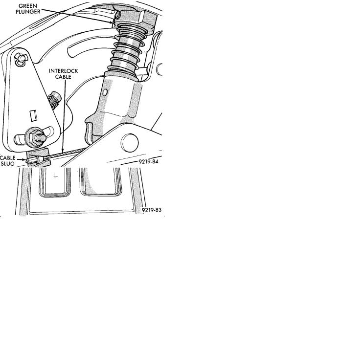
(4)Place the shifter in PARK, and ensure that the green plunger (Fig. 3) on the shifter mechanism is in the full up position.
(5)Check that the interlock cable slug is completely seated into the shifter interlock lever (Fig. 3).
(6)Check that the ignition switch is still in the accessory position (Fig. 1). Loosen the shifter interlock lever adjustment nut, (Fig. 4) enough to allow the spring to correctly position the interlock lever on the shifter assembly.
(7)Then torque the interlock lever adjustment nut to 2 NIm (15 in. lbs.) minimum 3 NIm (25 in. lbs.) maximum.
Fig. 3 Plunger Position For Interlock Adjustment
Fig. 4 Adjusting Interlock Lever
(8)Install the PRNDL plate (Fig. 2) back into the center console.
(9)Install the shift knob onto the shifter assembly.
Install the shift knob to shifter retaining screw and torque to 3 NIm (25 in.lbs.) (Fig. 2).
(10)After adjusting the interlock system, perform the interlock system operation check. See Interlock System Operation Check in this section of the service manual.

Ä
SHIFTER/IGNITION INTERLOCK CABLE
REMOVE
(1)Disconnect and isolate, the battery negative (-) cable from the vehicle battery.
(2)Remove the lower dash panel bolster and inside hood release lever, (Fig. 5) from the vehicle instrument panel.
Fig. 5 Remove Hood Release lever And Dash Panel Bolster
(3)Remove the tilt lever (Fig. 6) (if so equipped) from the steering column assembly.
(4)Remove the 3 screws mounting the upper steering column shrouds to the steering column assembly and remove shrouds (Fig. 6).
Fig. 6 Upper Steering Column Shroud And Tilt Lever
STEERING 19 - 37
(5) Remove the 2 nuts holding the upper steering column mounting bracket, to the steering column support bracket (Fig. 7). Lower steering column for clearance when removing lower shrouds from steering column.
Fig. 7 Steering Column Mounting Bracket
(6) Remove the 3 screws mounting the lower steering column shroud to the steering column assembly and remove shroud (Fig. 8).
Fig. 8 Lower Steering Column Shroud
(7)Remove shift knob to shifter retaining screw and remove knob from shifter assembly. Remove PRNDL plate from the console assembly (Fig. 9).
(8)Remove center console assembly. Refer to Group 23 Body, in this service manual for the appropriate procedure for the body style being serviced.
(9)Loosen but do not remove the interlock lever adjusting nut (Fig. 10) on the shifter assembly.
(10)Remove interlock cable from interlock lever on the shifter assembly (Fig. 10). Remove interlock

19 - 38 STEERING |
|
Ä |
|
Fig. 9 Shift Knob And PRNDL Plate Removal
Fig. 10 Interlock Adjusting Nut
cable from shifter assembly by grasping cable and pulling strait out from front of shifter assembly (Fig. 11).
(11) Remove the interlock cable routing clip from the throttle pedal bracket (Fig. 12). Removal of the
Fig. 11 Interlock Cable Removal
clip can be done by using needle nose pliers to compress barbs on clip and removing from holes in bracket.
Fig. 12 Remove Interlock Routing Clip
(12)Remove the 2 screws holding the interlock mechanism to the steering column (Fig. 13). Mechanism is held to column by clips on back of mechanism, then pull mechanism strait out from steering column.
(13)Route interlock cable from under center console mounting bracket and out front of dash panel.